Mechanical Engineering Exam  >  Mechanical Engineering Notes  >  Solid Mechanics  >  Bending & Shear Stress in Beams - 2

Bending & Shear Stress in Beams - 2 | Solid Mechanics - Mechanical Engineering PDF Download

Simple Bending Theory

When a beam having an arbitrary cross section is subjected to transverse loads the beam will bend. In addition to bending the other effects such as twisting and buckling may occur, and to investigate a problem that includes all the combined effects of bending, twisting and buckling could become a complicated one. Thus we are interested to investigate the bending effects alone, in order to do so, we have to put certain constraints on the geometry of the beam and the manner of loading.

1. Assumptions
The constraints put on the geometry would form the assumptions:

  • Beam is initially straight, and has a constant cross-section.
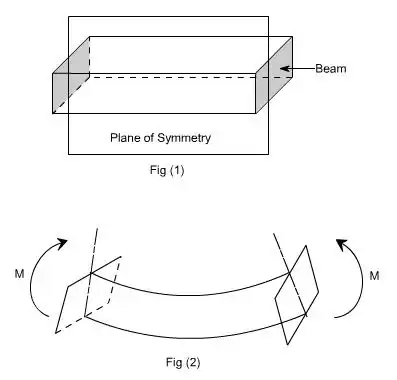
  • Beam is made of homogeneous material and the beam has a longitudinal plane of symmetry.
  • Resultant of the applied loads lies in the plane of symmetry.
  • The geometry of the overall member is such that not the bending,it is the buckling that is the primary cause of failure.
  • Elastic limit is nowhere exceeded and ‘E' is same in tension and compression.
  • Plane cross - sections remains plane before and after bending.
    Bending & Shear Stress in Beams - 2 | Solid Mechanics - Mechanical Engineering

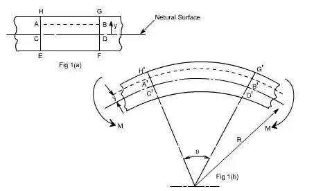
Let us consider a beam initially unstressed as shown in fig 1(a). Now the beam is subjected to a constant bending moment (i.e. ‘Zero Shearing Force') along its length as would be obtained by applying equal couples at each end. The beam will bend to the radius R as shown in Fig 1(b)
As a result of this bending, the top fibers of the beam will be subjected to tension and the bottom to compression it is reasonable to suppose, therefore, that some where between the two there are points at which the stress is zero. The locus of all such points is known as neutral axis. The radius of curvature R is then measured to this axis. For symmetrical sections the N. A. is the axis of symmetry but what ever the section N. A. will always pass through the centre of the area or centroid.
The above restrictions have been taken so as to eliminate the possibility of 'twisting' of the beam.

The concept of pure bending

  1. Loading restrictions
    As we are aware of the fact internal reactions developed on any cross-section of a beam may consists of a resultant normal force, a resultant shear force and a resultant couple. In order to ensure that the bending effects alone are investigated, we shall put a constraint on the loading such that the resultant normal and the resultant shear forces are zero on any cross-section perpendicular to the longitudinal axis of the member,
    That means F = 0,
    or M = constant.
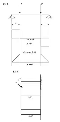
    Thus, the zero shear force means that the bending moment is constant or the bending is same at every cross-section of the beam. Such a situation may be visualized or envisaged when the beam or some portion of the beam, as been loaded only by pure couples at its ends. It must be recalled that the couples are assumed to be loaded in the plane of symmetry.
    Bending & Shear Stress in Beams - 2 | Solid Mechanics - Mechanical Engineering
    When a member is loaded in such a fashion it is said to be in pure bending. The examples of pure bending have been indicated in EX1 and EX2 as shown below:
    Bending & Shear Stress in Beams - 2 | Solid Mechanics - Mechanical Engineering
    When a beam is subjected to pure bending are loaded by the couples at the ends, certain cross-section gets deformed and we shall have to make out the conclusion that,
    (a) Plane sections originally perpendicular to longitudinal axis of the beam remain plane and perpendicular to the longitudinal axis even after bending, i.e. the cross-section A'E', B'F' (refer Fig 1(a)) do not get warped or curved.
    (b) In the deformed section, the planes of this cross-section have a common intersection i.e. any time originally parallel to the longitudinal axis of the beam becomes an arc of circle.
    Bending & Shear Stress in Beams - 2 | Solid Mechanics - Mechanical Engineering
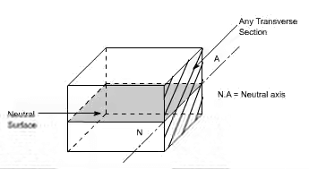
    We know that when a beam is under bending the fibres at the top will be lengthened while at the bottom will be shortened provided the bending moment M acts at the ends. In between these there are some fibres which remain unchanged in length that is they are not strained, that is they do not carry any stress. The plane containing such fibres is called neutral surface.
    The line of intersection between the neutral surface and the transverse exploratory section is called the neutral axis neutral axis (N A) .
  2. Bending Stresses in Beams
    M / I = E / R = σ / y
    This equation is known as the Bending Theory Equation.
    The above proof has involved the assumption of pure bending without any shear force being present. Therefore this termed as the pure bending equation. This equation gives distribution of stresses which are normal to cross-section i.e. in x-direction.
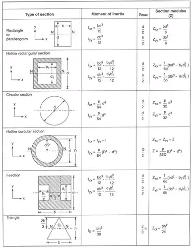
    Useful formulas for Ixx, Iyy, Zxx & Zyy
    Bending & Shear Stress in Beams - 2 | Solid Mechanics - Mechanical Engineering
The document Bending & Shear Stress in Beams - 2 | Solid Mechanics - Mechanical Engineering is a part of the Mechanical Engineering Course Solid Mechanics.
All you need of Mechanical Engineering at this link: Mechanical Engineering
33 videos|27 docs|29 tests

Top Courses for Mechanical Engineering

FAQs on Bending & Shear Stress in Beams - 2 - Solid Mechanics - Mechanical Engineering

1. What is bending stress in beams?
Ans. Bending stress in beams refers to the internal stress that occurs when a beam is subjected to bending moments. It can be described as the stress that develops within the beam due to the applied loads, causing the beam to bend.
2. What is shear stress in beams?
Ans. Shear stress in beams is the internal stress that occurs parallel to the cross-sectional area of the beam. It is caused by the shearing forces that act on the beam and can be defined as the force per unit area acting tangentially to the cross-section of the beam.
3. How is bending stress calculated in beams?
Ans. Bending stress in beams can be calculated using the formula σ = (M * c) / I, where σ is the bending stress, M is the bending moment, c is the distance from the neutral axis to the point of interest, and I is the moment of inertia of the beam's cross-section.
4. What factors affect the bending stress in beams?
Ans. Several factors can influence the bending stress in beams, including the magnitude and distribution of the applied loads, the shape and dimensions of the beam's cross-section, and the material properties of the beam. Additionally, the support conditions and the beam's length also play a role in determining the bending stress.
5. How does shear stress relate to bending stress in beams?
Ans. Shear stress and bending stress are both important factors in determining the overall stress distribution within a beam. While bending stress is responsible for the beam's resistance to bending moments, shear stress is responsible for the beam's resistance to shearing forces. In some cases, the combination of bending and shear stresses can lead to critical failure modes in beams.
33 videos|27 docs|29 tests
Download as PDF
Explore Courses for Mechanical Engineering exam

Top Courses for Mechanical Engineering

Signup for Free!
Signup to see your scores go up within 7 days! Learn & Practice with 1000+ FREE Notes, Videos & Tests.
10M+ students study on EduRev
Related Searches

shortcuts and tricks

,

Extra Questions

,

past year papers

,

Semester Notes

,

practice quizzes

,

pdf

,

Sample Paper

,

Exam

,

Previous Year Questions with Solutions

,

mock tests for examination

,

Bending & Shear Stress in Beams - 2 | Solid Mechanics - Mechanical Engineering

,

Free

,

ppt

,

Summary

,

Bending & Shear Stress in Beams - 2 | Solid Mechanics - Mechanical Engineering

,

Objective type Questions

,

Viva Questions

,

video lectures

,

Bending & Shear Stress in Beams - 2 | Solid Mechanics - Mechanical Engineering

,

Important questions

,

MCQs

,

study material

;