Metal Cutting


Introduction
"A manufacturing process in which a sharp cutting tool is used to discard material to leave the required part shape is known as machining."
In machining, shear deformation is the principal cutting action. As the tool advances, material ahead of the cutting edge undergoes intense shear along a plane called the shear plane, producing a chip and exposing a new surface.
Classification of the Material-Removal Process
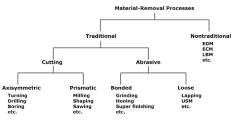
Cutting tools contain one or more sharp cutting edges and are made from materials harder than the work material. Cutting tools are classified into two major groups:
- Single-point cutting tools
- Multipoint cutting tools
- Multipoint cutting tools: Tools with more than one cutting edge to remove excess material. Example: milling cutters, drills, reamers, broaches, and grinding wheels.
- Single-point cutting tools: Tools having a single main cutting edge; the tool point has a rounded nose radius which affects surface finish and strength of the cutting edge. Single-point tools are used in operations such as turning, boring and shaping.
Geometry of a Right-Hand Single-Point Cutting Tool
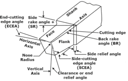 Right-hand single point cutting tool
The geometry of a single-point tool is described by several angles and linear dimensions that influence chip formation, cutting forces, tool wear and surface finish. Key nomenclature includes rake face, flank (clearance) face, cutting edge and nose radius.
 Single Point Cutting Tool
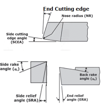
The important tool angles and their meaning:
- Back (or normal) rake angle (α): the angle between the rake face and a plane normal to the cutting surface; it controls chip flow and shear.
- Side rake angle: rake measured in the transverse plane; affects lateral chip flow.
- End relief angle and side relief angle: provide clearance between the flank and the machined surface to avoid rubbing.
- End cutting edge angle and side cutting edge angle: relate to the approach and cutting edge orientation relative to workpiece motion.
- Nose radius (R): a small rounded radius at the tool tip that affects surface finish and strength of the edge.
Tool Signature Systems
- ASA tool signature: expresses the geometry of the rake face in terms of back rake and side rake plus relief and cutting edge angles and nose radius.
- Normal or Orthogonal Rake System (ORS): a set of angles referenced to planes normal to the cutting edge. The normal rake angle (αn) is the maximum slope measured on a plane perpendicular to the side cutting edge. Tool signature in ORS is often written as:
I - αn - Side relief angle - End relief angle - End cutting edge angle - Approach angle λ - Nose radius R
where I is the angle of inclination, αn is normal rake, and the approach angle λ = 90° - side cutting edge angle.
Types of Metal Cutting Processes
Metal cutting may be classified according to the geometry of the cutting edge relative to the direction of cutting velocity.
- Orthogonal cutting (two-dimensional cutting): The cutting edge is oriented perpendicular to the cutting direction and the cutting action can be analysed in a plane. The chip is formed by shear along a single shear plane inclined at an angle φ (phi) to the surface.
- Oblique cutting (three-dimensional cutting): The cutting edge is inclined relative to the cutting direction so that the cutting action is three-dimensional. Most practical operations such as turning, milling and drilling are oblique cutting. Oblique cutting produces a helical or curled chip and requires consideration of components of forces and velocities in three dimensions.
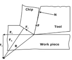 Various force acting in an orthogonal cutting
Forces in Metal Cutting
The principal forces acting in an orthogonal cutting operation are:
- Fc - Cutting force, acts in the direction of cutting velocity.
- Ft - Thrust or feed force, acts perpendicular to the cutting direction in the plane of the cross-section.
- Fs - Shear force acting on the shear plane.
- FN - Normal force to the shear plane.
- F - Frictional force along the rake face due to tool-chip interaction.
- N - Normal force on the tool rake face.
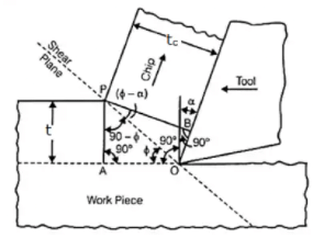
Merchant's Analysis for Chip Thickness Ratio
 Orthogonal cutting analysis
Definitions used in orthogonal cutting geometry:
- t - uncut chip thickness (feed per cutting pass).
- tc - chip thickness after cutting.
- r - chip thickness ratio, r = t / tc.
- φ - shear plane angle measured from the work surface to the shear plane.
- α - rake angle of the tool.
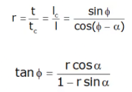
From geometry of orthogonal cutting the chip thickness ratio r is related to shear angle φ and rake α by:
r = t / tc = cos φ / sin(φ - α)
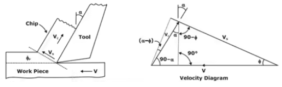
Velocity Triangle
 Velocity Triangle
Velocity relations in orthogonal cutting:
- V - cutting speed of the tool relative to the workpiece. For a rotating workpiece V = π D N / 60, where D is diameter (mm) and N is rpm.
- Vs - shear velocity along the shear plane.
- Vc - chip velocity measured along the chip flow.
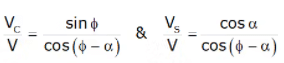
Chip conservation requires that the volumetric flux into the shear plane equals the flux carried away by the chip. Hence the chip velocity and thickness are related to the cutting speed by kinematic relations (for orthogonal cutting):
- The chip speed Vc and tool speed V are related by the chip thickness ratio: Vc = V · (t / tc) = V · r.
- The shear velocity Vs is related to V and geometry by the velocity triangle shown above.
Shear Strain
The shear strain γ on the shear plane in orthogonal cutting is given by:
γ = cot φ + tan(φ - α)
Merchant's Force Relations (Merchant's Circle)
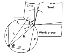 Merchant's Cutting Force circle
Force components on the shear plane and on the rake face are related by equilibrium:
- Fs = Fc cos φ - Ft sin φ
- FN = Ft cos φ + Fc sin φ (normal to shear plane)
- Friction and resultant tool forces are related by:
- F = Fc sin α + Ft cos α (frictional force along rake)
- N = Fc cos α - Ft sin α (normal on rake face)
Material Removal Rate and Specific Cutting Energy
Material removal rate (MRR) expresses the volume of material removed per unit time. For orthogonal and most turning/milling operations the formula is:
MRR = f · d · v
where
- MRR - material removal rate (mm3/s or mm3/min),
- f - feed (mm or mm/rev),
- d - depth of cut (mm),
- v - cutting speed (mm/s or m/s as appropriate).
Specific cutting energy (also called specific energy) is the energy required to remove a unit volume of material. It is obtained by dividing the power consumed by the MRR:
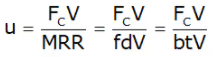
Typically, cutting power P = Fc · V, so the specific cutting energy U is:
U = (Fc · V) / MRR
The specific cutting energy depends on material, tool geometry, cutting conditions, strain hardening and friction at the tool-chip interface.
Relations for Shear Angle
Several analytical relations exist for predicting the shear angle φ as a function of cutting geometry and friction; the most commonly used are:
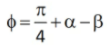
- Merchant's shear angle relation
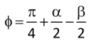
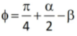
Merchant's relation is based on the minimum energy principle and introduces the friction angle β at the tool-chip interface. It yields an expression for φ in terms of α and β, commonly written as:
φ = 45° - α/2 + β/2
where β is the friction angle (tan β = F/N on the rake face).
- Lee and Shaffer relation
Lee and Shaffer derived an alternate relation by accounting for specific material behaviour under shear and strain hardening. Their expression links φ to cutting parameters and material constants.
- Stabler relation
Stabler proposed a relation that emphasises the effect of rake angle and chip compression; it is used for certain material/tool combinations where empirical calibration is available.
Types of Chips and Chip Formation
Chip formation depends on work material properties, tool geometry and cutting conditions. Broadly, chips are classified as:
- Discontinuous chips
- Continuous chips
- Continuous chips with Built-Up Edge (BUE)
- Continuous chips
Characteristics and promoting conditions:
- Formed when the work material is ductile and deforms plastically to form a continuous ribbon.
- Promoting conditions: sharp cutting edge, low feed and shallow depth of cut, large positive rake angle, high cutting speed, good lubrication/reduced tool-chip friction.
- Advantages: good surface finish, stable cutting forces. Disadvantages: chip control and evacuation must be managed (chip curlers, breakers).
- Discontinuous chips
Characteristics and promoting conditions:
- Formed when the material fractures during cutting producing segmented or broken chips.
- Promoting conditions: brittle materials (e.g., cast iron), low cutting speed, high tool-chip friction, large feed and depth of cut, small or negative rake angles.
- Advantages: easier chip control and disposal; disadvantages: poorer surface finish and higher cutting forces.
- Chips with Built-Up Edge (BUE)
Characteristics and promoting conditions:
- BUE forms when material adheres to and accumulates on the cutting edge, changing the effective tool geometry.
- Promoting conditions: low cutting speed, ductile material, high feed and depth of cut, low (small) positive rake angles, inadequate cutting fluid.
- Consequences: fluctuating cutting forces, degraded surface finish, and rapid tool wear once the BUE breaks away.
Taylor's Tool Life Equation
Tool life is the time a cutting tool can be used effectively before it must be replaced because of wear or failure. Taylor's empirical relation for tool life is:
V · Tn = C
where
- V - cutting speed,
- T - tool life (time or number of pieces),
- n - tool life exponent (depends on tool and work material combination),
- C - constant for a given tool-work material pair and specific failure criterion.
This equation is widely used to choose cutting speeds for desired tool life and to study the effect of tool materials and coatings.
Economics of Machining
Economics of machining is the selection and optimisation of process parameters to achieve required production rates and minimum cost.
Major cost components associated with machining are:
- Manpower cost C1 - operator wages per unit time (e.g., Rs per hour).
- Machine operating (overhead) cost Cm - includes machine depreciation, power consumption, maintenance, and consumables.
- Job handling cost - time and cost for loading/unloading, setup and handling while machine is idle for material transfer.
Two common economic optimisation criteria are:
(a) Minimum cost criterion
Choose cutting parameters (primarily cutting speed) to minimise total cost per part, balancing tool life, cycle time and overhead.
(b) Maximum production rate
Choose parameters to maximise production rate (minimise cycle time) subject to acceptable tool life and cost constraints. These analyses use Taylor's equation and cost per unit time to find optimal speeds.
Tool Wear
Tool wear mechanisms and their descriptions:
- Crater wear: A region worn on the rake face of the tool that is often roughly circular. It usually results from high temperature, chemical reactions and diffusion between the tool and chip; crater wear may not extend to the tool tip initially but weakens the tool and can change chip flow.
- Flank wear: Wear on the clearance (flank) face contacting the machined surface. The width of the wear land (commonly denoted VB) is used as a criterion for tool life and tool change. Flank wear results from abrasion, adhesion and mechanical rubbing.
Other wear/failure modes include chipping at the cutting edge, thermal cracking, plastic deformation of the edge, and notch wear at the depth-of-cut line. Diffusion and adhesion processes are important at high temperatures typical of high cutting speeds.
Tool life is commonly specified by a limiting flank wear width (e.g., VB = a specified value) or by a loss of dimensional tolerance/surface finish.
Machinability
Machinability describes how easily a material can be machined. It is influenced by material properties, microstructure, alloying elements, heat treatment and cutting conditions. Common indicators of machinability are:
- Tool life: For a given cutting speed and tool, a material that allows longer tool life is considered more machinable.
- Surface finish: Under identical cutting conditions, a material that produces a better surface finish is more machinable (important for finishing cuts).
- Cutting forces and power: Materials requiring lower cutting forces and power are easier to machine; this is important for small or older machines.
- Chip control: Ability to form short, broken chips that are easy to remove is desirable for automated machining.
- Heat and tool wear rates: Materials that cause less tool wear and lower cutting temperatures improve machinability.
Practical Notes, Examples and Applications
- Selection of tool geometry (positive vs negative rake, nose radius) involves trade-offs: positive rake reduces cutting forces and power but weakens tool edge; larger nose radius improves finish but increases cutting forces.
- Use of cutting fluids reduces tool-chip friction, cools the cutting zone, and improves surface finish and tool life; selection depends on material and operation.
- Chip breakers and curlers are used to control continuous chips for safety and automated handling; their design modifies chip flow and curvature.
- Hard and brittle materials (e.g., cast iron, ceramics) tend to produce discontinuous chips and may require special tooling (carbide, ceramics, CBN) and machining strategies.
- High volume production uses economic models with Taylor's equation to choose cutting speeds that balance tool cost and machine overhead for minimum unit cost or maximum throughput.
Summary
This chapter has covered the fundamental concepts of metal cutting: classification of cutting tools, single-point tool geometry, orthogonal and oblique cutting, chip formation and types, Merchant's analysis including chip thickness ratio and shear strain, velocity relations, forces and Merchant's circle, material removal rate and specific cutting energy, shear angle relations, tool life (Taylor's equation), economics of machining, tool wear mechanisms and machining performance (machinability). Understanding these core topics allows informed selection of cutting parameters, tooling and process strategies for efficient, economical and high-quality machining operations.
FAQs on Metal Cutting
| 1. What is metal cutting in mechanical engineering? |  |
| 2. What are the different methods of metal cutting? | |
| 3. What factors affect the cutting performance in metal cutting? | |
| 4. What are the advantages of metal cutting in mechanical engineering? | |
| 5. What safety precautions should be taken during metal cutting? | |


