Machining & Machine Tool Operations - 2 | Manufacturing Engineering - Mechanical Engineering PDF Download
Milling
- A machining operation in which a part of work is fed past a rotating tool of cylindrical shape with more than one cutting edge.
- An interrupted cutting operation; the teeth of the milling cutter enters and exits the work during each revolution. Due to this interrupted cutting action, the teeth are subjected to a cycle of impact force and thermal shock on every cycle. The tool material and cutter geometry have to be designed and manufactured to withstand these conditions.
Types of Milling Operations
Two basic types of milling operations are there,
- peripheral milling
- face milling

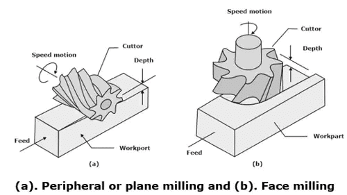
- Peripheral Milling
(i) The tool axis is parallel to the surface that has to be machined, and the operation is done by cutting edges on the external periphery of the cutter, hence this type of milling is called Peripheral or plain milling.
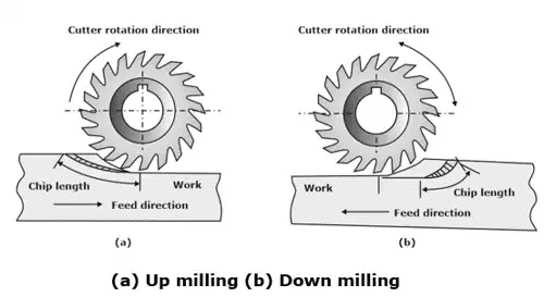
(ii) In this milling operation, on basis of the direction of cutter rotation, two forms of milling occurs: up milling and down milling. (a) Up Milling or Conventional Milling: In up milling (conventional milling) the direction of motion of the cutter teeth is opposite to that of the direction of feed, when the teeth cut into the work.
(b) Down Milling or Climb Milling: Down milling, that is milling against the feed, also called climb milling, the direction of cutter motion is the same as the direction of feed when the teeth cut the work. - Face milling: In this type of milling operation, the cutter axis is perpendicular to the surface that has to be milled, and machining operation is done by cutting edges on both the ends and outside periphery of the cutter.
Cutting Conditions in Milling
Determination of the cutting speed is done at the outside diameter of a milling cutter. Conversion of this cutting speed to spindle speed can be done by the use of the following formula:
N = V / πD
Generally, the feed in milling is given as a feed per cutter tooth; called the chip load,
fm = NZft
where fm = feed rate, mm/min (in/min)
N = spindle speed, rev/min
Z = number of teeth on the cutter
ft = chip load in mm/tooth (in/tooth)
material removal rate is:
MRR = w × d × fm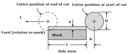 Slab (peripheral) milling showing entry of cutter into the workpiece

where A = approach distance for reaching the full depth of the cutter
d = depth of cut, mm
D = diameter of the milling cutter, mm.
The time Tm for which the cutter is engaged in milling the workpiece is given by = Tm = (L + A) / fm
Two possible cases arise for face milling :
- Firstly, feeding of the cutter is done from right to left across the workpiece. For the cutter to reach the full width of the work, it has to travel an approach distance given by

where D = cutter diameter, (mm)
w = width of the workpiece, (mm).
If D = w, then:
A = 0.5D
If D < w, then a slot of 0.5D is cut into the work.
- When the cutter is offset to one side of the work, the approach distance is given by

where w is the width of cut (in mm)
The machining time is given by the formula given below in any case:
Tm = (L + A) / f
In milling operation, there is a variation in the uncut chip thickness, it varies from minimum to maximum:
α = Rake angle
t1 = (t1)min to (t1)max
t1 min = 0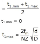
fm = Table speed or feed in mm/min
= N × f = N ×Z × ft
f = table feed in mm/rev
ft = table feed in mm/tooth
N = rpm of cutter
Z = Number of teeth
Average uncut chip thickness is given by:
Grinding
- Grinding is a chip-removal process that makes use of an individual abrasive grain as the cutting tool and it is achieved by abrasive particles that are present in the bonded grinding wheel rotating at very high surface speeds.
- The grinding wheels are generally disk-shaped and is precisely balanced for high rotational speeds.
The mean rake angle of the grains is negative to quite some extent, typically – 60° or even less. As a consequence that grinding chips undergo much larger plastic deformation than they do in any other machining process.
The Grinding Wheel
A grinding wheel has abrasive particles and bonding material. Five basic parameters of a grinding wheel are determined by the abrasive particles and bonding materials and the way the wheel is fabricated:
- abrasive material
- grain size
- bonding material
- wheel grade and
- wheel structure
For achieving the desired performance for a given application, each parameter must be carefully chosen.
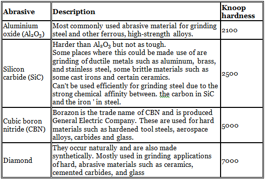
- Abrasive Material
Some of the properties of an abrasive material used in grinding wheels include high hardness, wear resistance, friability, toughness and friability.
Table: Abrasives of greatest importance in grinding
- Grain Size
(i) Better finish is produced by small grit sizes, larger grain sizes cause larger material removal rates.
(ii) Harder work materials need smaller grain sizes to cut efficiently.
(iii) Grain sizes in a grinding wheel usually range between 8 and 250. Grain size of 250 is very fine and the size of 8 is very coarse. - Bonding Materials
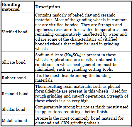
(i) Holding of the abrasive grains and establishment of the shape and structural integrity of the grinding wheel is taken care by the bonding material.
(ii) Some bonding materials commonly used in grinding wheels are :
- Wheel Structure & Wheel Grade
(i) The relative spacing of the abrasive grains in the wheel refers to the wheel structure.
(ii) In an open structure there are more pores and fewer grains per unit volume in the wheel.
(iii) To obtain better surface finish and dimensional control, dense structures are used.
Grinding Wheel Specification
The specification of the grinding wheel is as shown below :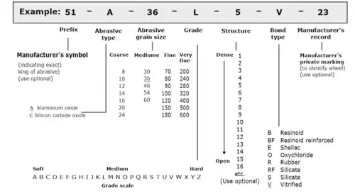
Grinding Ratio
- Grinding ratio (G) is defined as the

Centreless Grinding
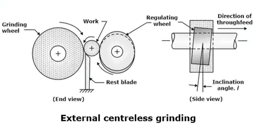
- External centreless Grinding
(i) For external centreless grinding, the set up consists of two wheels: the grinding wheel and a regulating wheel.
(ii) The work pieces, which may have many individual short pieces or long rods (i.e. 3–4 m long), get support from a rest blade and are fed through from between the two wheels.
The regulating wheel is inclined at a slight angle θ and rotates slowly to control through feed of the work.
(a) The following expression can be used to determine through feed rate, based on inclination angle and other parameters of the process:
fr = πDrNrSinθ
Where:
fr: through feed rate, mm/min
Dr: diameter of the regulating wheel, mm
Nr: rotational speed of the regulating wheel, rev/min
θ: inclination angle of the regulating wheel
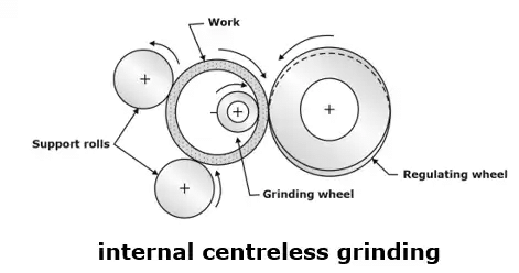
- Internal centreless Grinding
(i) The most common setup in internal centreless grinding consists rest blade, two support rolls which are used to maintain the position of the work.
(ii) The regulating wheel is inclined at a slight angle θ and rotates slowly to control through feed of the work. In order to support the grinding wheel, through feed of the work is not possible. Hence, this grinding operation cannot have the same high-production rates as that developed in the external centreless process.
Other Abrasive Processes
- Honing: Honing is an abrasive process done by a set of bonded abrasive sticks. Commonly used for finishing the bores of internal combustion engines.
- Lapping
(i) Lapping is an abrasive process used to generate surface finishes of very high accuracy and smoothness. Metal parts that are subjected to fatigue loading or surfaces that are used to establish a seal with a mating part are often lapped.
(ii) Parts requiring very good finishes such as optical lenses, metallic bearing surfaces etc make use of lapping process.
|
53 videos|53 docs|29 tests
|
FAQs on Machining & Machine Tool Operations - 2 - Manufacturing Engineering - Mechanical Engineering
| 1. What is machining in mechanical engineering? |  |
| 2. What are the different types of machine tools used in machining operations? |  |
| 3. What are the advantages of using machining in mechanical engineering? |  |
| 4. What are the common challenges faced in machining operations? |  |
| 5. How does computer numerical control (CNC) contribute to machining operations? |  |

|
Explore Courses for Mechanical Engineering exam
|

|
 (a) Up Milling or Conventional Milling: In up milling (conventional milling) the direction of motion of the cutter teeth is opposite to that of the direction of feed, when the teeth cut into the work.

