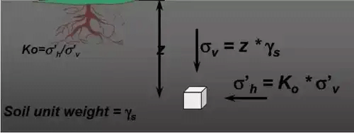
Vertical Stress in Ground


Stress Distribution in the Soil
At a point within a soil mass, stresses develop due to the weight of the soil above that point and due to any external loads applied to the ground surface or within the soil. Vertical stress increments in the ground are central to settlement and bearing capacity problems in geotechnical engineering.
Stress in the soil may be caused by:
- Self-weight of the soil (overburden pressure)
- Applied loads on the soil (loads from structures, live loads, point loads, strip loads, etc.)
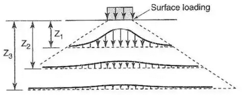
Finitely Loaded Areas
When the surface loading area is finite (for example point, circular, strip, rectangular or square loaded areas), the vertical stress increment in the subsoil decreases with increasing depth and with increasing horizontal distance from the loaded area. Several analytical and approximate methods exist to estimate the vertical stress increment beneath different shaped loaded areas.
Boussinesq's Theory (Point Load)
Purpose: The solution for a point (concentrated) load on the surface of a soil mass is a fundamental solution. It is used as the building block to obtain stresses under finite loaded areas by integration or superposition.
Assumptions made by Boussinesq
- The soil medium is an elastic, homogeneous, isotropic and semi-infinite medium extending infinitely in all directions from a horizontal free surface.
- The medium obeys Hooke's law (linear elasticity).
- The self-weight of the soil is ignored in the derivation of stress increments due to the applied load.
- The soil is initially unstressed before application of the point load.
- Change in volume of the soil on application of the load is neglected (infinitesimal strains).
- The top surface is free of shear stress except at the location of the applied point load.
- Continuity of stress is assumed throughout the medium.
- Stresses are distributed symmetrically about the vertical (z) axis through the point load.
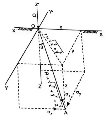
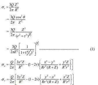
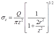
Boussinesq vertical stress expression:
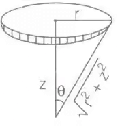
The vertical stress increment at a point located at depth z and radial distance r from the axis of a point load Q applied at the surface is
σz = (3Q / 2π) · (z³ / (r² + z²)^(5/2))
Define R = √(r² + z²). The expression may be written in terms of R as above. For convenience this is often written as
σz = KB · (Q / z²)
where KB is the Boussinesq influence factor that depends only on the ratio r / z:
KB = (3 / 2π) · (1 / (1 + (r / z)²)^(5/2))
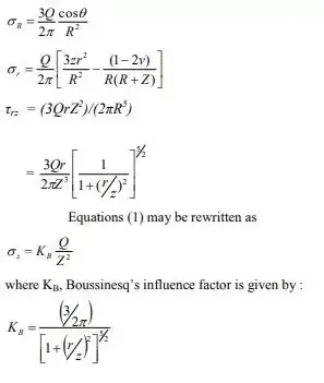
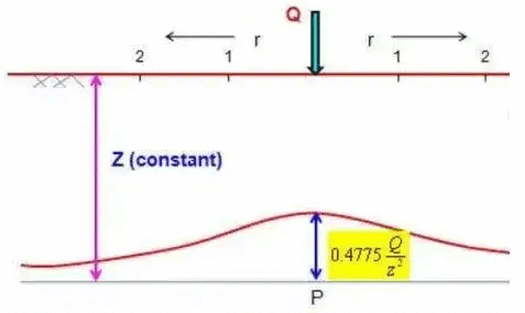
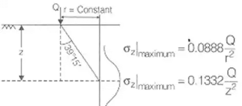
On axis (r = 0):
σz = (3Q) / (2π z²) ≈ 0.4775 · (Q / z²)
Remarks and useful values
- The factor KB decreases with increasing r/z; thus stress reduces with horizontal distance from the load.
- Table or charts of KB vs. r / z are commonly used for quick estimates. For r = 0, KB ≈ 0.4775.
- These Boussinesq solutions form the basis of influence charts and numerical integrations used for loads on finite areas.
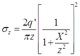
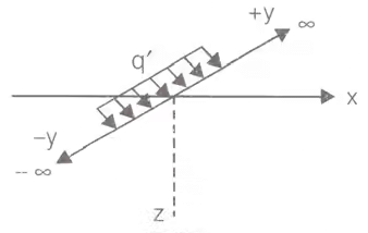
Westergaard's Theory
Physical basis: Westergaard proposed a solution that is appropriate for soils that behave as a system of vertical sheets or columns-this model reduces the lateral interaction of stress and is useful for layered or reinforced soils where the assumption of isotropy may be invalid.
Westergaard's vertical stress expression (point load):
σz = kw · (Q / z²)
where kw is a function of the ratio r / z under Westergaard's assumptions. On the axis (r = 0) the Westergaard factor is
kw|r=0 = 1 / π ≈ 0.3183
Westergaard results for some typical loads
- For distributed or strip loads Westergaard derived corresponding expressions for σz which differ from Boussinesq's because of the different stress interaction assumed.
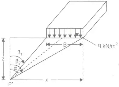
- For a strip or rectangular loaded area the formulas involve geometric parameters of the loaded area and the coordinate (x, z) of the point where stress is sought.
- For certain special cases these expressions reduce to simple forms; for example, directly beneath the centre of an infinitely long strip load the vertical stress for Westergaard's model can be expressed in terms of q' and z.
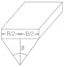
For a uniform circular loaded area, one convenient form of the expression is
σz = q · (1 - cos³θ)
where θ is the half-angle subtended at the point by the loaded area (cosθ determined by geometry of load and depth).

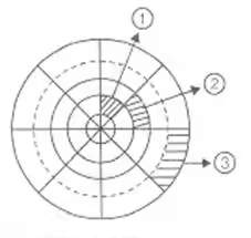
Newmark's Chart Method (Uniform Load on Irregular Areas)
Key idea: Newmark (1942) developed an influence chart based on the Boussinesq solution that permits calculation of the vertical stress increase at a point underneath an arbitrarily shaped uniformly loaded area by simple superposition.
- The method applies to a semi-infinite, homogeneous, isotropic and elastic soil mass; it is not applicable for layered soils without modification.
- Newmark's chart is most useful for uniformly distributed pressure over irregular plan shapes.
- The chart is divided into small sectorial areas (usually 200 sectors) formed by concentric circles and radial lines - commonly 10 concentric circles and 20 radial lines.
- Each sector has an influence value of 0.005 per unit pressure when the chart is constructed with 200 equal sectoral areas.
- To use the chart, the centre point for which vertical stress is required is placed at the centre of the chart and the loaded area is mapped onto the chart in plan. The number of sectors covered by the loaded area is counted and multiplied by the influence value and the applied pressure to give the vertical stress increase.
Influence of each sector = 1 / (total number of sectors) = 0.005 (for 200 sectors)
σz = 0.005 · q · NA where NA is the number of sectors covered by the projected loaded area on the chart.
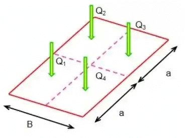
Approximate Methods for Vertical Stress beneath Finite Areas
When exact integration is inconvenient, approximate methods are used to estimate vertical stresses beneath finite loads. Common approximate methods include the Equivalent Load Method, Trapezoidal Method and Stress Isobar Method.
Equivalent Load Method
Replace the actual loaded area by a number of simpler elemental loads (point loads or circular areas), obtain vertical stress due to each element using an appropriate influence factor (for example Boussinesq or Westergaard), and superpose the results:
σz = σz1 + σz2 + σz3 + ...
where σzi = KBi · (Qi / z²) for Boussinesq-based elements, and Qi are the equivalent concentrated loads representing the actual distribution.
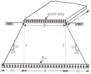
Trapezoidal Method
This method approximates the stress distribution by assuming an influence depth and linear variation in plan dimensions with depth (equivalent to sloping the loaded area sides at a specified slope η). For example, for a rectangular loaded area B × L with pressure q the approximate stress at depth z may be written as
σz = q · (B × L) / ((B + 2ηz)(L + 2ηz))
For the frequently used slope values the expressions simplify, e.g. for η = 1 (1H : 1V) the denominators become (B + 2z)(L + 2z) etc. The trapezoidal method provides a quick estimate but should be used with caution for deep or highly non-uniform loadings.
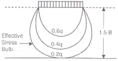
Stress Isobar Method
Contours (isobars) of equal vertical stress increment in plan are determined, and an area bounded by a selected isobar (for example the 0.2q isobar) is taken as the effective loaded area contributing to the stress at the depth of interest. The approximate rule uses the fact that stresses at depth are significantly influenced by a limited area around the vertical projection of the point.
0.2q indicates the 20% stress isobar used in some approximate procedures.
Worked Example
Q. A concentrated load of 22.5 KN acts on the surface of a homogeneous soil mass of large extent. Find the stress intensity at a depth of 15 metres and (i) directly under the load, and (ii) at a horizontal distance of 7.5 metres. Use Boussinesq's equations.
Ans:
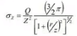
According to Boussinesq's theory the vertical stress at depth z and radial distance r is given by
σz = KB · (Q / z²)
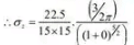
(i) Directly under the load (r = 0):
r = 0 ⇒ r / z = 0
Given: z = 15 m, Q = 22.5 kN = 22.5 × 10³ N
On-axis influence factor KB = 3 / (2π) ≈ 0.4775
Compute the vertical stress:
σz = 0.4775 · (Q / z²)
σz = 0.4775 · (22.5 × 10³ / 15²)
σz = 0.4775 · (22.5 × 10³ / 225)
σz = 0.4775 · 100 = 47.75 N/m²
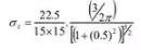
(ii) At a horizontal distance r = 7.5 m (z = 15 m):
r = 7.5 m, z = 15 m ⇒ r / z = 0.5
Compute the influence factor for r / z = 0.5 using the Boussinesq formula for KB:
KB = (3 / 2π) · (1 / (1 + (r / z)²)^(5/2))
KB = 0.4775 / (1 + 0.5²)^(5/2) = 0.4775 / (1.25)^(2.5)
KB ≈ 0.4775 / 1.7463 ≈ 0.2735
Now compute σz:
σz = 0.2735 · (22.5 × 10³ / 225)
σz = 0.2735 · 100 ≈ 27.35 N/m²
Result: (i) σz directly under the load at 15 m depth ≈ 47.75 N/m². (ii) σz at 15 m depth and 7.5 m horizontal distance ≈ 27.33-27.35 N/m².
Practical Notes and Applications
- Boussinesq and Westergaard solutions are fundamental for stress analysis in soils and are widely used to estimate stress increments that cause settlement beneath foundations, embankments and other structures.
- Newmark's influence chart is convenient for quick estimation of stress increases beneath irregularly shaped uniformly loaded areas.
- For layered soils, non-linear soils, or large strains, elastic theory results are only approximate and more sophisticated numerical methods (finite element, finite difference) or layered solutions should be used.
- Engineers must ensure consistent units and convert loads to N or kN and areas/lengths to metres when using the formulas above.
Key terms: vertical stress, stress increment, Boussinesq, Westergaard, Newmark chart, influence factor, semi-infinite elastic medium, equivalent load method, trapezoidal method, stress isobar.
FAQs on Vertical Stress in Ground
| 1. What is vertical stress in ground in civil engineering? |  |
| 2. How is vertical stress in ground calculated in civil engineering? | |
| 3. What are the factors influencing vertical stress in ground in civil engineering? | |
| 4. How does vertical stress in ground affect civil engineering projects? | |
| 5. How can vertical stress in ground be managed in civil engineering? | |


