A.C Bridges & Potentiometer | GATE Notes & Videos for Electrical Engineering - Electrical Engineering (EE) PDF Download
AC Bridges
AC bridges are used to measure self inductance, mutual inductance, capacitance and frequency.Types of Sources
- At low frequency, power line is used as source.
- At high frequency, electronic oscillator are used as source
- Vibration galvanometer at low power frequency and audio frequency (upto 1000 Hz)
- Head phones at audio frequency (250 Hz to 4 kHz)
- Tuneable amplifier for frequency range (10 Hz to 100 kHz)
General Bridge Circuit
At balanced bridge 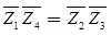
Magnitude condition | Z1 || Z4 | = | Z2 || Z3 |
Angle condition ∠θ1 + θ4 = ∠θ2 + ∠θ2
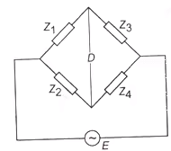 General bridge circuit
For balanced bridge both the magnitude
Measurement of Self Inductance
- Maxwell’s inductance bridge
- Maxwell’s inductance-capacitance bridge
- Hay’s bridge
- Anderson’s bridge
- Owne’s bridge
1. Maxwell’s Inductance Bridge
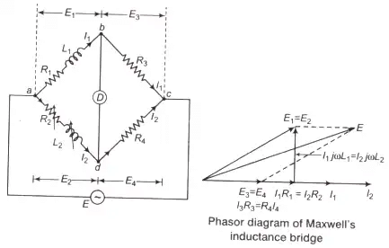
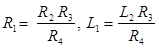
Where, L1 = Unknown inductance of resistance R1
L2 = Variable inductance
R2 = Standard variable resistance
R3, R4 = Fixed non-inductance resistance
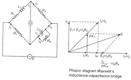
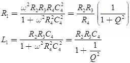
2. Maxwell’s Inductance - Capacitance Bridge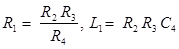
Q-factor,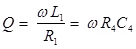
Q-factor range 1 < Q < 10, for medium Q-coils
Where, R4 = Variable non-inductive resistance
C4 = Standard variable capacitance
Note: If C4 is fixed, then balanced bridge obtained as
- Either by varying R2 and R4.
- Put a resistance in series with L1 and varying R4.
3. Hay’s Bridge
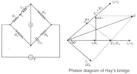
Where, C4 = Standar capacitance
Q-factor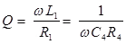
for Q > 10 i.e., high Q-coils
L1 = R2R3C4
4. Anderson’s Bridge
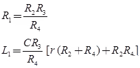
Where, L1 = Unknown self inductance with an internal resistance R1
R2, R3, R4 = Fixed standard non-inductive resistance
r = A variable resistance
C = A fixed capacitance
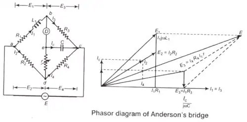
- Anderson’s bridge is suitable for small Q-factor i.e., Q < 1.
- It can also be used for measurement of capacitance in terms of inductance.
Key Points
- Maxwell's bridge is used to measure inductance of low Q-inductor.
- Hay bridge is used to measure inductance of a high Q-inductor.
- Inductance is measured in terms of a capacitance, resistance by Anderson’s bridge.
5. Owen’s Bridge
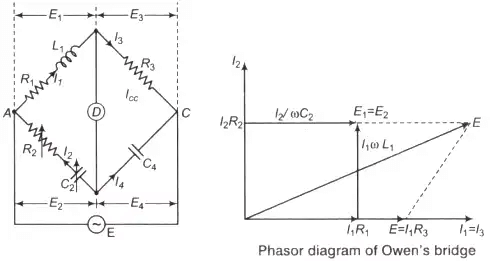
Where, L1 = Unknown self-inductance with internal resistance R1
R2 = Variable non-inductive resistance
R3 = Fixed standard non-inductive resistance
C2 = Standard variable capacitor
C4 = Fixed standard capacitor
Measurement of Capacitance
The capacitance can be measured with the help of following bridges
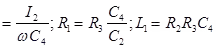
- De-Sauty Bridge

Where, C1 = Unknown capacitor
C2 = Standard capacitor
R3, R4 = Fixed non-inductive resistance
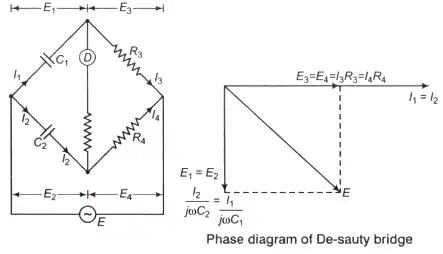
De-Sauty bridge can be used for the measurement of either air cored or gas filled capacitance only (loss less capacitor). - Schering Bridge
Dissipation factor D1 = tan δ = ωC1r1 = ωC4 R4
Where, C1 = Unknown capacitor with loss component r1
C2 = Fixed standard capacitor
R3 = Fixed standard non-inductive resistance
C4 = Variable capacitor
R4 = Variable non-inductive resistance

Key Points
- High voltage Schering bridge is used for determination of capacitance of insultaors, capacitor bushings and insulating oil and other insulating materials.
- Schering bridge is also used to measurement of relative permittivity of dielectric materials.
- The Schering bridge is one of the most widely used AC bridges.
- In order to measure low value of capacitance Schering bridge is used.
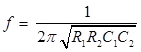
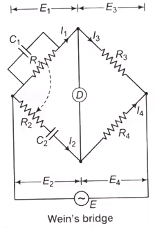
Measurement of Frequency
Frequency by Wein’s bridge.
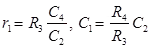
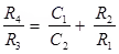
- Wein’s Bridge
Frequency,
For R1 = R2 = R
and C1 = C2 = C
and C1 = C2 = C- Wein’s bridge used as a natch Fitlter in harmonic distaration amalyzer.
- A frequency isolator in high frequency oscillator and amplifier circuit.
- A notch filter in a harmonics distortion analyser where it is used to isolate and elilminate the fundamental frequency component from the output of the amplifier under test.

Wagner’s Earthing Device
It is used to eliminate the effect of earth capacity-ance in measurement of capacitor using Schering bridge and it also used for high accuracy in measurement.
- Key Points
- Carey-foster bridge is specially designed to determine the difference between two nearly equal resistances.
- The potentiometer wire should have high specific resistance and low temperature coefficient.
- Sensitivity of a potentiometer can be increased by increasing the length of potentiometer wire.
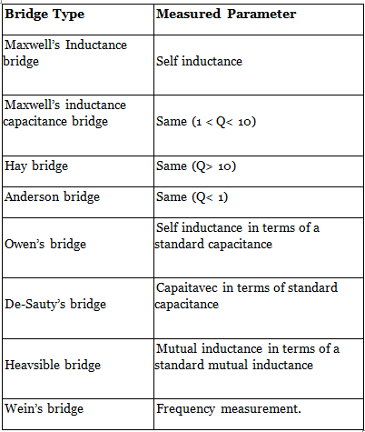
- Comparison between Different Types of Bridges
DC & AC Potentiometer
- DC Potentiometer
This is a very basic instrument used for comparing emf two cells and for calibrating ammeter, voltmeter and watt-meter. The basic working principle of potentiometer is very very simple. Suppose we have connected two battery in head to head and tale to tale through a galvanometer. That means the positive terminals of both battery are connected together and negative terminals are also connected together through a galvanometer.- Since a potentiometer measures voltage, it can also be used to detect current simply by measuring the voltage drop produced by the unknown current passing through a known standard resistance.
- The potentiometer is extensively used for a calibration of voltmeters and ammeters and has in fact become the standard for the calibration of these instruments. For the above mentioned advantages the potentiometer has become very important in the field of electrical measurements and calibration.
Standardization: Since the resistance of slide wire is known accurately, the voltage drop along the slide wire can be controlled by adjusting the value of working current. The process of adjusting the working current so as to match the voltage drop across a portion of sliding wire against a standard reference source is known as "Standardization".Here in the figure it is clear that if the voltage of both battery cells is exactly equal, there will be no circulating current in the circuit and hence the galvanometer shows null deflection. The working principle of potentiometer depends upon this phenomenon.Now by adjusting sliding contact on the resistor, it is found that the null deflection of galvanometer comes for first cell at a length of L on the scale and after positioning to way switch to second cell and then by adjusting the sliding contact, it is found that the null deflection of galvanometer comes for that cell at a length of L1 on the scale.Let's think of the first cell as standard cell and it's emf is E and second cell is unknown cell whose emf is E1. Now as per above explanation,
E = Lv volt and
E1 = L1v volt
Dividing one equation by other, we get
E/E1 = L/L1
As the emf of the standard cell is known, hence emf of the unknown cell can easily be determined.
- A.C Potentiometer
The Potentiometer is an instrument which measures unknown voltage by balancing it with a known voltage. The known source may be DC or AC. The working phenomenon of DC potentiometer and AC potentiometer is same. But there is one major difference between their measurements, DC potentiometer only measures the magnitude of the unknown voltage. Where as, AC potentiometer measures both the magnitude and phase of unknown voltage by comparing it with known reference.
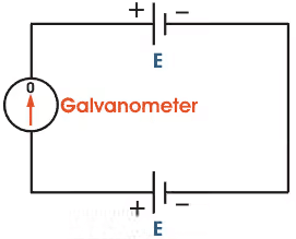 Here in the figure it is clear that if the voltage of both battery cells is exactly equal, there will be no circulating current in the circuit and hence the galvanometer shows null deflection. The working principle of potentiometer depends upon this phenomenon.
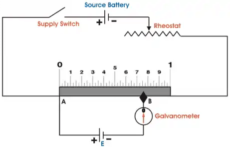 Now by adjusting sliding contact on the resistor, it is found that the null deflection of galvanometer comes for first cell at a length of L on the scale and after positioning to way switch to second cell and then by adjusting the sliding contact, it is found that the null deflection of galvanometer comes for that cell at a length of L1 on the scale.Let's think of the first cell as standard cell and it's emf is E and second cell is unknown cell whose emf is E1. Now as per above explanation,
There are two types of AC potentiometers:
- Polar type potentiometer.
- Coordinate type potentiometer.
1. Polar type Potentiometer
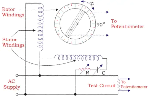
In such type of instruments, two separate scales are used to measure magnitude and phase angle on some reference of the unknown e.m.f. There is a provision on the scale that it could read phase angle up to 3600. It has electrodynamometer type ammeter along with DC potentiometer and phase-shifting transformer which is operated by single phase supply.
- In phase-shifting transformer, there is a combination of two ring-shaped laminated steel stators connected perpendicularly to each other, One is directly connected to power supply and the other one is connected in series with variable resistance and capacitor.
- The function of the series components is to maintain constant AC supply in the potentiometer by doing small adjustments in it. Between the stators, there is laminated rotor having slots and winding which supplies voltage to the slide-wire circuit of the potentiometer.
- When current start flowing from stators, the rotating field is developed around the rotor and due to it e.m.f. is induced in the rotor winding.The induced emf in rotor winding by stator winding 1 can be expressed as
E1 = KI sinwt.cosΦ
The induced emf in the rotor winding by the stator winding 2
E1 = KI (sinwt + 90o).(cosΦ + 90o)
From the above equation, we get
E = KI (sinwt cos∅ - coswt sin∅)
Therefore, resultant induced emf in the rotor winding due to two stator winding
E = kI sin(wt - ∅)
Where, Ø gives the phase angle.
 The induced emf in rotor winding by stator winding 1 can be expressed as
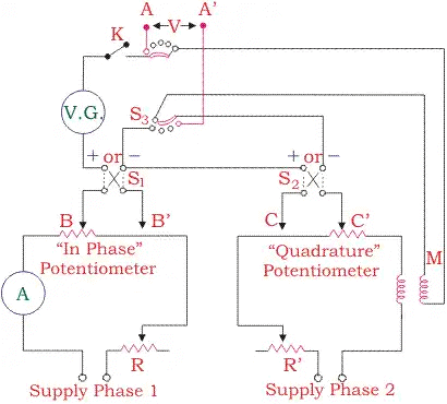
- In coordinate AC potentiometer, two separate potentiometers are caged in one circuit.
- The first one is named as the in-phase potentiometer which is used to measure the in-phase factor of an unknown e.m.f. and the other one is named as quadrature potentiometer which measures quadrature part of the unknown e.m.f. the sliding contact AA’ in the in-phase potentiometer and BB’ in quadrature potentiometer are used for obtaining the desired current in the circuit.
- By adjusting rheostat R and R’ and sliding contacts, the current in the quadrature potentiometer becomes equal to the current in the in-phase potentiometer and a variable galvanometer shows the null value.
- S1 and S2 are signs changing switches which are used to change the polarity of the test voltage if it is required for balancing the potentiometer.
- There are two step-down transformers T1 and T2 which isolate potentiometer from the line and give an earthed screens protection between the winding.
- It also supplies 6 volts to potentiometers.
Thus, the resultant voltage of the coordinate AC potentiometer is
And the phase angle is given by
Applications of AC Potentiometer
- Measurement of self-inductance.
- Calibration of voltmeter.
- Calibration of Ammeter.
- Calibration of wattmeter.
|
27 videos|328 docs
|
FAQs on A.C Bridges & Potentiometer - GATE Notes & Videos for Electrical Engineering - Electrical Engineering (EE)
| 1. What is an AC bridge? |  |
| 2. How does an AC bridge work? | |
| 3. What is the difference between AC and DC potentiometer? | |
| 4. How does a potentiometer work? | |
| 5. What are the advantages of using AC bridges and potentiometers? | |

|
4.85/5 Rating |

|
Jan 03, 2025 Last updated |
|
27 videos|328 docs
|

|
Explore Courses for Electrical Engineering (EE) exam
|
|
mock tests for examination
,MCQs
,ppt
,Important questions
,past year papers
,Free
,Extra Questions
,practice quizzes
,shortcuts and tricks
,Objective type Questions
,Semester Notes
,Sample Paper
,Summary
,study material
,Previous Year Questions with Solutions
,A.C Bridges & Potentiometer | GATE Notes & Videos for Electrical Engineering - Electrical Engineering (EE)
,Exam
,video lectures
,A.C Bridges & Potentiometer | GATE Notes & Videos for Electrical Engineering - Electrical Engineering (EE)
,Viva Questions
,A.C Bridges & Potentiometer | GATE Notes & Videos for Electrical Engineering - Electrical Engineering (EE)
;


A.C Bridges & Potentiometer Free PDF Download
Importance of A.C Bridges & Potentiometer
A.C Bridges & Potentiometer Notes
A.C Bridges & Potentiometer Electrical Engineering (EE) Questions
Study A.C Bridges & Potentiometer on the App
|
© EduRev
|
Education Revolution
|


|


