Light Propagation in Optical Fibers

Fibre Optic Communications
Fibre optic communication is a method of transmitting information from one place to another by sending pulses of light through an optical fibre. The information-carrying capacity of a channel is directly proportional to its available bandwidth. Light is an electromagnetic wave and can be used as a carrier for information signals; because light has a very high frequency compared with typical information signals, very large bandwidths are easily available.
A typical fibre-optic communication link comprises the following functional elements:
- Transducer - converts information from the source into an electrical signal.
- Optical source - a semiconductor LED or a semiconductor laser (for example, an injection laser diode) converts the electrical signal into an optical (light) signal.
- Optical channel - the optical fibre that guides the light.
- Optical detector - converts the received optical signal back to an electrical signal; common detectors are PIN photodiodes and Avalanche Photodiodes (APD).
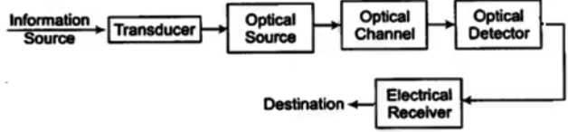 Block diagram of fibre optic communication
Basic Optics and Light Propagation
When light encounters matter, different models are used depending on the problem: the photon (quantum) picture for material-photon interactions, the wave picture for transmission and interference, and the ray picture for comparing paths in different media. For ray-based analysis of fibres, the following optical laws apply.
- Reflection - the angle of incidence equals the angle of reflection.
- Refraction - when light passes from one medium to another, its direction changes. Snell's law describes refraction: n1 sin φ1 = n2 sin φ2, where n is the refractive index of the medium.
- Refractive index n = c / v, where c is the speed of light in vacuum and v is the speed in the medium. Typical values: n ≈ 1.0 in air, n ≈ 1.33 in water, n ≈ 1.5 in many glasses.
Total Internal Reflection
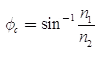
When light travels in a medium with refractive index n1 toward a boundary with a less dense medium of refractive index n2 (n1 > n2), there exists a critical angle θc beyond which all the light is totally internally reflected back into the denser medium. For refraction angle φ2 = 90°, Snell's law gives the critical angle:
n1 sin θc = n2
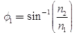
Total internal reflection occurs when the incident angle φ1 ≥ θc.
All guided information in an optical fibre is carried in the core by the principle of total internal reflection; the cladding provides a lower refractive index to enable this guiding. The cladding itself does not carry signal energy as guided modes.
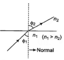 Total internal reflection in two mediums
- The critical angle is the angle of incidence that causes the refracted ray to travel along the boundary between two media.
- Most light that is guided along the fibre core does so by repeated total internal reflection at the core-cladding interface.
Fibre Construction and Materials
- Plastic Clad Silica (PCS) - a common cable type with a glass (silica) core and plastic cladding.
- The cladding protects the core and provides a controlled refractive-index boundary for guiding light.
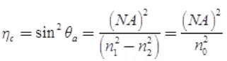
Acceptance Angle and Numerical Aperture (NA)
The acceptance angle θa is the maximum angle to the fibre axis at which a ray entering the fibre from the external medium (refractive index n0) will be guided by total internal reflection within the core.
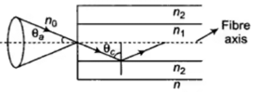 Acceptance angle of fibre
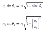
Using geometry and Snell's law at the entrance and at the core-cladding interface:
n0 sin θa = n1 sin(90° - θc) = n1 cos θc
The numerical aperture NA expresses the light-collecting ability of the fibre and relates the acceptance angle to the refractive indices involved:
NA = n0 sin θa = √(n12 - n22)
Relative Refractive Index Difference (Δ)
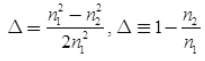
The relative refractive index difference Δ characterises the difference between core and cladding indices. For small Δ, NA can be approximated as:
NA = n1 √(2Δ)
Ray Types: Meridional and Skew Rays
Meridional rays are rays that cross the fibre axis; their acceptance condition is given by the standard NA formula.
Skew rays do not cross the axis; their effective acceptance angle θas is different and given by
NA = n0 sin θas cos γ = √(n12 - n22)
where γ is the angle between the ray direction and the normal at the entrance point. θas is always greater than θa, so more skew rays may be admitted for the same NA.
Normalized Frequency (V)
The normalized frequency (also called the V-number) determines the number of guided modes supported by a fibre. It is dimensionless and defined as:
V = (2π a / λ) × NA = (2π a / λ) × n1 √(2Δ)
where a is the core radius and λ is the operating wavelength in vacuum.
Step-Index Fibre
Step-index fibres have an abrupt change in refractive index between core and cladding:
n(r) = n1 for r < a
n(r) = n2 for r ≥ a
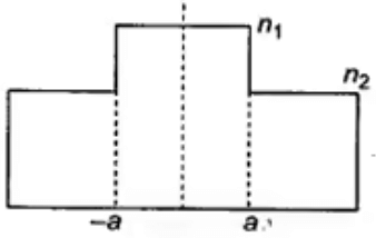 Step index fibre
Modes and Mode Volume
Mode refers to an allowed field distribution that propagates along the fibre. For a multimode step-index fibre the approximate number of guided modes (mode volume) M is
M ≈ V2 / 2
 Equal energy and equal phase
  Same phase but unequal energy
 Different phase but same energy
 - Single-mode fibre has a very small core diameter so that only the fundamental mode is supported.
- Multimode fibre has a larger core and supports many modes, which travel along different paths and arrive at different times.
- Different modal path lengths cause modal dispersion that stretches a light pulse and limits the bandwidth and pulse repetition rate. Single-mode fibre eliminates intermodal dispersion.
Graded-Index Fibre
Graded-index fibres have a core refractive index that decreases gradually from the centre towards the cladding; the highest index is at the centre and the lowest at the edge of the core. This refractive-index profile reduces modal dispersion by causing rays taking longer geometric paths to travel faster in lower-index regions, helping them to re-synchronise.
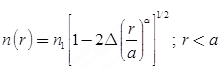
At the core edge (r ≥ a) the cladding index is given (for a step profile) by:
n2 = n1 [1 - 2Δ]1/2
The profile exponent α describes how sharply the index falls with radius; as α increases, a graded-index fibre tends towards step-index behaviour.
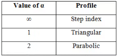
- As core radius a increases, graded-index behaviour approaches step-index behaviour.
- Graded-index fibres control multiple light-path delays so that modal dispersion is reduced compared with step-index multimode fibres.
- Modal dispersion is absent in single-mode fibres.
- The three widely used fibre types are: multimode step-index, single-mode step-index, and multimode graded-index.
The number of modes (mode volume) for a multimode fibre can be illustrated; see image below.
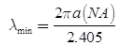
For single-mode operation the normalized frequency must lie in the range 0 ≤ V ≤ Vc, where Vc ≈ 2.405 (the first zero of the Bessel function). The minimum wavelength λ for single-mode transmission for a given core radius a can be obtained from the single-mode condition:
Losses in Optical Fibre
The primary performance specification for a fibre is its attenuation (loss), usually expressed in decibels per kilometre (dB/km). Light loss arises from absorption, scattering and various forms of dispersion.
Absorption losses are of two types:
- Intrinsic - due to the fundamental material absorption of the glass itself.
- Extrinsic - due to impurities such as OH- ions or transition-metal contaminants.
- Cable attenuation is proportional to its length.
- Typical losses range from about 1 dB/km (glass single-mode step-index) to as high as 100 dB/km (plastic multimode step-index) depending on materials and construction.
- Fibre-optic cables can be spliced and joined using adhesives or fusion splicing; the chosen method affects the splice loss.
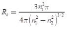
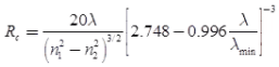
Critical Radius of Curvature
Bending a fibre too sharply causes radiation loss. The critical radius of curvature depends on the fibre type and wavelength.
Optical Sources
Fibre-optic systems commonly use two types of semiconductor light sources:
- Light Emitting Diodes (LEDs) - produce incoherent, relatively broad-spectrum light and are used in short-distance, low-speed systems.
- Injection Laser Diodes (ILDs) / Semiconductor lasers - produce coherent, narrow-spectrum light and are used in long-distance, high-speed systems.
- Most LEDs and ILDs used in communications emit in the near-infrared range (approximately 0.82 μm to 1.55 μm).
- In certain contexts (for example comparing gas lasers), for the same output optical power the required input power can differ between laser types (for instance, He-Ne versus ruby), but semiconductor lasers are preferred for fibre systems due to size, efficiency and emission wavelength.
Carrier Physics in LEDs and Lasers
In an LED the total recombination rate Rt equals the sum of radiative and non-radiative recombination rates:
Rt = Rr + Rnr
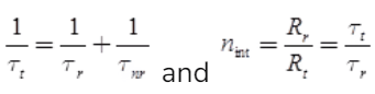
The internal quantum efficiency ηint is the fraction of recombinations that produce photons:
ηint = Rr / Rt
If the injected current is i and e is the electron charge, the total carrier injection rate equals i / e, so Rt ≈ i / e.

The internal optical power produced (photon energy hf per photon) is:
Pint = Rr × h f
Equivalently, using ηint and the electrical injection rate:
Pint = ηint × (i / e) × (h c / λ)
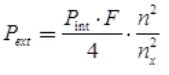
Here, F denotes the transmission coefficient for light leaving the active region (0 < F < 1). The external optical power Pext is smaller than Pint because of internal reflections and limited escape cone determined by refractive indices.
- External quantum efficiency is the ratio of external emitted photons to injected electrons; it is often expressed as optical power out divided by input electrical power.
- The carrier lifetimes are related by 1/τt = 1/τr + 1/τnr, where τr is the radiative lifetime and τnr the non-radiative lifetime.
Coupling Efficiency
Coupling efficiency is the fraction of optical power emitted by the source that is captured and guided by the fibre. It depends on source radiation pattern, NA of the fibre, and alignment/geometry of the source-fibre interface.
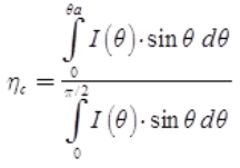
For a source with angular intensity I(θ) = I0 cos θ, the fraction of power within the acceptance cone can be computed by integrating the angular distribution over the acceptance solid angle.
Optical Detectors
The most commonly used photodetectors in fibre systems are PIN photodiodes and Avalanche Photodiodes (APD). PIN diodes are fast and sensitive; APDs offer internal gain (avalanche multiplication) providing higher sensitivity for long-distance links but require higher bias and careful noise management.
Desirable detector characteristics include high quantum efficiency, high responsivity, short response time, low noise and stability over the operating conditions.
Detector Quantum Efficiency and Responsivity
The quantum efficiency ηD of a detector is the ratio of the generated electron rate re to the incident photon rate rp:
ηD = re / rp
The incident optical power P0 is related to the photon rate by:
P0 = rp × h f
The responsivity R gives the electrical current produced per unit incident optical power and is related to quantum efficiency by:
R = (ηD × e) / (h f)
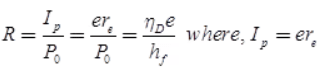
Thus the detector current Ip = R × P0, with P0 the incident optical power.
Summary
This chapter has covered the fundamentals of light propagation in optical fibres: basic optical laws, total internal reflection, acceptance angle and numerical aperture, ray types, normalized frequency and modes, step-index and graded-index fibres, modal dispersion and losses, critical bending radius, optical sources (LEDs and laser diodes), and detectors (PIN and APD). The provided formulas and parameters such as NA, V-number and mode-count determine guiding behaviour and bandwidth; source and detector efficiencies and coupling determine practical link power budgets.
FAQs on Light Propagation in Optical Fibers
| 1. What is light propagation in optical fibers? |  |
| 2. How does light propagate in optical fibers? | |
| 3. What are the advantages of using optical fibers for communication? | |
| 4. What are the different types of optical fibers? | |
| 5. What are the main challenges in light propagation through optical fibers? | |


 | Explore Courses for Electronics and Communication Engineering (ECE) exam |
 | Get EduRev Notes directly in your Google search |