Heat Transfer Through Fins


Heat Transfer from Extended Surface (Fin)
A fin (or extended surface) is a projection from a primary surface whose purpose is to increase the rate of heat transfer by increasing the surface area available for convection to the surrounding fluid. Fins are commonly used where direct increase of the convective coefficient is not feasible; adding surface area is often an economical and effective alternative.
- Finned surfaces are widely used in heat exchangers, radiators, electronic cooling, engine cooling fins and similar applications.
- In most analytical treatments the fin is assumed to operate at steady state and contain no internal heat generation.
- The convection heat transfer coefficient h is commonly taken as uniform over the fin surface for analysis simplicity.
- The basic convective heat transfer relation is Q = h A ΔT; since h and ΔT are often imposed by the situation, increasing the surface area A by fitting fins increases the rate of heat transfer.
Generalised Differential Equation for a Straight Fin (Rectangular Cross-section)
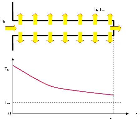
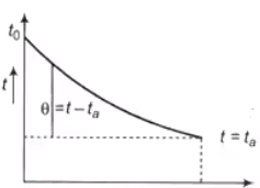
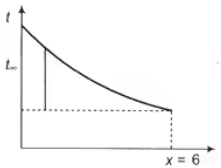
Consider a straight fin of uniform cross section attached to a large wall at x = 0 and extending to x = L. Define the temperature difference
θ(x) = T(x) - T∞, where T∞ is the ambient fluid temperature.
Let the fin have constant cross-sectional area Ac, thermal conductivity k, and wetted perimeter P (perimeter in contact with fluid). Heat loss from the fin surface per unit length is h P θ(x). A small element of length dx between x and x + dx gives an energy balance:
- Heat conducted into the element at x plus heat generated in element (zero here) minus heat conducted out at x + dx minus heat lost by convection from the element surface equals zero.
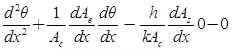
Writing the balance and simplifying gives the standard second-order ordinary differential equation:
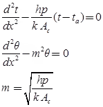
d²θ/dx² - (h P)/(k Ac) · θ = 0.
Define
m² = (h P)/(k Ac),
so the governing equation becomes
d²θ/dx² - m² θ = 0.
The general solution of this equation is
θ(x) = C₁ e^{m x} + C₂ e^{-m x},
where C₁ and C₂ are constants determined from boundary conditions at the base and the fin tip.
Definitions of symbols used
- θ(x) = excess temperature at distance x from base = T(x) - T∞.
- k = thermal conductivity of fin material.
- h = convection heat transfer coefficient (assumed uniform).
- Ac = cross-sectional area of the fin (constant for prismatic fin).
- P = wetted perimeter (total perimeter in contact with the fluid).
- m = sqrt(h P / (k Ac)).
Common Boundary Conditions and Three Standard Cases
Three practical boundary conditions at the tip lead to three commonly used analytical solutions:
- Case 1 - the fin is effectively infinitely long (L → ∞), so the tip temperature approaches the ambient: θ(L → ∞) = 0.
- Case 2 - the fin tip is insulated (negligible heat loss from the tip): dθ/dx at x = L = 0.
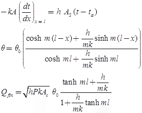
- Case 3 - the fin tip loses heat by convection to the fluid with the same h as on the lateral surface: -k Ac dθ/dx|ₓ=L = h At θ(L) (At is the tip area; for thin prismatic fins At ≈ Ac).
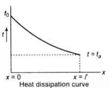
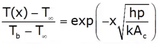
Case 1: Infinitely Long Fin (L → ∞)
Boundary conditions:
- At x = 0, θ = θ₀ = T₀ - T∞ (base temperature excess).
- As x → ∞, θ → 0.
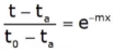
Applying the boundary conditions selects the decaying exponential solution:
θ(x) = θ₀ e-m x.
Heat conducted from the base (rate of heat transfer from fin to fluid) is found from Fourier's law at x = 0:
q = -k Ac (dT/dx)|ₓ=0 = -k Ac (dθ/dx)|ₓ=0.
Differentiate θ(x):
dθ/dx = -m θ₀ e-mx.
At x = 0 this gives
q = k Ac m θ₀.
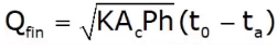
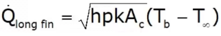
Using m = sqrt(h P /(k Ac)) this can be rearranged to the alternative form
q = √(h P k Ac) · θ₀.
Case 2: Fin with Insulated Tip (dθ/dx = 0 at x = L)
Boundary conditions:
- At x = 0, θ = θ₀.
- At x = L, dθ/dx = 0 (insulated tip).
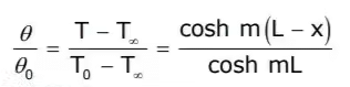
Applying the boundary conditions yields the temperature distribution
θ(x) = θ₀ · cosh[m (L - x)] / cosh(m L).
The heat rate at the base is
q = -k Ac (dθ/dx)|ₓ=0 = k Ac m θ₀ · tanh(m L).
Using m we may also write
q = √(h P k Ac) · θ₀ · tanh(m L).
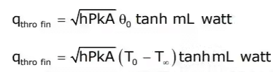
Case 3: Fin with Convective Tip
Boundary conditions:
- At x = 0, θ = θ₀.
- At x = L, -k Ac (dθ/dx) = h At θ(L), representing convection from the tip area At.
Solving with these boundary conditions gives a temperature distribution and a base heat flow q that include the effect of tip convection. The general expression for the heat flow from the fin base is
q = k Ac m θ₀ · [sinh(m L) + (h/(m k)) cosh(m L)] / [cosh(m L) + (h/(m k)) sinh(m L)].
This expression reduces to the insulated tip result when h/(m k) → 0, and to the infinite fin result when m L → ∞.
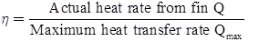
Fin Efficiency
The fin efficiency is a measure of how effectively the fin surface transfers heat relative to an ideal surface at base temperature. It is defined as
ηf = q_actual / (h Af θ₀),
where q_actual is the rate of heat transfer from one fin (as found above), Af is the lateral surface area of the fin (excluding the base), and θ₀ is the temperature excess at the base.
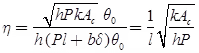
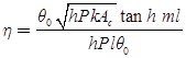
- For a fin of finite length with an insulated tip: ηf = tanh(m L) / (m L).
- For a very long fin (m L → ∞) the hyperbolic tangent tends to 1, hence the efficiency approaches ηf ≈ 1/(m L) when expressed per unit length; practically, as L → ∞ the lateral area becomes very large while q remains bounded, so ηf → 0 for an infinitely long fin when defined with Af = P L.
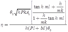
- For the case with convective tip the efficiency has a more complex form obtained by substituting the general q expression into ηf; the exact closed form expression depends on the ratio h/(m k) and is given in standard references.
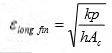
Fin Effectiveness
Fin effectiveness measures the improvement in heat transfer due to a fin compared with the same area without the fin, and is defined as
ε = q_actual / (h Ab θ₀),
where Ab is the area of the primary surface that the fin augments (for example the base area covered by one fin). A fin is considered useful when its effectiveness exceeds unity by a satisfactory margin.

For a long fin of uniform cross-section the heat transfer obtained and therefore the effectiveness can be expressed in closed form using the solutions shown earlier. For the insulated tip case the base heat rate is
q = √(h P k Ac) · θ₀ · tanh(m L),
and substituting into the definition of effectiveness with Ab (base area per fin) gives the standard effectiveness expression for that geometry.
Practical Notes on Fin Design and Selection
- Longer fins increase surface area and therefore can increase total heat transfer, but they also increase mass, cost and flow resistance. There is typically an optimum fin length for a given application.
- Fin efficiency decreases with increasing fin length because the fin temperature falls with distance from the base.
- To increase fin effectiveness and overall performance: use materials with higher thermal conductivity k; increase the ratio P / Ac (i.e., make thin, tall fins to increase perimeter per unit cross sectional area); and use fins in applications where the convective coefficient h is moderate or low (natural convection) where the relative benefit of increased area is larger.
Worked Example (Illustrative)
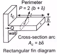
A straight aluminium fin of rectangular cross-section is attached to a hot wall at temperature T₀. The fin has thickness t, height into the page w (so Ac = t w) and length L in the x direction. Given k, h, P and Ac, determine the base heat transfer for an insulated tip.
Solution (derivation lines shown stepwise):
Define θ₀ = T₀ - T∞.
Compute m = sqrt(h P / (k Ac)).
For insulated tip the base heat rate is q = k Ac m θ₀ · tanh(m L).
Thus, evaluate m numerically from given k, h, P and Ac, then compute tanh(m L), then multiply to obtain q.
As m L becomes large (≫ 1), tanh(m L) → 1 and q → k Ac m θ₀ = √(h P k Ac) θ₀.
Summary
Fins (extended surfaces) are an economical means to increase convective heat transfer by increasing the surface area. The one-dimensional fin equation d²θ/dx² - m² θ = 0 with m² = h P/(k Ac) describes the excess temperature distribution for straight, prismatic fins with uniform properties. The three common tip boundary conditions (infinite length, insulated tip, convective tip) lead to closed-form solutions. Important performance measures are fin efficiency ηf = q/(h Af θ₀) and fin effectiveness ε = q/(h Ab θ₀). Practical fin design balances increased heat transfer against added mass, cost and flow friction; high thermal conductivity and high perimeter-to-area ratios improve fin performance.
FAQs on Heat Transfer Through Fins
| 1. What is heat transfer through fins? |  |
| 2. How do fins improve heat transfer? | |
| 3. What factors affect heat transfer through fins? | |
| 4. How can the effectiveness of fins be evaluated? | |
| 5. What are some common types of fins used in heat transfer applications? | |


