Types of Tension Members


Introduction
A tension member is a structural element that carries predominantly tensile force along its longitudinal axis. It is often called a tie or tie member. In many practical situations a tension member may also be subjected to bending due to eccentricity of the applied axial load or due to transverse loads acting in addition to the longitudinal force. Tension members are among the most commonly used structural elements and occur as minor members (for example bars, flats and rods) and as major members (for example members of roof and bridge trusses).
Minor Types of Tension Members
The common minor forms of tension members are illustrated in the figure below and are described thereafter.
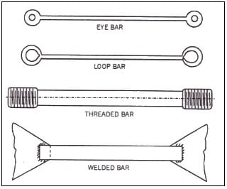 Fig. 1.
- Eye-bars. These are used where flexible end connections are required, typically in pin-connected truss bridges. Each end of a rectangular bar is upset to give an enlarged, approximately circular end in which a hole is bored to take a pin. The pin transmits the tensile force between the eye-bar and the other members meeting at the joint.
- Loop bars. These are made by bending each end of a bar (round or square) back on itself to form a loop which is then welded. Load transfer through the loop is similar to that of an eye-bar.
- Threaded bars. These are round bars with their ends threaded; nuts are fitted after erection. The ends are usually upset before threading so that the root area of the threads is at least equal to the gross bar area. After upsetting, the end cross-section is typically about 20% larger than the bar. For non-upset threaded bars the designer must ensure that the diameter at the root of the threads is adequate; a rule used in practice is that the root diameter should be at least 1.5 mm greater than the normally required bar diameter when upset ends are not provided.
- Welded bars. Flat bars carrying light tensile loads and welded at their ends are used where simple, economical connections are acceptable.
Major Types of Tension Members
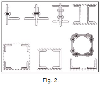
Major tension members are used where larger loads are transmitted, for example in roof trusses, bridge trusses and bracing systems. The principal types are described below; refer to the figure for typical cross-sections and connection arrangements.
Single angle tension members are commonly used in roof trusses for light loads and as bracings. When only one leg of an angle is bolted or riveted to the gusset plate, the resultant axial load is transferred eccentrically and the member is therefore subjected to bending as well as tension. This eccentricity must be considered in design.
Double angle members (angles placed back-to-back or toe-to-toe and connected on either side of a gusset plate) eliminate the eccentricity if the pair is connected symmetrically; this arrangement gives nearly concentric transfer of axial load to the gusset plate and hence the member is practically free from bending stress. Double channel sections may be used in a similar manner; these provide greater web depth and permit two or three rows of rivets, reducing the required length of the gusset plate.
For heavier loads, four-angle assemblies (with or without intermediate plate) or paired channel members are used. The major types are illustrated in the figure below.
Permissible Tensile Stress
Design of tension members is governed by the requirement that the tensile stress on the net effective section shall not exceed the permissible limit specified by the codes. According to the I.S. specification cited in the source material, the permissible axial tensile stress on the net effective area shall not exceed 0.6 fy, where fy is the minimum yield stress of the steel.
Example: If fy = 250 N/mm2, then permissible axial tensile stress = 0.6 × 250 = 150 N/mm2.
Net Sectional Area
The maximum tensile stress occurs at the section of minimum area. The net area of a tension member depends on the member type and the presence of holes for rivets, bolts or threads. The net area is determined as follows.
- Threaded rods: The area at the root of the threads is regarded as the net section.
- Riveted or bolted members: The net area at a section equals the gross area of the member at that section minus the area of the rivet or bolt holes cut out by that section.
When making deductions for rivet or bolt holes the following allowances are used for the hole diameter unless the specification gives a different value:
- For rivets or bolts of nominal diameter less than 25 mm, assume the hole diameter = nominal diameter + 1.5 mm.
- For rivets or bolts of nominal diameter greater than 25 mm, assume the hole diameter = nominal diameter + 2.0 mm.
Minimum net section: When several holes are present the minimum net section must be located by considering all possible failure paths (lines of rupture) through the plate. The following figures and discussion illustrate typical cases and the method of determining the minimum net effective width.
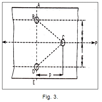
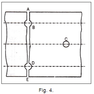
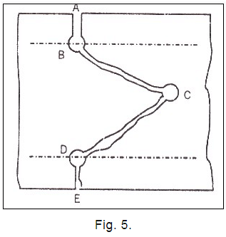
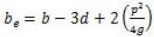
Consider a plate of gross width b, thickness t, carrying a pull P and provided with three rivet holes (labelled B, C and D). Possible failure paths include a straight line through two holes or a staggered (zigzag) line passing through alternate holes. For a failure along a straight section ABDE the net area equals the gross area minus the area of two rivet holes. For a failure along a staggered path ABCDE the effective net width may be less and should be calculated using the appropriate expression given by the code.
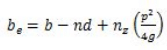
The variables in the expression are defined as:
- b = gross width of the plate
- n = number of rivet holes along a possible failure section
- nz = number of zigzag (staggered) lines along the potential line of failure
- p = staggered pitch (distance between successive rivets measured parallel to the direction of stress)
- g = gauge (distance between the same two consecutive rivets measured at right angles to the direction of stress)
Effective net area = be × t
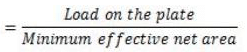
Maximum tensile stress in the plate = P / (be × t)
Net Effective Section for Angles and Tees in Tension
The rules for determining the net effective section of angles and tees in tension follow the I.S. specification summarised below.
(a) Single angles
For a single angle connected by one leg only (connected leg to the gusset plate), the net effective section is obtained by taking the effective area of the connected leg plus the gross area of the unconnected leg multiplied by a factor K (which accounts for the lever arm and distribution of stress). Thus:
The net effective section of the angle = A1 + A2 K
Where:
- A1 = effective cross-sectional area of the connected leg
- A2 = gross sectional area of the unconnected leg
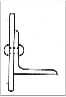 Fig. 6
(b) Double angles back-to-back and single tees
When two angles are used back-to-back and only one leg of each angle is connected to the same side of a gusset (or when a tee flange is connected), the net effective section is similarly taken as the effective area of the connected legs plus the gross areas of the unconnected legs multiplied by the same factor K:
The net effective section = A1 + A2 K
Where:
- A1 = effective cross-sectional area of the connected leg
- A2 = gross sectional area of the unconnected leg
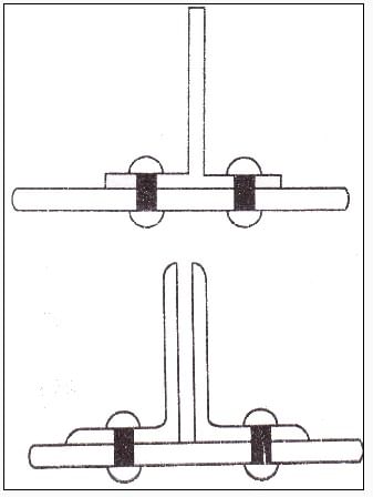 Fig. 7
The angles must be connected along their lengths by tacking or stitch rivets at a spacing not exceeding 32 times the thickness or 300 mm, whichever is less, to ensure composite action between the two angles.
- When the double angles are connected to opposite sides of a gusset plate, the area to be used in computing mean tensile stress shall be the full gross area minus the area of rivet holes; the angles shall be tacked together along their lengths.
- When double angles are not tack riveted together, each angle shall be designed as a single angle connected through one leg only.
For the purpose of area calculation, the area of the leg of an angle shall be taken as the product of its thickness and the length measured from the outer corner less half the thickness. The area of the leg of a tee shall be taken as the product of the thickness and the depth less the thickness of the flange.
Lug Angles
When a substantial number of rivets or bolts are required for the connection of a member to a gusset plate, the available length of the member may be largely occupied by the connection. To reduce the required length of the connection and the corresponding length of gusset plate, lug angles are often used. Lug angles are short angles attached to the member to provide additional rivet or bolt positions without increasing the length of the member that must be overlapped by the gusset plate.
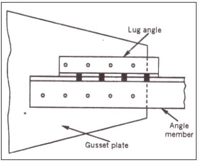 Fig. 8
Figure 8 shows a lug angle used to connect an angle member to a gusset plate. For connecting a channel section, two lug angles are commonly used as shown in the illustration below.
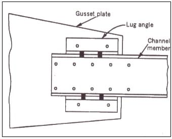 Fig. 9.
Design requirements for lug angles given in the specification include the following strength margins:
- For lug angles on angle members, the lug angles and their connections to the gusset shall be capable of developing a strength not less than 20% in excess of the force in the outstanding leg of the angle. The attachment of the lug angle to the angle member itself shall be capable of developing 40% in excess of that force.
- For lug angles on channel members, the lug angles and their connections to the gusset shall be capable of developing a strength not less than 10% in excess of the force not accounted for by the direct connection of the channel, and the attachment of the lug angles to the member shall be capable of developing 20% in excess of that force.
- In no case shall fewer than two bolts or rivets be used to attach a lug angle to the gusset or supporting member.
Conclusion
In the design of tension members the following practical points should be kept in mind:
- Always use the net effective area (after deductions for holes and staggered patterns) to compute tensile stress.
- Apply the code-specified allowances for hole diameters when making deductions for rivets and bolts.
- Consider possible eccentricities of connection and provide for bending effects in single-leg connections (single angles) where necessary.
- Use tacking or stitch rivets to ensure composite action of paired angles where recommended and limit their spacing as specified.
- Check lug angles and their attachments for the specified strength margins to ensure the connection does not control the design.
Careful attention to net area calculations, correct deduction for connections and proper detailing of connections (gusset plates, lugs, tacking rivets) ensures safe and economical tension members in steel structures.
FAQs on Types of Tension Members
| 1. What are the different types of tension members in civil engineering? |  |
| 2. How are tension members designed in civil engineering? | |
| 3. What are the key considerations for selecting tension members in civil engineering projects? | |
| 4. How are tension members inspected and maintained in civil engineering structures? | |
| 5. What are the challenges in designing tension members for extreme loading conditions in civil engineering? | |


