Fermat’s Principle | Oscillations, Waves & Optics - Physics PDF Download
| Table of contents |

|
| Introduction |

|
| Law of Reflection from Fermat Principle |

|
| Law of Refraction from Fermat Principle |

|
| Summary |

|
Introduction
“A ray of light traveling from one point to another by any number of reflections and refractions follows a path for which compared with all other neighboring paths, the time
taken is either a minimum or a maximum or stationary.” This is known as Fermat’s
Principle of stationary time or Fermat’s Principle of extremum path.
Law of Reflection from Fermat Principle
Law of Reflection from Fermat Principle
Let a ray of light travel from point A to B by the reflection at O from the mirror MM′
optical path from A to B
L = AO + OB = √a2 + x2 + √(c − x)2 + b2
From Fermat’s Principle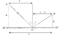


⇒sin i = sin r ⇒ i = r (This is law of reflection)
In addition, the incident ray, the surface normal an d reflected ray all lie in the same plane,
called the plane of incidence.
Law of Refraction from Fermat Principle
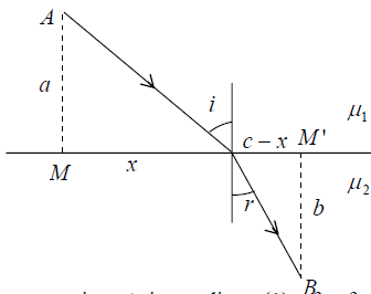
A light of ray from a point A in medium (1) of refractive index 1 μ be refracted to another point B in medium (2) of refractive index μ2 .
Optical path between A and B
L = μ1AO +μ2OB = μ1√a2 + x2 + μ2√(c-x)2+b2
From Fermat’s Principle:

⇒μ1 sin i = μ2 sin r
⇒ sin i / sin r = μ2 / μ1 = 1μ2 (Snell’s Law)
where 1μ2 is the refractive index of the second medium w.r.t. first.
Again the incidence ray, the surface normal and the refracted ray are in the same plane of
incidence.
Refraction and Reflection by spherical surfaces
We will first consider refraction at a spherical surface SPM separating two media of refractive indices n1 and n2 as shown in figure (a). Let C represent the center of curvature of the spherical surface. We will consider a point object O emitting rays in all directions. We will use Snell’s laws of refraction to determine the image of the point O .
We mention that not all rays emanating from O converge to a single point; however, if we consider only those rays which make small angles with the line joining the points O and C , then all rays do converge to a single point. This is known as the paraxial approximation, and according to Fermat’s principle all paraxial rays take the same amount of time to travel from O to I .
Now, in terms of the angles defined in figure (a), we have
∅1 = β +α1 and 2 2 ∅2 = β −α2
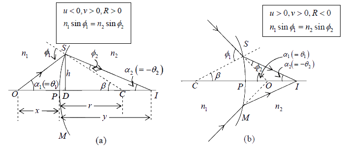
Figure: (a) Paraxial image formation by a spherical refracting surface separating media of refractive indices n1 and n2 . Point O represents the object point and I the paraxial image point. (b) Corresponds to positive u .

The Sign Convention
- The rays are always incident from the left on the refracting (or reflecting) surface.
- All distances to the right of the point P are positive, and distances to the left of the point P are negative.
- The angle that the ray makes with the axis is positive if the axis has to be rotated in the counterclockwise direction (through the acute angle) to coincide with the ray. Conversely, if the axis has to be rotated in the clockwise direction (through the acute angle) to coincide with the ray, then the slope angle is negative.
- The angle that a ray makes with the normal to the surface is positive if the normal has
- to be rotated in the counterclockwise direction (through the acute angle) to coincide with the ray, and conversely.
Reflection by a Single Spherical Surface
We next consider the image of a point object O by a spherical mirror SPM in the paraxial approximation; the point C represents the center of curvature.
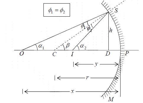
Figure: Paraxial image formation by a spherical reflecting surface SPM.
∅1 = β −α1 ≈ h/r − h/x and ∅2 =α2 − β ≈ h/y - h/r
where the distances x, y, h and r are defined in figure.
Since ∅1 =∅2 (the law of reflection), we get 
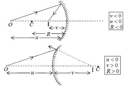
If we again use the sign convention that all the distances to the right of P are positive and those to its left negative, then u = −x,v = −y and R = −r thus we obtain the mirror
equation

The above relation is valid for both case give below.
Example 1: A spherical surface of radius of curvature R separates air (refractive index1.0 ) from glass (refractive index1.5 ). The centre of curvature is in glass. A point object P placed in air is found to have a real image Q in the glass. The line PQ cuts the surface at a point O and PO = OQ . Calculate the distance PQ in term of radius R.
By using
where μ1 =1,μ2 =1.5,u = −OP & v = OQ
(Since OP = OQ )
⇒
⇒ OP = 5R
Example 2: An air bubble in a glass sphere having 4 cm diameter appears1 cm from surface nearest to eye when looked along diameter. If 1.5 aμg = , then calculate the distance of bubble from refracting surface
By using
where u = ?, v = −1 cm, μ1 =1.5, μ2 =1 and R = −2 cm
⇒ u = -6/5 = -1.2 cm
u = −1.2 cm
Example 3: A thin rod of length f/3 lies along the axis of a concave mirror of focal length f. One end of its magnified image touches on end of the rod. What is the length of the image?
If end A of rod acts on object for mirror then its image will be formed at A′ .
End C remain unchanged and it is only possible if end C is placed at the centre of the
concave mirror.
Since Focal length OF = f ⇒OC = 2 f and u =
Now by using
∴Length of the image v is L =
Thin Lens
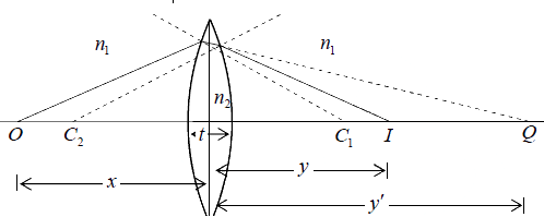
A medium bounded by two spherical refracting surfaces is referred to as a spherical lens. If the thickness of such a lens t (as shown figure) is very small compared to the object and image distances and to the radii of curvature of the refracting surfaces, then the lens is referred to as a thin spherical lens.
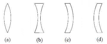
R1 > 0 R1 < 0 R1 < 0 R1 > 0
R2 < 0 R2 > 0 R2 < 0 R2 > 0
We consider a point object O on the axis of a (thin) lens as shown in figure. The lens is placed in a medium of refractive index n1 and the refractive index of the material of the lens is n2 . Let R1 and R2 be the radii of curvature of the left and right surfaces of the lens, respectively; then R1 is positive and R2 is negative. To determine the position of the
image, we will consider successive refractions at the two surfaces; the image formed by
the first surface is considered the object (which may be real or virtual) for the second surface. Thus, if the second refracting surface had not been there, the image of the point
O would have been formed at Q whose position (given by v′ ) is determined from the
following equation  (1)
(1)
where u is the object distance which is negative for the object point O shown in the figure. Obviously if v′ is positive, then the point Q lies to the right of the surface; and if
v′ is negative, then Q lies to the left of the surface. The point Q now acts as the (virtual)
object for the second refracting surface, and the final image is formed at I whose position
is determined from the equation  (2)
(2)
In equation (1) and (2) the distances are measured from the center of the lens P ; this is
justified because the lens has been assumed to be thin. Adding (1) and (2), we get
 (
( ) where n= n2/n1
where f known as the focal length of the lens.
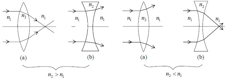
For a lens placed in air (which is usually the case), n >1 and if 
is a positive quantity, then the focal length is positive and the lens acts as a converging lens [see figure (a)]. Similarly if  is a negative quantity, then the lens acts as a
diverging lens [see figure (b)]. However, if the double convex lens is placed in a medium
whose refractive index is greater than that of the material of the lens, then the focal length becomes negative and the lens acts as a diverging lens [see figure (c)]; similarly for the double concave lens [see Fig. 3(d)].
The Principal Foci and Focal Lengths of a Lens
For a converging lens, the first principal focus is defined as the point (on the axis) such that a ray passing through that point will, after refraction through the lens, emerge parallel to the axis - see ray 1 in figure (a); the point F1 is the first principal focus. For a diverging lens, the ray which (in the absence of the lens) would have passed through the first principal focus emerges, after refraction by the lens, as a ray parallel to the axis- see ray 1 in figure (b). Point F1 is the first principal focus, and its distance from the lens (denoted by f1) is known as the first focal length of the lens. Obviously, f1 is negative for a converging lens and positive for a diverging lens.
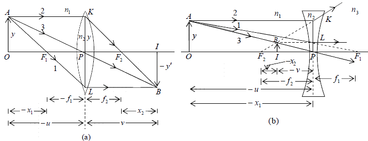
Figure: (a) Paraxial imaging by a converging lens; x1, f1 and u are negative quantities and x2,f2 and v are positive quantities. (b) Paraxial imaging by a diverging lens; here x1, x2, f2 ,u and v are negative quantities and f1 are positive quantities.
We next consider a ray which travels parallel to the axis [see ray 2 in figure (a) and (b)].
For a converging lens the point at which the ray will intersect the axis [shown as F2 in figure (a)] is known as the second principal focus of the lens.
For a thin lens placed in a medium such that the refractive indices on both sides of the lens are the same ( n3 = n1 ), the values of f1 and f2 can be readily obtained by considering the thin lens formula

However, if n3 ≠ n1 then the thin lens formula assumes the following form

Now, when v = ∞,u = − f1 (ray 1) and we have

Similarly, when u = −∞,v = f2 (ray 2), and we have
 =
= 
Once we know f1 and f2 (and therefore the positions of the first and second principal foci), the (paraxial) image can be graphically constructed from the following rules:
- A ray passing through the first principal focus will, after refraction, emerge parallel to the axis [see ray 1 in figure (a) and (b)].
- A ray parallel to the axis will, after refraction, either pass through or appear to come from (depending on the sign of f2) the second principal focus [see ray 2 in figure (a) and (b)].
The Newton Formula
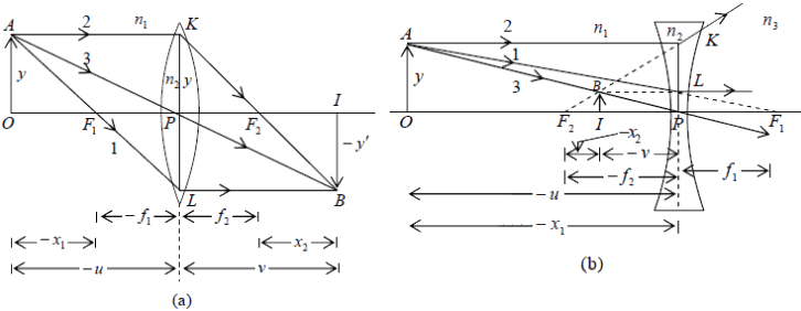
Let x1 be the distance of object from the first principal focus F1 ( 1 x will be positive if the object point is on the right of F1 and conversely), and let x2 be the distance of the image from the second principal focus F2 as shown in figure (a) and (b). Considering similar triangles in figure (a), we have 
where the vertical distances are positive if measured above the line and negative if below the line. Thus
f1f2 = x1x2
which is known as the Newtonian lens formula.
It may be noted that for a diverging lens [see figure (b)] 
When the thin lens has the same medium on the two sides, then
x1x2 = −f2
showing that x1 and x2 must be of opposite sign. Thus if the object lies on the left of the first principal focus, then the image will lie on the right of the second principal focus, and vice versa.
Magnification
The lateral magnification m is the ratio of the height of the image to that of the object.
Considering either figure (a) or figure (b), we readily get

Obviously, if m is positive, the image is erect [as in figure (b)], and conversely if m is negative, the image is inverted [as in figure (a)].
The magnification produced by a single refracting surface is given by

Considering triangles AOC and ICB , we get

Now, equation (5) gives us
 and
and 
Substance for and
and  , we get
Thus, if m1 and m2 represent the magnifications produced by the two refracting surfaces, then 
where v′ represents the distance of the image formed by the first refracting surface. Thus

Summary
Lateral (or linear) Transverse Magnification

Note:
(i) my is Positive for erect image and Negative for inverted image
(ii) my = v/u for same medium on both side.
Longitudinal Magnification
If the object and image have small extension dx1 and dx2 respectively along the axis, the ratio dx2/dx1 is called the longitudinal magnification.

mx = 
Angular magnification
If θ1 and θ2 be the angles which the incident and the corresponding emergent rays make with the principal axis then angular magnification
mθ = tanθ2 / tanθ1
⇒ mθ = u / v
I – relation
mx x mθ =  = my
= my
⇒ mx x mθ = my
i.e. Longitudinal magnification x Angular Magnification = Lateral Magnification.
II – Relation
mx = 
⇒mx ∝ m2y but f2 /f1 = constant
III – Relation

Example 4: A convex lens of focal length 25 cm and made of glass ( aμg = 1.5) is immersed in water ( aμw = 4/3). Calculate the change in the focal length of the lens.
⇒
Example 5: The radius of curvature of the convex face of a Plano- convex lens is 12cm and its μ =1.5.
(a) Find the focal length of the lens. The plane face of the lens is now silvered.
(b) At what distance from the lens will parallel rays incident on the convex surface converge?
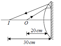
(c) Sketch the ray diagram to locate the image, when a point object is placed on the axis 20cm from the lens.
(d) Calculate the image distance when the object is placed as in (c).
(a):
or f1 = 24 cm
(b) When a face of the lens is silvered, it behaves as a concave mirror of effective focal length F given by
This means that the parallel rays will converge at a distance of 12cm from the silvered
surface.
(c) Figure illustrates the formation of the image.
(d) F = −12cm,u = −20cm
or v = −30cm
The negative sign shows that the image is real.
Example 6: A pin is placed 10cm in front of a convex lens of focal length 20cm and made of a material of refractive index1.5 . The surface of the lens farther away from the pin is silvered and has a radius of curvature of 22cm . Determine the position of the final image. Is the image real or virtual?
Since the convex lens with a silvered surface behaves as a concave mirror of effective
focal length F , we have F = -110 /21 cm and u = -10cm.
The negative sign shows that the image is in front of the effective mirror and hence is
real.
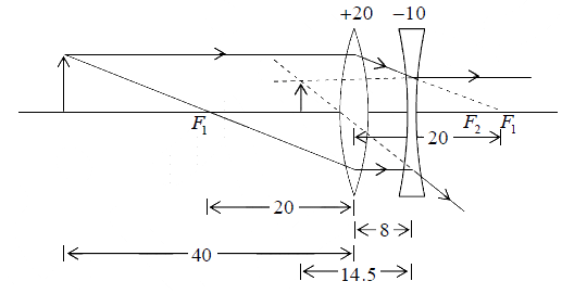
Example 7: Consider a system of two thin lenses as shown below. The convex lens has a focal length of +20 cm, and the concave lens has a focal length of −10 cm. The two lenses are separated by8 cm . For an object of height 1 cm (at a distance of 40 cm from convex lens), calculate the position and size of the image.
Let us first calculate the position and size of the image formed by the first lens:
u = −40 cm, f = +20 cm
⇒ v =+40 and m1 = −1; the image is of the same size but inverted. This image acts as a virtual object for the concave lens with u = +32 cm and f = +20 cm.
Thick Lens Formula

|
54 videos|22 docs|14 tests
|
FAQs on Fermat’s Principle - Oscillations, Waves & Optics - Physics
| 1. What is Fermat's principle? |  |
| 2. How does the law of reflection relate to Fermat's principle? |  |
| 3. Can Fermat's principle explain the law of refraction? |  |
| 4. How does Fermat's principle relate to the IIT JAM exam? |  |
| 5. Can you provide an example of how Fermat's principle can be applied in real-life situations? |  |

|
Explore Courses for Physics exam
|

|
 where μ1 =1,μ2 =1.5,u = −OP & v = OQ
 (Since OP = OQ )


