Interference of light | Oscillations, Waves & Optics - Physics PDF Download
Introduction
When the two waves of the same frequency travel in approximately the same direction
and have a constant phase difference the resultant intensity of the light is not distributed
uniformly in space. The non uniform distribution of light intensity due to superposition of
two waves is called interference.
At some points the intensity is a maximum and the interference at these points is called
constructive interference at some other points, the intensity is a minimum (possibly even
zero) and the interference at these points is called destructive interference.
Usually when two lights waves are made to interfere, we get alternate dark and bright
bands of a regular or irregular shape.
Young’s double slit Experiment
Purpose of this experiment is to demonstrate the fundamental properties of light
diffraction and interference patters.
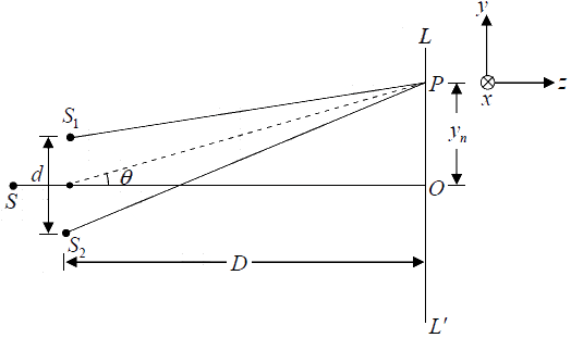
Let S1 and S2 represent the two pinholes of Young’s interference experiment. We want
to determine the positions of maxima and of minima on line LL′ !which is parallel to the
y axis and lies in the plane containing points S, S1 and S2 . We will show that the
interference pattern (around point O) consists of a series of dark and bright lines.
For an arbitrary point P (on line LL′ ) to correspond to a maximum or minima,
S2P − S1P = nλ
Now, (S2P)2 - (S1P)2 = 
= 2ynd
⇒ S2P − S1P = 
If yn, d << D , then negligible error will be introduced if S2P + S1P is replaced by 2D
S2P − S1P = 
Thus, the dark and bright fringes are equally spaced, and the distance between two
consecutive dark (or bright) fringes is given by
β = yn+1 - yn = λD/d, which is the expression for the fringe width.
The Intensity Distribution
Let E1 and E2 be the electric fields produced at point P by S1 and S2 , respectively. The
electric fields E1 and E2 will, in general, have different directions and different
magnitudes. However, if the distances S1P and S2P are very large in comparison to the
distance S1S2 , the two fields will almost be in the same direction. Thus, we may write


Where, ˆi represents the unit vector along the direction of either of the electric fields. The
resultant field is given by
E = E1 + E2 = 
The intensity I is proportional to the square of the electric field and is given by I = KE2

I = 
+ 
where K is a proportionality constant.
The factor cos (ωt −φ ) will oscillate between +1 and –1, and its average will be zero,
whereas average value of cos2 (ωt −φ ) is 1/ 2 .
Thus the intensity, that a detector will record, will be given by
I = I1 + I2 + 2√I1I2cosδ ,
where δ =  represents the phase difference between the displacements reaching point P from S1 and S2
Further I1 =  and I2 = 1/2KE202 represents the intensity produced by source S1 and from S2 on the screen.
Condition of Maximum Intensity
The maximum values of cosδ is +1. Therefore the maximum values of I is given by
Imax = 
The maximum intensity occurs when, Phase difference: δ = 2nπ ; n = 0,1,2,......
or Path difference: S2P − S1P = nλ
Condition of Minimum Intensity
The minimum values of cosδ is −1, as a result the minimum values of I is given by

The minimum intensity occurs when Phase difference: δ = (2n +1)π ; n = 0,1, 2,......
or Path difference: S2P − S1P = 
Intensity when S1P and S2P are extremely large
If the distances S1P and S2P are extremely large in comparison to d , then I1 ≅ I2 = I0
and
I = 2I0 + 2I0 cosδ = 4I0 cos2 δ / 2
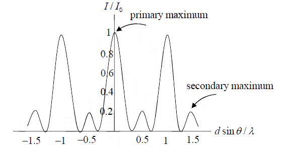
The intensity distribution is shown in below

Conditions for sustained Interference
- The two interfering waves should be coherent
- The two waves should be of same frequency
- If the interfering waves are polarized, they must be in the same state of polarization.
Conditions for observation
- The spacing between the light sources (d) should be as small as possible.
- The distance (D)of the screen from the two sources should be quite large.
Conditions for good contrast
- The amplitudes of the interfering waves should be equal or at least very nearly equal.
- The two sources must be narrow.
- The two sources should give monochromatic or very nearly monochromatic light, or else the path difference should be very small.
Example 1: Suppose in the double-slit arrangement, d = 0.150mm , D = 120cm, λ = 833nm, and y = 2.00cm.
(a) What is the path difference δ for the rays from the two slits arriving at point P?
(b) Express this path difference in terms of λ
(c) Does point P correspond to maximum, a minimum, or an intermediate condition?
(a) The path difference is given byδ = d sinθ . When D >> y,θ is small and we can make the approximation sinθ ≈ tanθ = y/D. Thus,
= 2.50 x 10⁻⁶m
(b) From the answer in part (a), we have
or δ = 3.00λ
(c) Since the path difference is an integer multiple of the wavelength the intensity at point
P is a maximum.
Example 2: In Young’s double-slit experiment, suppose the separation between the two slits is d = 0.320 mm. If a beam of 500 nm light strike the slits and produces an interference pattern. How many maxima will there be in the angular range −45.0o <θ < 45.0o ?
On the viewing screen, light intensity is a maximum when the two waves
interfere constructively. This occurs when
d sinθ = nλ, n = 0, ±1, ±2...
where λ is the wavelength of the light. Atθ = 45.0o , d = 3.20×10⁻⁴m and λ = 500×10−9m, we get n =
= 452.5
Thus, there are 452 maxima in the range0 <θ < 45.5o . By symmetry, there are also 452 maxima in the range −45.0o < θ < 0 . Including the one for n = 0 straight ahead, the total number of maxima is N = 452 + 452 + 1 = 905
Example 3: Let the intensity on the screen at a point P in a double slit interference pattern be 60.0% of the maximum value
(a) What is the minimum phase difference (in radians) between sources?
(b) In (a), what is the corresponding path difference if the wavelength of light is λ = 500nm?
(a) The intensity I=
where Imax is the maximum light intensity.
Thus, 0.60 cos2
⇒δ = 2cos−1(√0.60) = 78.5o =1.37 rad
(b) The phase difference δ is related to the path difference Δ and the wavelength λ by
Δ =
=
= 109nm
Intensity of Three Slit Interference
Suppose a monochromatic coherent source of light passes through three parallel slits,
each separated by a distance d from its neighbor, as shown in following Figure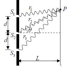
The waves have the same amplitude E0 and angular frequencyω , but a constant phase
difference δ = 
Example 4: Show that the intensity is I =  where I0 is the maximum intensity associated with the primary maxima.
(b) What is the ratio of the intensities of the primary and secondary maxima?
(a) Let the three waves emerging from the slits be
E1 = E0 sinωt, E2 = E0 sin ω t +δ, E3 = E0 sin ω t + 2δ
Using the trigonometric identity sinα + sinβ =
The sum of E1 and E3 is
E1 + E3 = E0[sinω t + sin ω t + 2δ] = 2E0 cosδ sin (ωt + δ)
The total electric field at the point P on the screen is
E = E1 + E2 + E3 = 2E0 cosδ sin(ωt +δ) + E0 sin (ωt +δ) = E0(1+ 2cosδ) sin (ωt + δ)
where δ =
The intensity is proportional to E2 , thus
=
∵
The maximum intensity I0 is attained when cosδ =1, thus I0 =
Thus,
(b) The interference pattern is shown in following figure
Form the figure, we see that the minimum intensity is zero, and occurs when cosδ = -1/2
The condition for primary maxima is cosδ = +1, which gives
In addition, there are also secondary maxima which are located at cosδ = −1. The
condition implies
δ = (2m+ 1)π
⇒
The intensity ratio is
Example 5: Consider the interference pattern from the three slits illustrated (shown in figure). Assume the openings of the individual slits are the same  .At what value of θ is the first principal maximum? (i.e., the wavelets from all three slits are in phase).
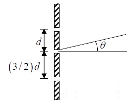
The electric field E(θ ) on the screen is the sum of the fields produced by the slits individually:
where
Then the total intensity at θ is
For θ = 0 , we have I (0) ~ 9A2 .
The expression for I (θ ) shows that the first principal maximum occurs at δ = 2π , i.e.,
Displacement of Fringes by the introduction of a thin Lamina Sheet
When a thin transparent plate, say of glass or mica, is introduced in the path of one of the
two interfering beams, the entire fringe-pattern is displaced to a point towards the beam
in the path of which the plate is introduced. Let a thin plate of thickness t be introduced in the path of light from S1 . 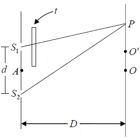 Let μ be the refractive index of the plate for the monochromatic light employed. Time taken for the journey from S1 to P

v0 = velocity of light in air &
v1 = velocity of light in plate
Hence the effective path in air from S1 to P is 
At any point P , effective path difference
=
For bright fringe 
In the absence of the plate t = 0 ;
Thus the displacement of nth fringe
This expression is independent of n so that the displacement of any dark fringe is also

What Are Interference Fringes?
- As laser light is diffracted through the two barrier slits, each diffracted wave meets the other in a series of steps, as illustrated in Figure 4 (and graphically in the interactive tutorial described above).
- Sometimes the waves meet in step (or in phase; constructive interference), sometimes they meet out of step (or out of phase; destructive interference), and sometimes they meet partially in step.
- When the waves meet in step, they add together owing to constructive interference, and a bright area is displayed on the screen.
- In areas where the waves meet totally out of step, they will subtract from each other owning to destructive interference, and a dark area will appear in that portion of the screen.
- The resulting patterns on the screen, a product of interference between the two diffracted beams of laser light, are often referred to as interference fringes.

- Other types of experiments have been devised to demonstrate the wave-like nature of light and interference effects.
- Most notable are the single mirror experiment of Humphrey Lloyd and the double mirror and biprism experiments devised by Augustin Fresnel.
Newton’s Rings Experiment
- Sir Isaac Newton, the famous 17th century mathematician and physicist, was one of the first scientists to study interference phenomena.
- In his famous Newton's Rings experiment, he placed a convex lens of large curvature radius on a flat glass plate and applied pressure to hold the lens and glass plate together.
- When he viewed the plates through reflected sunlight, he observed a series of concentric light and dark highly colored bands of light similar to those illustrated in Figure 5.
- Newton recognized that the rings indicated the presence of some degree of periodicity and used this observation to suggest a wave theory of light.
- Despite this, Newton regarded light as a stream of particles.
 The rings occur because of a thin layer of air that exists between the curved convex and flat glass surfaces.
 - Light reflected from the top and bottom surfaces of the glass is superimposed (combined) and produces interference patterns that appear as colored rings.
- This principle is often used by lens manufacturers to test the uniformity of large polished surfaces.
|
54 videos|22 docs|14 tests
|
FAQs on Interference of light - Oscillations, Waves & Optics - Physics
| 1. What is Young's double slit experiment? |  |
| 2. How does the intensity distribution in Young's double slit experiment vary? |  |
| 3. What is the condition for maximum intensity in Young's double slit experiment? |  |
| 4. What is the condition for minimum intensity in Young's double slit experiment? |  |
| 5. How does the introduction of a thin lamina sheet affect the fringes in Young's double slit experiment? |  |


