Kirchhoff’s Law | Electricity & Magnetism - Physics PDF Download
➤ Kirchhoff’s Voltage Law (KVL)
Kirchhoff’s voltage law states that the voltage applied to a closed circuit equals the sum of the voltage drops in that circuit. In series circuits it can be expressed as follows:
Voltage applied = sum of voltage drops
VA = V1 + V2 + V3
where VA is the applied voltage and V1, V2 and V3 are voltage drops.
Another way of stating KVL is that the algebraic sum of the voltage rises and voltage drops must be equal to zero. A voltage source or emf is considered a voltage rise; a voltage across a resistor is a voltage drop.
Voltage applied – sum of voltage drops = 0
Substitute letters: VA – V1 – V2 – V3 = 0 or VA – (V1 + V2 + V3) = 0
Using a symbol, Σ, we have
ΣV = VA – V1 – V2 – V3 = 0
in which ΣV, the algebraic sum of all the voltages around any closed circuit, equals zero.
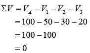
We assign a + sign to a voltage rise and a – sign to a voltage drop for the ΣV = 0 formula (as shown in figure below). In tracing voltage drops around a circuit, start at the negative terminal of the voltage source. The path from the negative terminal to the positive terminal of the source is voltage rise. In figure if we start at point a, the negative terminal of the battery, and move around the circuit in the direction abcda, we go through VA from – to + and VA = +100V. If we start at point b and move in the opposite direction badcb, we go through VA from + to – and VA = –100 V. The voltage drop across any resistance will be negative (-) if we trace it in the + to – direction. Thus in figure, if we trace the circuit in the direction abcda, V1 = –50V, V2 = –30V and V3 = –20V. The voltage drop will be positive (+) if we go through the resistance in the – to + direction. So in tracing the circuit in the direction abcda, we have
ΣV = VA – V1 – V2 – V3 = 0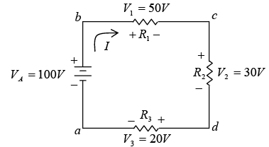 Illustration of ΣV = 0
➤ Kirchhoff’s Current Law (KCL)
Kirchhof’s current law states that the sum of the currents entering a junction is equal to the sum of the currents leaving the junction. Suppose we have six currents leaving and entering a common junction or point, shown as P. This common point is also called a node.
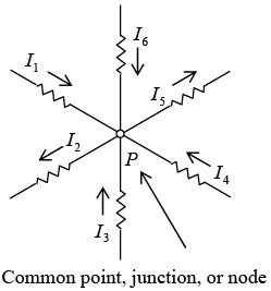 Currents at a common point
Substitute letters:
I1 + I3 + I4 + I6 = I2 + I5
If we consider that the currents flowing toward a junction are positive (+) and those currents flowing away from the same junction are negative (-), then this law also states that the algebraic sum of all the currents meeting at a common junction is zero. Using the symbol Σ, we have
Σ I = 0
where ΣI, the algebraic sum of all the currents at the common point is zero.
I1 – I2 + I3 + I4 – I5 + I6 = 0
If the negative terms are transposed to the right side of the equal sign, we would have the same form as the original equation.
➤ Mesh Current
A simplification of Kirchhoff’s laws is a method that makes use of mesh or loop currents. A mesh is any closed path of a circuit. It does not matter whether the path contains a voltage source. In solving a circuit with mesh currents, we first must decide which paths will be the meshes. Then we assign a mesh current to each mesh. For convenience, mesh currents are usually assigned in a clockwise direction. Kirchhoff’s voltage law is then applied about the path of each mesh. The resulting equations determine the unknown mesh currents. From these currents, the current or voltage of any resistor can be found.
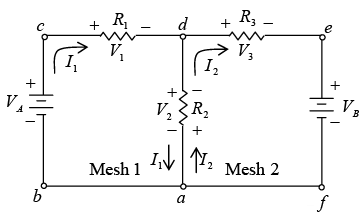 Two-mesh circuit
In figure shown above, we have a two-mesh circuit marked mesh 1 and mesh 2. Mesh 1 is path abcda and mesh 2 is path adefa. All voltage sources and resistances are known. A procedure for finding mesh currents I1 and I2 is as follows:
Step 1: After the meshes are selected, show the direction of mesh currents I1 and I2 in a clockwise direction. Mark the voltage polarity across each resistor, consistent with the assumed current. Remember that conventional current flow in a resistor produces positive polarity where the current enters.
Step 2: Apply Kirchhoff’s voltage law, ΣV = 0, around each mesh. Trace each mesh in the direction of mesh current. Note that there are two different currents (I1, I2) flowing in opposite directions through the same resistor, R2, which is common to both meshes. For this reason two sets of polarities are shown by R2 (as shown in figure). Trace mesh 1 in direction abcda.
+VA – I1R1 – I1R2 + I2R2 = 0
+VA – I1 (R1 + R2) + I2R2 = 0
or + I1 (R1 + R2) – I2R2 = VA …..(1)
Note that in the first expression I2R2 is + since we go through a voltage drop from – to +. Trace mesh 2 in direction adefa.
– I2R2 + I1R2 –I2R3 – VB = 0
+ I1R2 – I2 (R2 + R3) = VB …..(2)
Note that I1R2 is a + voltage drop since we go through a voltage drop from – to +.
Step 3: Find I1 and I2 by solving equations (1) and (2) simultaneously.
Step 4: When mesh currents are known, find all resistor voltage drops by using Ohm’s law.
Step 5: Check the solution of mesh currents by tracing mesh abcdefa.
VA – I1R1 – I2R3 – VB = 0
Alternating Current
➤ Sine Wave
The instantaneous value of voltage at any point on the sine wave is expressed by the equation v = VMsinθ
where v = instantaneous value of voltage, V , VM = maximum value of voltage, Vθ = angle
➤ Alternating Current
When a sine wave of alternating voltage is connected across a load resistance, the current that flows in the circuit is also a sine wave as shown in figure below.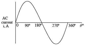 One cycle of alternating current➤ Frequency and Period
The number of cycles per second is called frequency. It is indicated by the symbol f and is expressed in hertz (Hz). One cycle per second equals one hertz. Thus 60 cycles per second (sometimes abbreviated cps) equals 60 Hz. A frequency of 2 Hz (figure b) is twice the frequency of 1 Hz (figure a).
 Comparison of frequencies The amount of time for the completion of 1 cycle is the period. It is indicated by the symbol T for time and is expressed in seconds (s). Frequency and period are reciprocals of each other
The higher the frequency, the shorter the period.
The angle of 360° represents the time for 1 cycle, or the period T. So we can show the horizontal axis of the sine wave in units of either electrical degrees or seconds.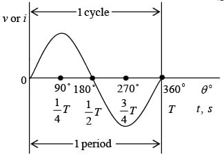 Relationship between electrical degrees and time
The wavelength λ is the length of one complete wave or cycle. It depends upon the frequency of the periodic variation and its velocity of transmission. Expressed as a formula,
For electromagnetic radio waves, the velocity in air or a vacuum is 3 × 10⁸ m/s, which is the speed of light.
λ = c/f
where λ = wavelength, m , c = speed of light 3 × 10⁸ m/s, a constant, f = radio frequency, Hz
➤ Phase Relationships
The phase angle between two waveforms of the same frequency is the angular difference at a given instant of time. As an example, the phase angle between waves B and A (figure a) is 90°. Take the instant of time at 90°. The horizontal axis is shown in angular units of time. Wave B starts at maximum value and reduces to zero value at 90°, while wave A starts at zero and increases to maximum value at 90°. This 90° phase angle between waves B and A is maintained throughout the complete cycle and all successive cycles. At any instant of time, wave B has the value that wave A will have 90° later. Wave B is a cosine wave because it is displaced 90° from wave A, which is a sine wave. Both waveforms are called sinusoids.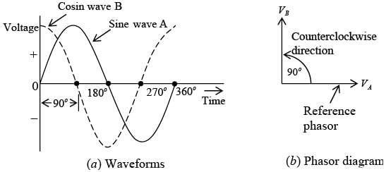
➤ Phasors
To compare phase angles or phases of alternating voltages and currents, it is more convenient to use phasor diagrams corresponding to the voltage and current waveforms. A phasor is a quantity that has magnitude and direction. The terms phasor and vector are used for quantities that have direction. However, a phasor quantity varies with time, while a vector quantity has direction in space. The length of the arrow in a phasor diagram indicates the magnitude of the alternating voltage. The angle of the arrow with respect to the horizontal axis indicates the phase angle. One waveform is chosen as the reference. Then the second waveform can be compared with the reference by means of the angle between the phasor arrows. For example, the phasor VA represents the voltage wave A with a phase angle of 0° (figure b as shown above). The phasor VB is vertical to show the phase angle of 90° with respect to phasor VA, which is the reference. Since lead angles are shown in the counterclockwise direction from the reference phasor, VB leads VA by 90°.
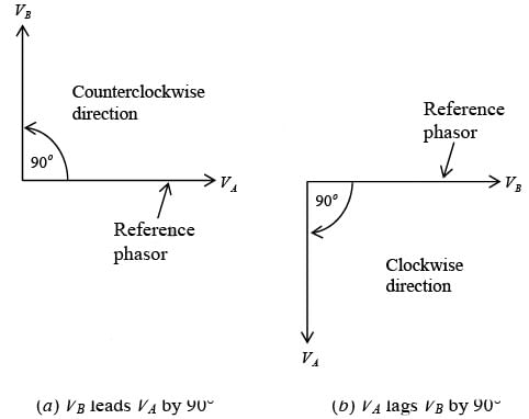 Leading and lagging phase anglesGenerally, the reference phasor is horizontal corresponding to 0°. If VB were shown as the reference, VA would have to be 90° clockwise in order to have the same phase angle. In this case VA lags VB by 90°. There is no fundamental difference between VB leading VA by 90° (figure a as shown below) or VA lagging VB by 90° (figure b as shown above). When two waves are in phase (figure a as shown below), the phase angle is zero. Then the amplitudes add (figure b as shown below).
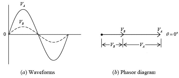 Two waves in phase with angle of 0o
When two waves are exactly out of phase (figure a as shown below), the phase angle is 180°. Their amplitudes are opposing (figure b as shown below). Equal values of opposite phase cancel each other.
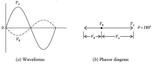 Two waves in opposite phase with angle of 180o
➤ Characteristic Value of Voltage and Current
Since an ac sine wave voltage or current has many instantaneous values throughout the cycle, it is convenient to specify magnitudes for comparing one wave with another. The peak, average or root-mean-square (rms) value can be specified. These values apply to current or voltage.
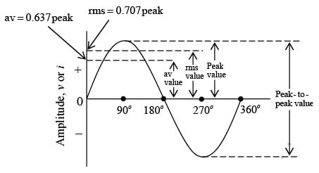 Amplitude values for ac sine wave
The peak value is the maximum value VM or IM. It applies to either the positive or negative peak. The peak-to-peak (p-p) value may be specified and is double the peak value when the positive and negative peaks are symmetrical.
The average value is the arithmetic average of all values in a sine wave for 1 half-cycle.
The half-cycle is used for the average because over a full cycle the average value is zero.
Average value = 0.637 × peak value
or
Vav = 0.637 VM
Iav = 0.637 IM
The root-mean-square value or effective value is 0.707 times the peak value.
RMS value = 0.707 × peak value
or
Vrms = 0.707 VM
Irms = 0.707 IM
The rms value of an alternating sine wave corresponds to the same amount of direct current or voltage in heating power. An alternating voltage with an rms value of 115 V, for example, is just as effective in heating the filament of a light bulb as 115 V from a steady dc voltage source. For this reason, the rms value is also called the effective value.
Unless indicated otherwise, all sine wave ac measurements are given in rms values. The letters V and I are used to denote rms voltage and current. For instance, V = 220 V (an ac power line voltage) is understood to mean 220 V rms. Use Table given below as a convenient way to convert from one characteristic value to another.
Use Table given below as a convenient way to convert from one characteristic value to another.
Table: Conversion Table for AC Sine Wave Voltage and Current 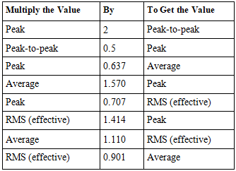
Resistance in AC Circuits In an ac circuit with only resistance, the current variations are in phase with the applied voltage (as shown in figure below). This in-phase relationship between V and I means that such an ac circuit can be analyzed by the same methods used for dc circuits. Therefore, Ohm’s laws for dc circuits are applicable also to ac circuits with resistance only. The calculations in ac circuits are generally in rms values, unless otherwise specified. For the series circuit, I = V/R = 110/10 = 11 A. The rms power dissipation is P = I2R = 112(10) = 1210 W.
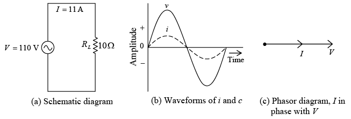 AC circuit with only resistance
|
82 videos|29 docs|22 tests
|
FAQs on Kirchhoff’s Law - Electricity & Magnetism - Physics
| 1. What is Kirchhoff's Law? |  |
| 2. How are Kirchhoff's Laws applied in circuit analysis? |  |
| 3. Can Kirchhoff's Laws be applied to both DC and AC circuits? |  |
| 4. What are the limitations of Kirchhoff's Laws? |  |
| 5. How can Kirchhoff's Laws be used to solve complex circuits? |  |

|
Explore Courses for Physics exam
|

|


