Superposition of Waves | Oscillations, Waves & Optics - Physics PDF Download
Superposition of Two Disturbances and Production of Polarized Wave
Superposition of Two Waves with Parallel Electric Field
Let us consider the propagation of two linearly polarized electromagnetic waves (both
propagating along the z axis) with their electric vectors oscillating along the x axis. The
electric fields associated with the waves can be written in the form
E1 = xˆa1 cos (kz −ω t +θ1) (1)
E2 = xˆa2 cos (kz −ω t +θ2) (2)
where a1 and a2 represent the amplitudes of the waves, ˆx represents the unit vector
along the x axis, and θ1 and θ2 are phase constants. The resultant of these two waves is
given by
E = E1 + E2 (3)
which can always be written in the form
E = xˆa cos (kz −ω t +θ ) (4)
where  (5)
(5)
represents the amplitude of the wave. Equation (4) tells us that the resultant is also a
linearly polarized wave with its electric vector oscillating along the same axis.
Superposition of Two Waves with Mutually Perpendicular Electric field
We next consider the superposition of two linearly polarized electromagnetic waves (both
propagating along the z axis) but with their electric vectors oscillating along two
mutually perpendicular directions. Thus, we may have
E1 = xˆa1 cos kz −ωt (6)
E2 = yˆa2 cos kz −ωt +θ (7)
For θ = nπ , the resultant will also be a linearly polarized wave with its electric vector
oscillating along a direction making a certain angle with the x axis; this angle will
depend on the relative values of a1 and a2 .
To find the state of polarization of the resultant field, we consider the time variation of
the resultant electric field at an arbitrary plane perpendicular to the z axis which we may,
without any loss of generality, assume to be z = 0 .
If Ex and Ey represent the x and y components of the resultant field E = (E1 + E2) , then
Ex = a1 cosωt (8)
and Ey = a2cos(ωt - θ) (9)
where we have used Equations (6) and (7) with z = 0 .
For θ = nπ the above equations simplify to
Ex = a1 cosωt and Ey = (-1)na2cosωt (10)
from which we obtain  (independent of t) (11)
where the upper and lower signs correspond to n even and n odd, respectively. In the
Ex Ey plane, Eq. (11) represents a straight line; the angle φ that this line makes with the
Ex axis depends on the ratio a2/a1 In fact φ =  (12)
(12)
The condition θ = nπ implies that the two vibrations are either in phase (n = 0, 2, 4....) or
out of phase (n =1,3,5,...) . Thus, the superposition of two linearly polarized
electromagnetic waves with their electric fields at right angles to each other and
oscillating in phase is again a linearly polarized wave with its electric vector, in general,
oscillating in a direction which is different from the fields of either of the two waves.
Following figures shows the plot of the resultant field corresponding to Eq. (10) for various values of a2/a1 . The tip of the electric vector oscillates (with angular frequency ω) along the thick lines shown in the figure. The equation of the straight line is given by Eq. (11).
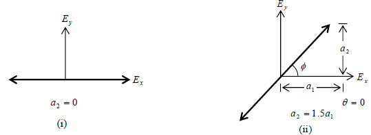
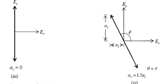
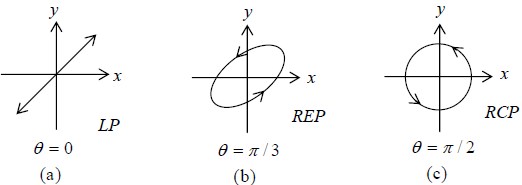
For θ ≠ nπ (n = 0,1, 2,...), the resultant electric vector does not, in general, oscillate along a straight line. We first consider the simple case corresponding to θ = π/2 with a1 = a2 Thus,
Ex = a1cos ωt (13) and Ey = a1cos ωt (14)
If we plot the time variation of the resultant electric vectors whose x and y components
are given by Eqs. (13) and (14), we find that the tip of the electric vector rotates on the
circumference of a circle (of radius 1 a ) in the counterclockwise direction as shown in
Fig. (c) below, and the propagation is in the +z direction which is coming out of the page. Such a wave is known as a right circularly polarized wave (usually abbreviated as a RCP wave). That the tip of the resultant electric vector should lie on the circumference of circle is also obvious from the fact that
Ex2 + Ey2 = a12 (Independent of t )
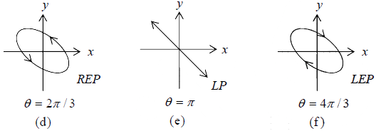
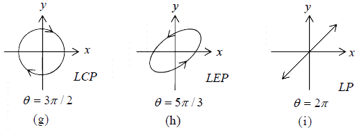
For θ = 3π/2, Ex = a1cos ωt (15) and
Ey = -a1sin ωt (16)
which would also represent a circularly polarized wave; however, the electric vector will
rotate in the clockwise direction [Fig. (g)]. Such a wave is known as a left circularly
polarized wave (usually abbreviated as a LCP wave).
the tip of the electric vector rotates on the circumference of an ellipse. As can be seen from the figure, this ellipse will degenerate into a straight line or a circle when θ becomes an even or an odd multiple of π/2 . In general, when a1 ≠ a2 , one obtains an elliptically polarized wave which degenerates into a straight line for θ = 0,π ,2π ,... etc.
The Phenomenon of Double Refraction
When an unpolarized light beam is incident normally on a calcite crystal, it would in general, split up into two linearly polarized beams as shown in Fig. (a). The beam which
travels undeviated is known as the ordinary ray (usually abbreviated as the o − ray) and
obeys Snell’s laws of refraction. On the other hand, the second beam, which in general
does not obey Snell’s laws, is known as the extraordinary ray (usually abbreviated as the
e − ray).
The appearance of two beams is due to the phenomenon of double refraction, and a
crystal such as calcite is usually referred to as a double refracting crystal. If we put a
Polaroid PP′ behind the calcite crystal and rotate the Polaroid (about NN′ ), then for two
positions of the Polaroid (when the pass axis is perpendicular to the plane of the paper)
the e - ray will be completely blocked and only the o-ray will pass through.

Fig (a) When an unpolarized light beam is incident normally on a calcite
crystal, it would in general, split up into two linearly polarized beams. (b) If we rotate the
crystal about NN′ then the e-ray will rotate about NN′ .
On the other hand, when the pass axis of the Polaroid is in the plane of the paper (i.e.,
along the line PP′ ), then the o - ray will be completely blocked and only the e-ray will
pass through. Further, if we rotate the crystal about NN′ then the e -ray will rotate about
the axis [see Fig. (b)].
The velocity of the ordinary ray is the same in all directions, the velocity of the extraordinary ray is different in different directions; a substance (such as as calcite, quartz) which exhibits different properties in different directions is called an anisotropic substance. Along a particular direction (fixed in the crystal), the two velocities are equal; this direction is known as the optic axis of the crystal. In a crystal such as calcite, the two rays have the same speed only along one direction (which is the optic axis); such crystals are known as uniaxial crystals. The velocities of the ordinary and the extraordinary rays are given by the following equations:
 (Ordinary ray) and
  (extraordinary)
where no and ne are refractive index for O- ray and e - ray and θ is the angle that the ray
makes with the optic axis; we have assumed the optic axis to be parallel to the z axis.
Thus, c/no and c/ne are the velocities of the extraordinary ray when it propagates parallel
and perpendicular to the optic axis.
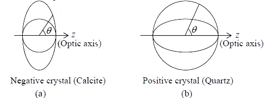
Fig. (a) In a negative crystal, the ellipsoid of revolution (which corresponds to the extra
ordinary ray) lies outside the sphere; the sphere corresponds to the ordinary ray. (b) In a
positive crystal, the ellipsoid of revolution (which corresponds to the extraordinary ray)
lies inside the sphere.
Quarter Wave Plate and Half Wave Plate
Let electric field vector (of amplitude E0 ) associated with the incident linearly polarized
beam makes an angle φ with optic axis which is parallel to z-axis and incident on calcite
crystal of thickness d whose optic axis is parallel to the surface

Such beam while traveling in calcite crystal splits into two components. The z-axis whose
amplitude is E0 cosφ passes through as an extraordinary ray (e-ray) propagates with
velocity c/ne . The y-axis whose amplitude is 0 E sinφ passes through as an ordinary ray
(o-ray) propagates with velocity c/no .
Since no ≠ ne the two beams will propagate with different velocities, thus when they
come out of the crystal, they will not be in phase. Let on the plane x = 0 , the beam is
incident then
Ey = E0sinφcos(kx −ωt) and Ez = E0cosφcos(kx −ωt)
Thus at x = 0 , we have
Ey = E0sinφcosωt and Ez = E0cosφcosωt
Inside crystal the two components will be
Ey = E0sinφcos(nokx −ωt) and Ez = E0cosφcos(nekx −ωt)
If thickness of the crystal is d then on emerging surface we have
Ey = E0sinφcos(nokd −ωt) and Ez = E0cosφcos(nekd −ωt)
Thus the phase difference between e-ray and o-ray is δ = kd(no - ne)
If phase difference isδ =π / 2 , then d= λ/4(no - ne)(Quarter Wave Plate)
If phase difference isδ =π , then d= λ/2(no - ne)(Half Wave Plate)
Wollaston Prism
A Wollaston prism is used to produce two linearly polarized beams. It consists of two
similar prisms (calcite) with the optic axis of the first prism parallel to the surface and the
optic axis of the second prism parallel to the edge of the prism as shown below. Let us
first consider the incidence of a z polarized beam as shown in Fig. (a). The beam will
propagate as an o − ray in the first prism (because the vibrations are perpendicular to the
optic axis) and will see the refractive index n0 . When this beam enters the second prism,
it will become an e -ray and will see the refractive index ne . For calcite no > ne and the
ray will bend away from the normal. Since the optic axis is normal to the plane of paper,
the refracted ray will obey Snell’s laws, and the angle of refraction will be given by
nosin 20o = nesinr1
where we have assumed the angle of the prism to be 20o . Assuming no ≈ 1.658 and
ne ≈ 1.486 , we readily get r1 ≈ 22.43o
Thus the angle of incidence at the second surface is i1 = 22.43o − 20o = 2.43o . The output angle θ1 is given by nesin 2.43o = sinθ1⇒ θ1 = 3.61o

We next consider the incidence of a y - polarized beam as shown in Fig. (b). The beam
will propagate as an e -ray in the first prism and as an o -ray in the second prism. The
angle of refraction is now given by
nesin20 = nosinr2 ⇒ r2 ≈ 17.85o
Thus the angle of incidence at the second interface is
i2 = 20o −17.85o = 2.15o
The output angle θ2 is given by
nosin2.15o = sinθ2 ⇒ θ2 ≈ 3.57o
Thus, if an unpolarized beam is incident on the Wollaston prism, the angular separation
between the two orthogonally polarized beams is θ =θ1 +θ2 ≈ 7.18o .
Rochon Prism
We next consider the Rochon prism which consists of two similar prisms of (say) calcite;
the optic axis of the first prism is normal to the face of the prism while the optic axis of
the second prism is parallel to the edge as shown in figure. Now, in the first prism both
beams will see the same refractive index no ; this follows from the fact that the ordinary
and extraordinary waves travel with the same velocity  along the optic axis of the
crystal. When the beam enters the second crystal, the ordinary ray (whose D is normal to
the optic axis) will see the same refractive index and go undeviated as shown in figure. On the other hand, the extraordinary ray (whose D is along the optic axis) will see the refractive index ne and will bend away from the normal.
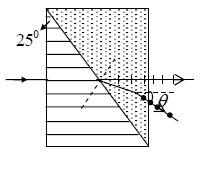
We assume the angle of the prism to be 25o . The angle of refraction will be determined from
nosin25o = nesinr
This sinr =  = 1.658/1.486 x 0.423 ≈ 0.472 ⇒r = 28.2o
Therefore the angle of incidence at the second surface will be 28.2o − 25o = 3.2o . The
emerging angle will be given by sinθ = nesin (3.2o) ⇒θ ≈ 4.8o
Example 1: Light strikes a water surface at the polarizing angle. The part of the beam refracted into the water strikes a submerged glass slab (index of refraction,1.50 ), as shown in Figure. The light reflected from the upper surface of the slab is completely polarized. Find the angle between the water surface and the glass slab.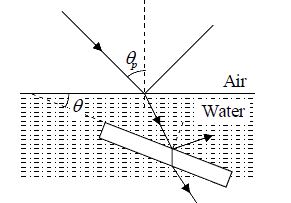
For the air-to-water interface,
(θp= 53.1o)
and (1.00)sinθp = (1.33)sinθ2
For the water to glass interface,
⇒ θ2 = 48.4o
The angle between surfaces is θ = θ3 - θ2 = 11.5o
Example 2: Plane- polarized light is incident on a single polarizing disk with the direction of E0 parallel to the direction of the transmission axis. Through what angle should the disk be rotated so that the intensity in the transmitted beam is reduced by a factor of
(a) 3.00, (b) 5.00, (c) 10,0?
I = Imaxcos2θ ⇒ θ =
(a)
⇒ θ =
= 54.7o
(b)
⇒ θ =
= 63.4o
(c)⇒ θ =
= 71.6o
Example 3: In figure below, suppose that the transmission axes of the left and right
polarizing disks are perpendicular to each other, also, let center disk be rotated on the common axis with an angular speedω . Show that if unpolarized light is incident on the left disk with intensity Imax of the beam emerging from right disk is

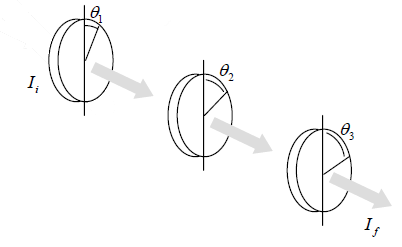
For incident unpolarized light of intensity Imax :
After transmitting 1st disk:
After transmitting 2nd disk:
After transmitting 3rd disk:
Where the angle between the first and second disk is θ =ω t
Using trigonometric identities cos2θ = 1/2(1 + cos2θ)
Ans cos2(90o - θ) = sin2θ = 1/2(1-cos2θ)
We have
since θ =ω t , the intensity of the emerging beam is given by
Example 4: A half-wave plate and a quarter-wave plate are placed between a polarizer P1 and an analyzer P2 . All of these are parallel to each other and perpendicular to the direction of propagation of unpolarized incident light (see the figure). The optic-axis of the half-wave plate makes an angle of 30o with respect to the pass-axis of P1 and that of the quarter-wave plate is parallel to the pass-axis of P1 .
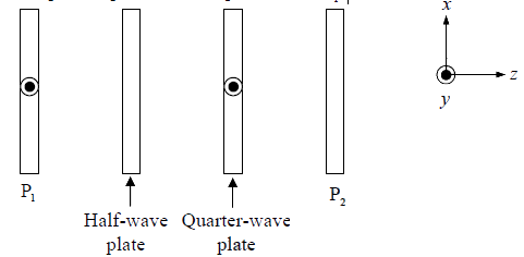
(a) Determine the state of polarization for the light after passing through (i) the half- wave plate and (ii) the quarter-wave plate.
(b) What should be the orientation of the pass-axis of P2 with respect to that of P1 such that the intensity of the light emerging from P2 is maximum?
(a) After passing through HWP the incident ray will split into an o -ray of
amplitude E0sin30o = E0/2 and of e-ray of amplitude E0cos30o = E0√3/2. After emerging out of HWP they will have phase difference ofπ . Superposition of these o -
and e -ray will produce linearly polarized light at the output of HWP. The electric field components of o -ray and e -ray at the output of HWP is
=
=
The electric field components of linearly polarized light at the output of HWP is
The optic axis of QWP is parallel to the 1 P i.e along x -axis. The electric field component of incident linearly polarized light makes zero angle with the optic axis as a result the incident light will simply pass through QWP as a e -ray. Therefore at the output of the QWP light will be linearly polarized with the equation

(b) The orientation of the pass axis of P2 should be parallel to the pass axis of P1 to allow maximum intensity of light to pass through P2.
Example 5: Two orthogonally polarized beams (each of wavelength 0.5 μm and with
polarization marked in the figure) are incident on a two-prism assembly and emerge
along x -direction, as shown. The prisms are of identical material and o n and e n are the refractive indices of the o -ray and e -ray, respectively. Use  and no =
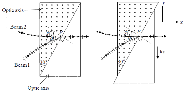
(a) Find the value of θ and ne . (b) If the right hand side prism starts sliding down with the vertical component of the velocity uy = 1μm/ s , what would be the minimum time after which the state of polarization of the emergent beam would repeat itself?
(a) The beam will propagate as an o − ray in the first prism (because the vibrations are
perpendicular to the optic axis) and will see the refractive index no . When this beam
enters the second prism, it will become an e − ray and will see the refractive index e n . For calcite no > ne and the ray will bend away from the normal. Since the optic axis is
normal to the plane of, the refracted ray will obey Snell’s laws, and the angle of refraction will be given by n0sin30o = nesinθ We next consider the incidence of a second beam. The beam will propagate as an e − ray in the first prism and as an o −ray in the second prism. The angle of refraction is now given by nesin30o = nosinθ
⇒
⇒
From 1st equation n0sin30o = nesinθ ⇒
sin2θ = 3/4 ⇒ sinθ = √3/2 ⇒ θ = 60o
Hence ne =
(b) The state of polarization will repeat if change in phase difference (δ ) is π .
The relation between phase difference and path difference (Δ) is δ = 2π/λx Δ
Where, Δ = (no - ne)d = (no - ne) x 10-6x t
Thus δ = 2π/λx Δ =
= π ⇒ t =
.
While no - ne =
=
Thus t =
=
= 0.85 sec
Analysis of Polarized Light
- Linearly polarized
- Circularly polarized
- Elliptically polarized
- Unpolarized
- Mixture of linearly polarized and unpolarized
- Mixture of circularly polarized and unpolarized
- Mixture of elliptically polarized and unpolarized light
If we introduce a Polaroid in the path of the beam and rotate it about the direction of
propagation, then one of the following three possibilities can occur:
- If there is complete extinction at two positions of the polarizer, then the beam is linearly polarized.
- If there is no variation of intensity, then the beam is unpolarized or circularly polarized or a mixture of unpolarized and circularly polarized light. We now put a quarter wave plates on the path of the beam followed by the rotating Polaroid. If there is no variation of intensity, then the incident beam is unpolarized. If there is complete extinction at two positions, then the beam is circularly polarized (this is so because a quarter wave plate will transform a circularly polarized light into a linearly polarized light). If there is a variation of intensity (without complete extinction), then the beam is a mixture of unpolarized and circularly polarized light.
- If there is a variation of intensity (without complete extinction), then the beam is elliptically polarized or a mixture of linearly polarized and unpolarized or a mixture of elliptically polarized and unpolarized light. We now put a quarter wave plate in front of the Polaroid with its optic axis parallel to the pass axis of the Polaroid at the position of maximum intensity. The elliptically Polarized light will transform to a linearly polarized light. Thus, if one obtains two positions of the Polaroid where complete extinction occurs, then the original beam is elliptically polarized. If complete extinction does not occur and the position of maximum intensity occurs at the same orientation as before, the beam is a mixture of unpolarized and linearly polarized light. Finally, if the position of maximum intensity occurs at a different orientation of the Polaroid, the beam is a mixture of elliptically polarized and unpolarized light.
|
54 videos|22 docs|14 tests
|
FAQs on Superposition of Waves - Oscillations, Waves & Optics - Physics
| 1. What is a Wollaston prism? |  |
| 2. How does a Rochon prism work? |  |
| 3. What is the analysis of polarized light? |  |
| 4. What is the superposition of waves in the context of polarized light? |  |
| 5. How does the IIT JAM exam relate to the topic of polarized light analysis? |  |

|
Explore Courses for Physics exam
|

|
 (θp= 53.1o)


 ⇒ θ =
⇒ θ =  = 54.7o
 ⇒ θ =
⇒ θ =  = 63.4o
 ⇒ θ =
⇒ θ =  = 71.6o


 =
= 


 ⇒
⇒ 


 =
=  .
. =
= 
 =
=  = 0.85 sec


