Impedance

What is impedance?
Impedance is the measure of opposition that an electrical component, circuit or system offers to electric current when a sinusoidal alternating voltage is applied. It generalises the concept of resistance to alternating current (AC) and is represented as a complex quantity Z, having a real part and an imaginary part. The real part is the resistance and the imaginary part is the reactance. Impedance is measured in ohms (Ω).
Resistance
Resistance (R) is the opposition to current that dissipates electrical energy as heat. It is the same for DC and AC and is always a real, non-negative quantity measured in ohms. Materials with low resistance are conductors (for example copper, silver, gold). High-resistance materials are insulators or dielectrics (for example polyethylene, mica, glass). Materials with intermediate resistance are semiconductors (for example silicon, germanium, gallium arsenide).
Reactance
Reactance (X) is the opposition to the change of current or voltage that stores and returns energy without dissipation. Reactance is frequency dependent and exists only for AC. Reactance is represented as an imaginary quantity and takes two forms:
- Inductive reactance is positive and denoted +jXL. It arises when energy is stored in a magnetic field (inductors).
- Capacitive reactance is negative and denoted -jXC. It arises when energy is stored in an electric field (capacitors).
Complex (phasor) representation
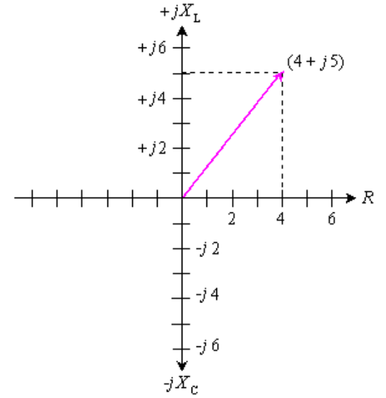
Impedance is commonly written in rectangular form as Z = R + jX, where R is resistance and X is net reactance (positive for inductive, negative for capacitive). On the complex (Argand) plane, resistance lies on the horizontal axis and reactance on the vertical axis: inductive reactance upwards (+j) and capacitive reactance downwards (-j).
Basic formulas
The angular frequency is ω = 2πf, where f is the frequency in hertz. The impedances of basic passive elements are:
- Resistor: ZR = R
- Inductor: ZL = jωL = j2πfL
- Capacitor: ZC = 1/(jωC) = -j/(ωC)
The reactances are:
- Inductive reactance: XL = ωL = 2πfL
- Capacitance reactance (magnitude): XC = 1/(ωC) = 1/(2πfC)
Series and parallel combination rules
For series connections the impedances add algebraically (complex addition):
- Zseries = Z1 + Z2 + ...
For parallel connections the admittances (reciprocals of impedances) add:
- Y = 1/Z and Yparallel = Y1 + Y2 + ...
- After summing admittances, convert back to impedance by Z = 1/Y.
Worked numerical example (preserved values)
Consider a resistor of 100.00 Ω connected in series with an inductor of 10.000 μH at a frequency of 4.0000 MHz. Compute the complex impedance.
Calculate angular frequency and inductive reactance:
ω = 2πf
ω = 2π × 4.0000×106 rad s-1
XL = ωL
XL = 2π × 4.0000×106 × 10.000×10-6
XL = 251.33 Ω
Therefore the series impedance is:
ZRL = R + jXL = 100.00 + j251.33 Ω
Now replace the inductor by a capacitor of 0.0010000 μF (which equals 1.0000 nF) at the same frequency and compute the capacitive reactance:
XC = 1/(2πfC)
XC = 1/(2π × 4.0000×106 × 1.0000×10-9)
XC = 39.789 Ω
Therefore the resistor and capacitor in series have impedance:
ZRC = R - jXC = 100.00 - j39.789 Ω
If the resistor, inductor (10.000 μH) and capacitor (0.0010000 μF) are all connected in series, the reactances algebraically add:
Xnet = XL - XC
Xnet = 251.33 - 39.789
Xnet = 211.54 Ω
Hence
ZRLC = 100.00 + j211.54 Ω
Interpretation: this is equivalent to a 100 Ω resistor in series with an inductive reactance of j211.54 Ω. The inductance that would present 211.54 Ω at 4.0000 MHz is found by inverting XL = 2πfL:
L = XL / (2πf)
L = 211.54 / (2π × 4.0000×106)
L ≈ 8.415 μH
Magnitude and phase of impedance
The magnitude and phase of a complex impedance Z = R + jX are given by:
- |Z| = √(R² + X²)
- θ = arctan(X / R) (phase angle, positive if net reactance is inductive)
Using the example Z = 100.00 + j211.54 Ω:
|Z| = √(100.00² + 211.54²)
|Z| = √(10000 + 44760.0)
|Z| ≈ 234.0 Ω
θ = arctan(211.54 / 100.00)
θ ≈ 64.0°
Admittance and susceptance (brief)
Admittance is the reciprocal of impedance and is useful in analysing parallel networks. It is written as Y = G + jB, where G is conductance (real part) and B is susceptance (imaginary part). For basic elements:
- Resistor: YR = 1/R = G
- Inductor: YL = 1/(jωL) = -j/(ωL)
- Capacitor: YC = jωC
For elements in parallel, add their admittances: Ytotal = ΣY, then Ztotal = 1/Ytotal.
Practical notes and applications
- Matching impedances in transmission lines and radio-frequency circuits is critical to maximise power transfer and minimise reflections.
- Reactive elements (inductors and capacitors) cause phase shifts between voltage and current; designing filters, tuners and resonant circuits relies on controlling impedance versus frequency.
- In power systems, impedance determines short-circuit currents and voltage drops; in measurements, impedance bridges and network analysers characterise components.
Summary
Impedance combines resistance and reactance into a single complex quantity Z = R + jX. Resistance dissipates energy, while reactance stores and releases energy. Use Z = R for resistors, Z = jωL for inductors and Z = 1/(jωC) for capacitors. Series impedances add; parallel impedances combine via admittances. Magnitude and phase of impedance give the total opposition and the phase shift between voltage and current, both essential for circuit analysis and design.


 | Explore Courses for Electrical Engineering (EE) exam |
 | Get EduRev Notes directly in your Google search |