Admittance | Network Theory (Electric Circuits) - Electrical Engineering (EE) PDF Download
Conductivity is the fundamental property of the materials to allow the flow of current through them. Based on the conductive property of the materials they are classified as Conductors, semiconductors, and insulators. Conductors are the materials that allow easy flow of current. Insulators are the materials that oppose the flow of current hence no current passes through them. The amount of current flow a conductor allows depends on the conductivity of the material. Thus, how easily a conducting device can allow the flow of current is measured using the quantity called “Admittance”.
What is Admittance?
- Admittance is the measurement quantity that tells us how easily a conducting device can allow the flow of current through it. The resistance of the circuit is defined as the property of the circuit by which it opposes the flow of current. Resistance only has magnitude and no phase. When dealing with AC circuits sinusoidal signals are used. So, instead of resistance, impedance is used to measure the resistance in AC circuits. Impedance is similar to resistance but unlike resistance, it has both magnitude and phase.
- The real part of the impedance equation gives the resistance value of the circuit. The imaginary part impedance equation represents the reactance part of the circuit. Admittance can be defined as a reciprocal of impedance. Admittance measures the flow of current allowed by the circuit which is inverse of impedance function.
- Besides the conductance of the material, the Admittance value also depends on the Susceptance of the circuit. Susceptance of a material is defined as the ease with which it allows the change in the current flowing through it. It is denoted by the letter – B. Susceptance is the inverse of reactance.
Units
- Admittance is derived by a combination of both conductance and susceptance of the material. Conductance in an AC circuit is denoted as ‘G’ and its units are ‘mho’. Susceptance is the imaginary part of the admittance and is denoted by the symbol ‘B’. Units of susceptance are similar to units of conductance ‘mho’. In modern days, the proper unit of measurement ‘Siemens’ is used instead of ‘mho’. Capacitive susceptance is a negative value, whereas Inductive susceptance is a positive value.
- In an AC circuit, admittance is denoted by the symbol ‘Y’. The units for admittance are ‘Siemens’ similar to the units of conductance. The word ‘Admittance’ was first used by the English engineer, physicist, and mathematician Oliver Heaviside in 1887.
Formula
- Admittance is a complex number. It has both a Real part and the Imaginary Part. Conductance ‘G’ forms the real part of the equation whereas Susceptance ‘B’ forms the imaginary part of the Admittance. Thus the formula of the Admittance ‘Y’ is
- Y = G + jB
Here, Y is the admittance in siemens, G is conductance in siemens and B is Susceptance in siemens. - Conductance is the inverse of resistance, so, G for AC circuits can be written as G = R/(R2 + X2). Here, R denotes the resistance of the AC circuit, and X denotes the reactance of the AC circuit. Similarly for AC circuits susceptance can be calculated from resistance and reactance values as
B = -X/(R2 + X2), it is negative for capacitor susceptance and positive for inductor susceptance.
Derivation of Admittance from Impedance
- Impedance ‘Z’ is calculated using resistance and reactance values of an AC circuit. Impedance is a complex number. The resistance ‘R’ of the circuit forms the real part of the impedance equation. The reactance ‘X’ forms the imaginary part of the impedance equation.
- The formula for impedance is, Z = R +jX.
- Admittance of an AC circuit is the reciprocal of its impedance. Using the impedance value one can easily derive the Admittance values of the circuit.
- Admittance ‘Y’ can be measured as Y = 1/Z
- where ‘Z’ is the impedance, Z = R + jX. So, admittance ‘Y’ can be written as, Y = 1/R+jX.
- Thus, the formula of Admittance when derived from Impedance is, Y = (R -jX/(R2 + X2)).
- ∠Y = arctan(-X/R) = arctan(B/G)
Admittance Triangle
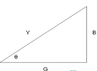
- To better understand the phase and magnitude of admittance and to measure various other related quantities, the Admittance triangle was used. It is formed with conductance ‘G’ at the X-axis, Susceptance ‘B’ at the Y-axis, and Admittance ‘Y’ forming an angle Φ with Conductance at X-axis.
- The figure below shows the Admittance triangle.
 Admittance Triangle
 - From the triangle,
tan Φ = B/G
cos Φ = G/Y, this is the measure of power factor
I = V × Y, where I denotes the Resultant current.
Admittance in Series Circuit
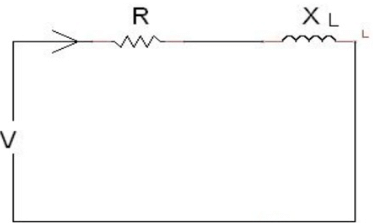
The figure below shows an AC circuit with resistance and Inductive reactance in series. Admittance For Series Circuit
Here R = resistance, XL =inductive reactance.
Y = 1/Z
= 1/R+jXL
= (R -jXL)/(R2 + X2L)
= R/ (R2 + X2L) -jXL/(R2 + X2L)
We know that conductance ‘G’ in an AC circuit can be written as R/ (R2 + X2L) and susceptance ‘B’ can be written as XL/(R2 + X2L).
Thus Y = R/ (R2 + X2L) -jXL/(R2 + X2L) can be written as Y = G -jBL. Here BL is the susceptance of the Inductive circuit.
Similarly for a circuit containing resistance and conductive reactance in series admittance can be derived. Here, XC denotes the conductive reactance of the circuit.
Hence, ‘Y’ can be written as Y = R/ (R2 + X2C)+jXC/(R2 + X2C)
Thus, Y = G +jBC, where BC is the Susceptance of the conductor circuit. The conductive susceptance is a negative value whereas Inductive susceptance is a positive value.
Parallel Circuit
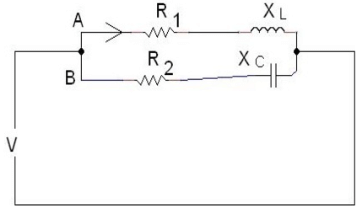
The figure below shows a parallel circuit with two branches A and B. Admittance For Parallel Circuit
- Branch ‘A’ consists of an inductor with inductive reactance XL connected in series with a resistor with resistance ‘R1‘. Branch ‘A’ is connected in parallel with branch ‘B’. Branch ‘B’ consists of a Capacitor with capacitive reactance XC in series with a resistor with resistance ‘ R2‘.
- Voltage V is applied to the circuit. For branch ‘A’, conductance ‘G’ is calculated as,
G1 = R1/R12 + X2L
= R1/Z12, here Z1 is impedance
Susceptance in branch ‘A’ is calculated as BL = XL /R12 + X2L
.i.e. BL = XL /Z12
Thus, ‘Y1‘ = G1 -j BL
= R1/Z12 – j XL /Z12 - Similarly for branch ‘B’, Conductance ‘G2‘ =R2/Z22, where R2 is the resistance of branch ‘B’ and Z2 is the impedance for branch ‘B’. The conductive susceptance’ BC ‘ for branch ‘B’ is calculated as BC = XC /Z22, where ‘ XC ‘ is the conductive reactance of the branch conductor. Thus the admittance ‘Y2‘ of branch ‘B’ is given as ‘Y2‘ = G2 +jBC
- Thus, the total Admittance of the parallel circuit can be calculated as the phasor sum of admittance of each branch. Thus, total admittance Y = Y1 + Y2
= √( R1/Z12 +R2/Z22)2 +( XL /Z12 -XC /Z22)2 - During the designing of the transformers and transmission lines, shunt components play an important role. Shunt components provide the path of least resistance for the flow of current in transmission lines and transformers. These shunt components are specified in terms of their Admittance values. These shunt components are present on each side of the transformer. During simplified transformer analysis, the admittance of shunt components can be neglected. What forms the imaginary part of the admittance equation?
|
73 videos|139 docs|62 tests
|


