Electrodynamometer Type Instruments | GATE Notes & Videos for Electrical Engineering - Electrical Engineering (EE) PDF Download

Introduction
- The electrodynamometer is a transfer-type instrument. A transfer-type instrument is one that may be calibrated with a dc source and then used without modification to measure AC. This requires the transfer type instruments to have the same accuracy for both DC and AC.
These instruments are also called Electrodynamic or Dynamometer Type Instruments. - An electrodynamic instrument is a moving-coil instrument in which the operating field is produced, not by a permanent magnet but by another fixed coil. This instrument can be used either as an ammeter or a voltmeter but is generally used as a wattmeter.
- The electrodynamic or dynamometer-type instrument is a moving-coil instrument but the magnetic field, in which the coil moves, is provided by two fixed coils rather than by permanent magnets (eg: PMMC instruments).
- The schematic diagram of the electrodynamic instrument and a practical meter is shown.
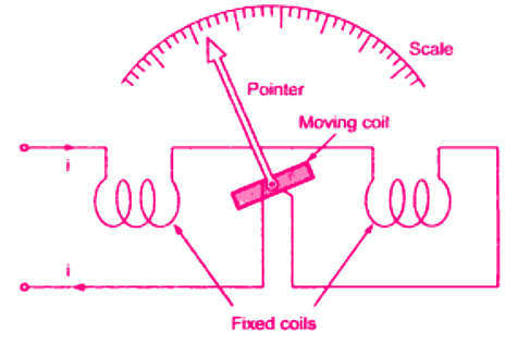 Electrodynamometer or Electrodynamic instrument
 - It consists of two fixed coils, which are symmetrically situated. It would have torque in one direction during one half of the cycle and an equal effect in the opposite direction during the other half of the cycle.
- If, however, we were to reverse the direction of the flux each time the current through the movable coil reverses, a unidirectional torque would be produced for both positive half and negative half of the cycle. In electrodynamic instruments, the field can be made to reverse simultaneously with the current in the movable coil if the fixed coil is connected in series with the movable coil.
Controlling Torque
The controlling torque is provided by two control springs. These springs act as leads to the moving coil.
Damping
Air-friction damping is employed for these instruments and is provided by a pair of aluminium vanes, attached to the spindle at the bottom. These vanes move in a sector-shaped chamber.
Working Principle of Electrodynamometer Instruments
- We can have an idea of the working principle of the electrodynamometer instrument by taking up a permanent magnet moving coil instrument and considering how it would behave on AC.
- It would have torque in one direction during one half of the cycle and an equal effect in the opposite direction during the other half of the cycle.
- If the frequency were very low, the pointer would swing back and forth around the zero point. However, for an ordinary meter, the inertia is so great that on power frequencies the pointer does not go very far in either direction but merely stays (vibrates slightly) around zero.
- If, however, we were to reverse the direction of the field flux each time the current through the movable coil reverses, the torque would be produced in the same direction for both halves of the cycle.
- The field can be made to reverse simultaneously with the current in the movable coil if the field coil is connected in series with the movable coil.
Why PMMC Instruments cannot be used for AC Measurements?
- Now let’s discuss why PMMC Instruments cannot be used for AC Measurements.
- The PMMC instrument cannot be used on AC currents or voltages. If AC supply is given to these instruments, an alternating torque will be developed. Due to the moment of inertia of the moving system, the pointer will not follow the rapidly changing alternating torque and will fail to show any reading.
- In order that the instrument should be able to read AC quantities, the magnetic field in the air gap must change along with the change in current. This principle is used in the electrodynamometer type instrument.
- Instead of a permanent magnet, the electrodynamometer type instrument uses the current under measurement to produce the necessary field flux.
Construction of Electrodynamometer Instruments
In this section, you will how the following parts of an Electrodynamometer Instruments are made.
- Fixed Coil
- Moving Coil
- Control
- Moving System
- Damping
- Shielding
- Cases and Scales
1. Fixed Coils
- The field is produced by a fixed coil. This coil is divided into two sections to give a more uniform field near the center and to allow passage of the instrument shaft.
The instrument as shown in the figure by a milliammeter, or may become a voltmeter by the addition of series resistance. The fixed coils are wound with fine wire for such applications. - Field (fixed) coils are usually wound with a heavy wire carrying the main current in ammeters and watt-meters.
- The wire is stranded where necessary to reduce eddy current losses in conductors. The coils are usually varnished and baked to form a solid assembly.
- These are then clamped in place against the coil supports, This makes the construction rigid so that there is no shifting or change in dimensions which might affect the calibration. The mounting supports are preferably made out of ceramic, as metal parts would weaken the field of the fixed coil on account of eddy currents.
2. Moving Coil
- A single element instrument has one moving coil. The moving coil is wound either as a self-sustaining coil or else on a non-metallic former.
- A metallic former cannot be used as eddy currents would be induced in it by the alternating field. Light but rigid construction is used for the moving coil. It should be noted that both fixed and moving coils are air-cored.
3. Control
- The controlling torque is provided by two control springs. These springs act as leads to the moving coil.
4. Moving System
- The moving coil is mounted on an aluminium spindle. The moving system also carries the counterweights and truss type pointer. Sometimes a suspension may be used in case high sensitivity is desired.
5. Damping
- Air friction damping is employed for these instruments and is provided by a pair of aluminium vanes, attached to the spindle at the bottom. These vanes move in sector-shaped chambers.
6. Shielding
- The field produced by the fixed coils is somewhat weaker than in other types of instruments. It is nearly 0.005 to 0.006 Wb/m2.
- In DC measurements, even the earth’s magnetic field may affect the readings. Thus it is necessary to shield an electrodynamometer type instrument from the effect of stray magnetic fields, Air cored electrodynamometer type instruments are protected against external magnetic fields by enclosing them in a casing of high permeability alloy.
7. Cases and Scales
- Laboratory standard instruments are usually contained in highly polished wooden cases. These cases are so constructed as to remain dimensionally stable over long periods of time.
- The glass is coated with some. conducting material to completely remove the electrostatic effects. The case is supported by arable levelling screws. A spirit level is also provided to ensure proper levelling.
Torque Equation of Electrodynamometer-type Instruments
Let,
i1 = instantaneous value of current in the fixed coils, (A)
i2 = instantaneous value of current in the moving coils, (A)
L1 = self-inductance of fixed coils, (H)
L2 = self-inductance of moving coil, (H)
M = mutual inductance between fixed and moving coils (H)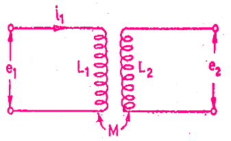 Flux linkage of Coil 1, ψ1 = L1 i1 + Mi2
Flux linkage of Coil 2, ψ2 = L2 i2 + Mi1
Electrical input energy = e1 i1 dt + e2 i2 dt = i1 dψ1 + i2 dψ2
As e1 = dψ1/dt and e1 = dψ2/dt
Electrical input energy = i1 d(L1 i1 + Mi2)+ i2 d(L2 i2 + Mi1)
Energy stored in the magnetic field = ½ i12L1 + ½ i22L2 + i1 i2M
Change in energy stored = d(½ i12L1 + ½ i22L2 + i1 i2M)
From the principle of conservation of energy,
Total electrical input energy = Change in energy in energy stored + mechanical energy
The mechanical energy can be obtained by subtracting above equations
Therefore, mechanical energy =½ i12dL1 + ½ i22dL2 + i1 i2dM
Now, the self-inductances L1 and L2 are constants and, therefore, dL1 and dL2 both are equal to zero.
Hence, mechanical energy = i1 i2 dM
Suppose Ti is the instantaneous deflecting torque and dθ is the change in deflection, then,
Mechanical energy = work done = Ti dθ
Thus we have,
Ti dθ = i1 i2dM
Ti = i1 i2 (dM/dθ)
1. Operation with DC
Let, I1 = current in the fixed coils, I2 = current in the moving coil
So deflecting torque Td = I1 I2 (dM/dθ)
This shows that the deflecting torque depends in general on the product of current I1 and I2 and the rate of change of mutual inductance.
This deflecting torque deflects the moving coil to such a position where the controlling torque of the spring is equal to the deflecting torque. Suppose θ be the final steady deflection.
Therefore controlling torque Tc = kθ where k = spring constant (N-m/rad)
At final steady position Td = Tc
I1 I2 (dM/dθ) = kθ
Deflection, θ = (I1 I2/k)(dM/dθ)
If the two coils are connected in series for measurement of current, the two currents I1 and I2 are equal.
Say, I1 = I2 = I
Thus, deflection of the pointer is θ = (I2/k)(dM/dθ)
For DC use, the deflection is thus proportional to the square of the current and hence the scale non-uniform and crowded at the ends.
2. Operation with AC
Let, i1 and i2 be the instantaneous values of the current carried by the coils. Therefore, the instantaneous deflecting torque is:
Ti = i1 i2 (dM/dθ)
If the two coils are connected in series for measurement of current, the two instantaneous currents i1 and i2 are equal.
Say, i1 = i2 = i
Thus, instantaneous torque on the pointer is Ti = i2 (dM/dθ)
Thus, for ac use, the instantaneous torque is proportional to the square of the instantaneous current. As the quantity i2 is always positive, the current varies and the instantaneous torque also varies. But the moving system due to its inertia cannot follow such rapid variations in the instantaneous torque and responds only to the average torque.
The average deflecting torque over a complete cycle is given by: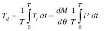
where T is the time period for one complete cycle.
At final steady position Td = TC
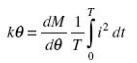
Thus, deflection of the pointer is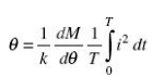
Deflection is thus a function of the mean of the square of the current.
If the pointer scale is calibrated in terms of the square root of this value, i.e. square root of the mean of the square of current value, then RMS value of the AC quantity can be directly measured by this instrument.
3. Sinusoidal Current
If currents i1 and i2 are sinusoidal and are displaced by a phase angle j, i.e.
i1 = im1 sin ωt and i2 = Im1 sin(wt – j)
The average deflecting torque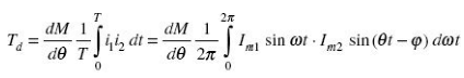
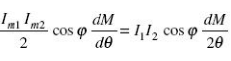
where I1 and I2 are the RMS values of the currents flowing through the coils.
At equilibrium, Td = Tc
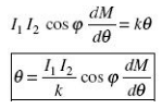
As was in the case with ac measurement, with sinusoidal current also the deflection is a function of the mean of the square of the current.
If the pointer scale is calibrated in terms of the square root of this value, i.e. square root of the mean of the square of current value, then the RMS value of the ac quantity can be directly measured by this instrument.
Types of Electrodynameter Instrument
In this section, you will learn three types of electrodynamometer instruments.
- Electrodynamic Ammeter
- Electrodynamic Voltmeter
- Electrodynamic Wattmeter
1. Electrodynamic Ammeter
In an electrodynamic ammeter, the fixed and moving coils are connected in series as shown in the figure. A shunt is connected across the moving coil for limiting the current.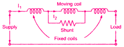 Electrodynamometer ammeter
The reactance–resistance ratio of the shunt and the moving coil is kept nearly the same for the independence of the meter reading with the supply frequency.
Since the coil currents are the same, the deflecting torque is proportional to the mean square value of the current. Thus, the scale is calibrated to read the RMS value.
2. Electrodynamic Voltmeter
The electrodynamic instrument can be used as a voltmeter by connecting a large noninductive resistance (R) of low-temperature coefficient in series with the instrument coil.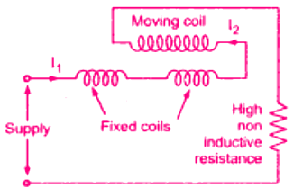 Electrodynamometer voltmeter
3. Electrodynamic Wattmeter
The electrodynamic wattmeter consists of two fixed coils ‘a’ and ‘b’ placed symmetrical to each other and producing a uniform magnetic field. They are connected in series with the load and are called the Current Coils (CC).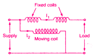 Electrodynamometer wattmeter
The two fixed coils can be connected in series or parallel to give two different current ratings. The current coils carry the full-load current or a fraction of full load current. Thus the current in the current coils is proportional to the load current.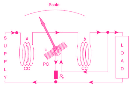 Basic Arrangement of an Electrodynamometer Wattmeter
The moving coil ‘c’, in series with a high non-inductive resistance Rv is connected across the supply. Thus the current flowing in the moving coil is proportional to, and practically in phase with the supply voltage. The moving coil is also called the voltage coil or Pressure Coil (PC).
The voltage coil is carried on a pivoted spindle which carries the pointer, the pointer moved over a calibrated scale.
Two hairsprings are used for providing the controlling torque and for leading current into and out of the moving coil. Damping is provided by air friction.
4. Torque Equation
Let’s derive the torque equation of an electrodynamometer instrument.
Let, if = current in the fixed coil
im = current in the moving coil
i = load current
v = load voltage
Tin = instantaneous value of the deflecting torque
p = instantaneous power
Tin α if im
Since if α i and im α v
Tin α vi α p
Thus, the instantaneous value of the deflecting torque is proportional to the instantaneous power. Owing to the inertia of the moving system, the pointer reads the average power.
In dc circuits, the power is given by the product of voltage and current, and hence the torque is directly proportional to the power. Thus, the instrument indicates the power.
For AC, the instrument indicates the average power. This can be proved as follows:
Tin α vi
Average deflecting torque × average power
Let, v = V, sin d
I = I m sin (θ – Ф)
Average deflecting torque α average value of Vm sin d × I m sin (θ – Ф) α VI cos θ
If Td be the average torque, then
Td α VI cos θ α true power = kP
where P is the true power and k is the constant.
For spring control Tc = ks θ1
where Tc is the control torque, ks is the spring constant and θ1 is the angle of deflection of the pointer.
For steady deflection,
Tc = Td
ks θ1 = kP
θ1 = (k/ks)P
θ1 α P
Hence, in the case of ac also the deflection is proportional to the true power in the circuit. The scale of the electrodynamometer wattmeter is therefore uniform.
Advantages of Electrodynamometer-type Instruments
The advantages of electrodynamometer type instruments are
- They can be used on ac as well as dc measurements.
- These instruments are free from eddy current and hysteresis errors.
- Electrodynamometer-type instruments are very useful for accurate measurement of RMS values of voltages irrespective of waveforms.
- Because of precision grade accuracy and the same calibration for ac and dc measurements, these instruments are useful as transfer type and calibration instruments.
Disadvantages of Electrodynamometer-type Instruments
The advantages of electrodynamometer type instruments are
- As the instrument has a square-law response, the scale is non-uniform.
- These instruments have a small torque/weight ratio, so the frictional error is considerable.
- More costly than Permanent magnet moving coil (PMMC) and Moving Iron (MI) type of instruments.
- Adequate screening of the movements against stray magnetic fields is essential.
- Power consumption is comparably high because of its construction.
Errors in Electrodynamometer Instruments
The various errors in electrodynamometer instruments are,
- Torque to weight ratio
- Frequency errors
- Eddy current errors
- Stray magnetic field error
- Temperature error
1. Torque to weight ratio
- To have reasonable deflecting torque, m.m.f. of the moving coil must be large enough. Thus mmf = NI hence current through moving coil should be high or the number of turns should be large.
- The current can not be made very high because it may cause excessive healing of springs. A large number of turns hence is the only option but it increases the weight of the coil.
- This makes the system heavy reducing torque to weight ratio. This can cause frictional errors in the reading.
2. Frequency errors
- The changes in the frequency cause to change self inductances of moving coil and fixed coil. This causes the error in the reading. The frequency error can be reduced by having equal time constants for both fixed and moving coil circuits.
3. Eddy current errors
- In metal parts of the instrument, the eddy currents get produced. The eddy currents interact with the instrument current, to cause a change in the deflecting torque, to cause the error.
- Hence metal parts should be kept as minimum as possible. Also, the resistivity of the metal parts used must be high, to reduce the eddy currents.
4. Stray magnetic field error
- Similar to moving iron instruments the operating field in the electrodynamometer instrument is very weak.
- Hence the external magnetic field can interact with the operating field to cause a change in the deflection, causing the error. To reduce the effect of the stray magnetic field, the shields must be used for the instruments.
5. Temperature error
- The temperature errors are caused due to the self-heating of the coil, which causes a change in the resistance of the coil. Thus temperature compensating resistors can be used in the precise instrument to eliminate the temperature errors.
Range of Electrodynamometer Instruments
The range of electrodynamometer ammeter and voltmeter are given below.
Ammeter Range
- For fixed coil and moving coil in series – 200 mA
- Moving coil shunted – 30 A
Voltmeter Range – up to 750 V
Comparison of Various Types of Instruments
The comparison of PMMC, moving iron and electrodynamometer type instruments is summarized in the Table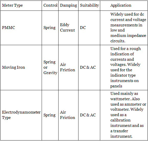
|
27 videos|333 docs
|


Electrodynamometer Type Instruments | GATE Notes & Videos for Electrical Engineering - Electrical Engineering (EE)
,Sample Paper
,Important questions
,Summary
,mock tests for examination
,practice quizzes
,Electrodynamometer Type Instruments | GATE Notes & Videos for Electrical Engineering - Electrical Engineering (EE)
,video lectures
,Extra Questions
,ppt
,Previous Year Questions with Solutions
,shortcuts and tricks
,study material
,MCQs
,past year papers
,Viva Questions
,Electrodynamometer Type Instruments | GATE Notes & Videos for Electrical Engineering - Electrical Engineering (EE)
,Objective type Questions
,Free
,Exam
,Semester Notes
;


Electrodynamometer Type Instruments Free PDF Download
Importance of Electrodynamometer Type Instruments
Electrodynamometer Type Instruments Notes
Electrodynamometer Type Instruments Electrical Engineering (EE) Questions
Study Electrodynamometer Type Instruments on the App
|
© EduRev
|
Education Revolution
|


|


