Data Path, ALU & Control Unit | Digital Circuits - Electronics and Communication Engineering (ECE) PDF Download
Data path
Suppose any data processing operation should be performed in the CPU like transferring the content of register from one place to another, from one register to another register, performing the addition of two numbers in ALU, copying something in memory and copying to register. So, any data processing operation happens in the CPU, then for that data operation, data follows a specific path, which is called "data path.”
Data path is the collection of functional units such as arithmetic logic units or multipliers. Data path is required to perform data processing operations.
To perform any operation in the CPU, data follows a specific path within the CPU to execute the instruction. That followed path is known as a data path.
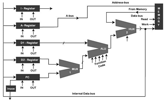
This data path diagram tells how data follows a specific path. It's not a standard diagram as every CPU can have a different data path diagram. Components in the diagram:-

Registers- Here, we have five registers used to store in-out signal data named as instruction register (IR), a program counter (PC), data(D) register, Address(A)-register. Registers are like gates here through which signals are further sent to components to do the micro-operation. Registers are controlled, and signals of registers are directed by the control- unit.
Instruction Register- IR works on IN-OUT signal value. It carries the value of micro-operation which is going to be performed by the CPU.
Data register- In the diagram, we have two data registers named D1 and D2, which save the input data used to perform the micro-operation. D1 data directly goes to ALU, and D2 data moves to MUX 1.
Program Counter- It can take two signals in-out signal. Value of PC sent to MUX forwarded to ALU. The program counter has its incrementer through which the PC's value is incremented in the same register, and it requires a signal named INC. If INC is enabled having value 1, it increases the program counter value and disables having value 0.
Multiplexer- multiplexer is a combinational circuit that takes multiple signals and sends them further as one signal. The diagram shows two multiplexers of 2x1 named MUX 1 and MUX 2, which uses the selected signal to carry the data. It depends on micro-operation. If the select signal is 1, then MUX is enabled, and if the select signal is 0, then MUX is disabled.
Memory- Data is kept in memory with two functions, i.e., the Read and Write function. When the Read function is enabled, data is sent from memory to CPU, and when they write function is enabled, then data is stored in CPU to memory. Read signal enabled than write signal is disabled and vice-versa.
Address bus – Address bus directly carries the input address from the address register to memory.
Data bus- Data bus is used to carry data from memory to registers and registers to memory. Here data bus transfer data from memory to MUX 2.
ALU: Arithmetic Logic Unit
Arithmetic Logic Unit is the full form of ALU. It is present in every CPU to perform operations like addition, subtraction, division, multiplication and many more. It is the main component of the system to apply logic to execute a particular instruction or program. ALU takes two operands as input and function code. ALU can perform multiple functions like subtraction, X-NOR, division and many more. It becomes necessary to provide a function code(assume 10100), which indicates or tells what kind of function ALU has to perform on the given inputs.

Instruction Fetch
Instruction fetch is getting the instruction or reading/fetching an instruction from memory to CPU. Instruction will be fetched from a particular address on which the next instruction is present, and this address is stored in a register called a program counter register. Memory is accessed on an address stored in the program counter, and then on that memory address, instruction is available, and it is kept in the instruction register.
 But this operation cannot be completed in a single step. So to do this complete operation, various steps are required because one component can perform only one operation at one time:-
Firstly, bring the program counter (PC) value into the address register because we cannot bring the value of the program counter to memory. It should be copied to the address register first.
Content of the address register is sent directly to memory, and content can be read from memory. Further, the content of the register is copied to the instruction register. Along with this value of the program in program counter, it is incremented by 1.
Note: Two micro-operation can only perform together only when the operation components are different for both operations.
Control Unit
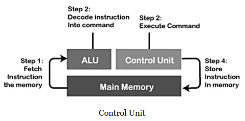
Control unit generates all the signals (in-out) based on which all other component works. The unit generates the signal and sends those signals to components, and components work accordingly. The Control unit is a component present in the CPU which guides the input and signals to reach their required destination (components). It tells computer memory, input/output signal, arithmetic logic unit to respond to the instructions sent to the processor.
Two devices require a control unit:-
- Central Processing Units (CPU’s)
- Graphics Processing Unit(GPU’s)

What is the control Variable?
Control variable- To every signal, we have assigned some names. For example: Read and write signal for memory, I-Register having control signal named IN-OUT, the select signal for multiplexer 1 and 2, out a signal for D1 and D2.
“Control variable is the name of control signal.”
What is the control word?
All the control signals in the process of execution of the program are collected at one place, known as the control word. The control word is collecting all the signals during the fetching of instruction by the components like registers, multiplexer, ALU etc. Control word generates a signal in 0 or 1 form(binary digits), 0 is for disabling, and 1 is for enabling. All the components take these signals meant for them and work accordingly because the different signal is meant for a different component. Components together operate and perform micro-operation.

|
6 videos|76 docs|52 tests
|

|
Explore Courses for Electronics and Communication Engineering (ECE) exam
|

|


