Logic Gates | Digital Circuits - Electronics and Communication Engineering (ECE) PDF Download
Introduction
Logic gates play an important role in circuit design and digital systems. It is a building block of a digital system and an electronic circuit that always have only one output. These gates can have one input or more than one input, but most of the gates have two inputs. On the basis of the relationship between the input and the output, these gates are named as AND gate, OR gate, NOT gate, etc.
There are different types of gates which are as follows:
AND Gate
This gate works in the same way as the logical operator "and". The AND gate is a circuit that performs the AND operation of the inputs. This gate has a minimum of 2 input values and an output value.
Y = A AND B AND C AND D……N
Y = A.B.C.D……N
Y = ABCD……N
Logic Design

Truth Table
OR Gate
This gate works in the same way as the logical operator "or". The OR gate is a circuit which performs the OR operation of the inputs. This gate also has a minimum of 2 input values and an output value.
Y = A OR B OR C OR D……N
Y= A+B+C+D……N
Logic Design

Truth Table

NOT Gate
The NOT gate is also called an inverter. This gate gives the inverse value of the input value as a result. This gate has only one input and one output value.
Y = NOT A
Y = A'
Logic Design

Truth Table
NAND Gate
The NAND gate is the combination of AND gate and NOT gate. This gate gives the same result as a NOT-AND operation. This gate can have two or more than two input values and only one output value.
Y = A NOT AND B NOT AND C NOT AND D……N
Y = A NAND B NAND C NAND D……N
Logic Design
Truth Table
NOR Gate
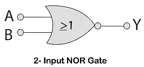
The NOR gate is the combination of an OR gate and NOT gate. This gate gives the same result as the NOT-OR operation. This gate can have two or more than two input values and only one output value.
Y = A NOT OR B NOT OR C NOT OR D……N
Y = A NOR B NOR C NOR D……N
Logic Design

Truth Table

XOR Gate
The XOR gate is also known as the Ex-OR gate. The XOR gate is used in half and full adder and subtractor. The exclusive-OR gate is sometimes called as EX-OR and X-OR gate. This gate can have two or more than two input values and only one output value.
Y = A XOR B XOR C XOR D……N
Y = A⨁B⨁C⨁D……N
Y = AB'+A'B
Logic Design
Truth Table
XNOR Gate
The XNOR gate is also known as the Ex-NOR gate. The XNOR gate is used in half and full adder and subtractor. The exclusive-NOR gate is sometimes called as EX-NOR and X-NOR gate. This gate can have two or more than two input values and only one output value.
Y = A XNOR B XNOR C XNOR D……N
Y = A⊖B⊖C⊖D……N
Y = A'B'+AB
Logic Design
Truth Table

|
6 videos|76 docs|52 tests
|


