ALU & Data Path

Introduction
- Representing and storing numbers were the basic operation of the computers of earlier times. The real go came when computation, manipulating numbers like adding, multiplying came into the picture. These operations are handled by the computer's arithmetic logic unit (ALU). The ALU is the mathematical brain of a computer. The first ALU was INTEL 74181 implemented as a 7400 series is a TTL integrated circuit that was released in 1970.
- The ALU is a digital circuit that provides arithmetic and logic operations. It is the fundamental building block of the central processing unit of a computer. A modern CPU has a very powerful ALU and it is complex in design. In addition to ALU modern CPU contains a control unit and a set of registers. Most of the operations are performed by one or more ALU's, which load data from the input register. Registers are a small amount of storage available to the CPU. These registers can be accessed very fast. The control unit tells ALU what operation to perform on the available data. After calculation/manipulation, the ALU stores the output in an output register.
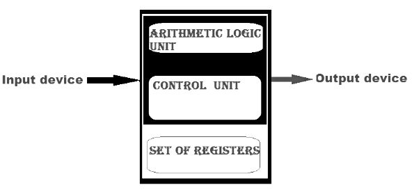 Central Processing
 - The CPU can be divided into two sections: the data section and the control section. The DATA section is also known as the data path.BUS: In early computers "BUS" were parallel electrical wires with multiple hardware connections. Therefore a bus is a communication system that transfers data between components inside a computer, or between computers. It includes hardware components like wires, optical fibers, etc and software, including communication protocols. The Registers, ALU, and the interconnecting BUS are collectively referred to as data paths.
Types of the bus are:
- Address bus: The buses which are used to carry address.
- Data bus: The buses which are used to carry data.
- Control bus: If the bus is carrying control signals.
- Power bus: If it is carrying clock pulse, power signals it is known as a power bus, and so on.
The bus can be dedicated, i.e., it can be used for a single purpose or it can be multiplexed, i.e., it can be used for multiple purposes. When we would have different kinds of buses, different types of bus organizations will take place.
- Program Counter:
A program counter (PC) is a CPU register in the computer processor which has the address of the next instruction to be executed from memory. As each instruction gets fetched, the program counter increases its stored value by 1. It is a digital counter needed for faster execution of tasks as well as for tracking the current execution point. - Instruction Register:
In computing, an instruction register (IR) is the part of a CPU's control unit that holds the instruction currently being executed or decoded. An instruction register is the part of a CPU's control unit that holds the instruction currently being executed or decoded. The instruction register specifically holds the instruction and provides it to the instruction decoder circuit. - Memory Address Register:
The Memory Address Register (MAR) is the CPU register that either stores the memory address from which data will be fetched from the CPU, or the address to which data will be sent and stored. It is a temporary storage component in the CPU(central processing unit) that temporarily stores the address (location) of the data sent by the memory unit until the instruction for the particular data is executed. - Memory Data Register:
The memory data register (MDR) is the register in a computer's processor, or central processing unit, CPU, that stores the data being transferred to and from the immediate access storage. Memory data register (MDR) is also known as memory buffer register (MBR). - General Purpose Register:
General-purpose registers are used to store temporary data within the microprocessor. It is a multipurpose register. They can be used either by a programmer or by a user.
One Bus Organization
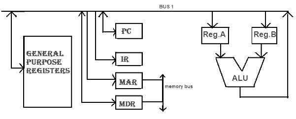 One Bus Organisation
- In one bus organization, a single bus is used for multiple purposes. A set of general-purpose registers, program counters, instruction registers, memory address registers (MAR), memory data registers (MDR) are connected with the single bus. Memory read/write can be done with MAR and MDR. The program counterpoints to the memory location from where the next instruction is to be fetched. Instruction register is that very register will hold the copy of the current instruction. In the case of one bus organization, at a time only one operand can be read from the bus.
- As a result, if the requirement is to read two operands for the operation then the read operation needs to be carried twice. So that's why it is making the process a little longer. One of the advantages of one bus organization is that it is one of the simplest and also this is very cheap to implement. At the same time a disadvantage lies that it has only one bus and this "one bus" is accessed by all general-purpose registers, program counter, instruction register, MAR, MDR making each and every operation sequential. No one recommends this architecture nowadays.
Two Bus Organizations
- To overcome the disadvantage of one bus organization another architecture was developed known as two bus organization. In two bus organizations, there are two buses. The general-purpose register can read/write from both the buses. In this case, two operands can be fetched at the same time because of the two buses. One bus fetch operand for ALU and another bus fetch for register. The situation arises when both buses are busy fetching operands, the output can be stored in a temporary register and when the buses are free, the particular output can be dumped on the buses.
- There are two versions of two bus organizations, i.e., in-bus and out-bus. From in-bus, the general-purpose register can read data and to the out bus, the general-purpose registers can write data. Here buses get dedicated.
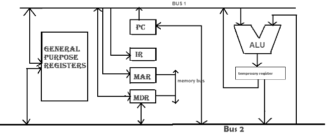 Two Bus Organizations
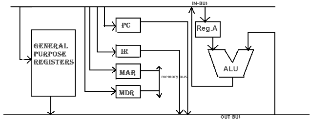 Two Bus Organizations
Three Bus organization
In three bus organizations we have three buses, OUT bus1, OUT bus2, and an IN bus. From the out buses, we can get the operand which can come from the general-purpose register and evaluated in ALU and the output is dropped on In Bus so it can be sent to respective registers. This implementation is a bit complex but faster in nature because in parallel two operands can flow into ALU and out of ALU. It was developed to overcome the "busy waiting" problem of two bus organizations. In this structure after execution, the output can be dropped on the bus without waiting because of the presence of an extra bus. The structure is given below in the figure.
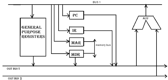 Three Bus Organization
The main advantages of multiple bus organizations over the single bus are as given below.
- Increase in size of the registers.
- Reduction in the number of cycles for execution.
- Increases the speed of execution or we can say faster execution.


 | Explore Courses for Computer Science Engineering (CSE) exam |  |
 | Get EduRev Notes directly in your Google search | |