Single Cycle Datapaths
A single-cycle datapath is a processor design in which each instruction is fetched, decoded, executed, accesses memory (if required) and writes back its result to the register file within one clock cycle. The clock period must be long enough to accommodate the slowest instruction so that every instruction completes within that single cycle.
Key features
- The data memory typically has a single address input port. Whether the memory performs a read or write in a cycle is determined by the control signals MemRead and MemWrite.
- There are separate memories for instructions and data (a Harvard-like organisation) in common single-cycle implementations; this allows one instruction fetch and one data access to be modelled without multiple accesses to the same memory in the same cycle.
- The datapath includes an ALU for arithmetic and logic operations, a program counter (PC), register file, and extra adders for PC-based computations (for example, one adder to compute PC + 4 and another for branch target calculation).
- Control signals are generated once per instruction and remain stable for the whole cycle; the control logic produces signals such as register-write enable, ALU operation, MemRead, MemWrite and others.
- Because every instruction uses the entire datapath resources in the same cycle, hardware sharing is possible but the clock period must accommodate the worst-case path through the datapath.
Advantages and disadvantages
- Advantage: Simple control and easy timing model; CPI (cycles per instruction) is exactly 1.
- Disadvantage: Clock period is long (set by the slowest instruction). As a result the overall processor throughput is low compared to designs that split work across shorter pipeline stages.
Pipeline Datapaths
Pipelining divides the instruction execution process into several stages and overlaps execution of multiple instructions. The aim is to increase instruction throughput by allowing multiple instructions to be at different stages of execution simultaneously.
Typical pipeline stages (5-stage classic design)
- IF (Instruction Fetch): Read instruction from instruction memory and compute next PC (PC + 4).
- ID (Instruction Decode / Register Fetch): Decode the instruction, read registers, sign-extend immediates and generate control signals.
- EX (Execute / Effective Address): Perform ALU operations or compute effective addresses for loads/stores; perform branch target addition and compare for branch decision.
- MEM (Memory Access): Access data memory for loads or stores.
- WB (Write Back): Write results back to the register file.
Pipeline implementation details
- Pipeline registers are inserted between stages (for example, IF/ID, ID/EX, EX/MEM, MEM/WB) to hold the information that flows from one stage to the next.
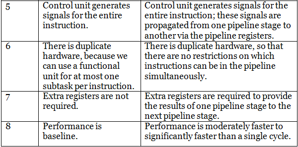
- Because different instructions use different parts of the datapath in the same clock cycle, the processor often needs duplicated or additional hardware (for example, separate adders or additional multiplexers) so that operations required simultaneously do not conflict.
- Control signals are generated in early stages and passed along pipeline registers to later stages where they are needed.
- The pipeline reduces the required clock period because each stage has smaller delay than the entire single-cycle datapath; ideally, a pipelined processor can complete one instruction per cycle after the pipeline fills.
Differences between Single Datapath and Pipeline Datapath
- Execution model: Single-cycle executes one instruction completely per cycle; pipelined executes parts of multiple instructions concurrently (overlapped execution).
- Clock period: Single-cycle clock must accommodate the longest instruction path; pipelined clock period is determined by the longest pipeline stage plus pipeline-register overhead.
- Throughput: Single-cycle throughput is low (one instruction per long cycle). Pipelined throughput is higher because it can finish approximately one instruction per shorter cycle once the pipeline is full.
- Hardware duplication: Pipelined designs often require duplicated hardware resources or additional multiplexing to allow simultaneous use by different instructions; single-cycle may reuse resources within the single cycle.
- Complexity: Single-cycle control is simpler; pipelined control must handle hazards, forwarding, stalls and flushes, making it more complex.
- Performance sensitivity: Pipelined performance is sensitive to hazards (structural, data, control) and branch behaviour; single-cycle is insensitive to these at runtime because no overlapping occurs.


Pipeline Hazards and Their Resolution
Structural hazards
- Occur when two stages require the same hardware resource in the same cycle (for example, a single-ported memory used for instruction fetch and data access simultaneously).
- Mitigation: replicate resources (separate instruction and data memories), or add multiplexing with stall logic.
Data hazards
- Happen when an instruction depends on the result of a preceding instruction that has not yet written its result.
- Common solutions:
- Forwarding (bypassing): Route ALU results directly from a producing stage to a consuming stage before they are written back.
- Stalling (pipeline bubble): Insert one or more cycles of delay when forwarding is insufficient (for example, load-use hazards where a load's data is available only after MEM stage).
- A hazard detection unit detects the need for stalls and controls insertion of pipeline bubbles.
Control hazards (branch hazards)
- Occur when the next instruction to fetch depends on the outcome of a branch or jump.
- Mitigation techniques:
- Flush instructions following a branch if the branch is taken.
- Branch prediction (static or dynamic) to reduce the number of flushes and stalls.
- Delayed branch (architectural compiler-level solution) where the instruction immediately after a branch executes regardless of the branch outcome, if safe.
To compare single-cycle and pipelined designs, consider the clock period and CPI (cycles per instruction). A simple ideal model:
The single-cycle clock period equals the sum of delays of all stages. Put mathematically:
\\[ T_{single} = t_{IF} + t_{ID} + t_{EX} + t_{MEM} + t_{WB} \\]
The pipelined clock period is determined by the slowest pipeline stage plus the pipeline register overhead:
\\[ T_{pipeline} = \max(t_{IF}, t_{ID}, t_{EX}, t_{MEM}, t_{WB}) + t_{reg} \\]
Ideal pipelined CPI (after pipeline fill) is 1, so ideal throughput improvement (speedup) is approximately:
\\[ \text{Speedup} \approx \frac{T_{single}}{T_{pipeline}} \\]
In practice, stalls due to hazards increase the effective CPI. The actual CPI can be modelled as:
\\[ \text{CPI}_{actual} = 1 + \text{average stalls per instruction} \\]
Worked numerical example
Assume stage delays (in arbitrary time units):
- IF = 2
- ID = 2
- EX = 4
- MEM = 3
- WB = 1
- Pipeline register overhead = 0.5
Compute single-cycle clock period and pipelined clock period, then approximate speedup.
Solution steps:
Compute the single-cycle period by summing stage delays.
\\[ T_{single} = 2 + 2 + 4 + 3 + 1 = 12 \\]
Compute the pipeline clock period as the maximum stage delay plus register overhead.
\\[ T_{pipeline} = \max(2,2,4,3,1) + 0.5 = 4 + 0.5 = 4.5 \\]
Compute the ideal speedup.
\\[ \text{Speedup} \approx \frac{12}{4.5} \approx 2.67 \\]
This shows the pipelined processor can be almost 2.67× faster in this idealised case. Real speedup will be lower if stalls due to hazards are frequent.
Instruction Overlap and Timing Diagram (Conceptual)
- In a pipeline, the timeline for instructions overlaps: while instruction 1 is in EX, instruction 2 is in ID and instruction 3 is in IF.
- After pipeline fill, ideally one instruction completes every cycle; the initial fill and final drain add latency but do not affect steady-state throughput significantly for long instruction streams.
- Hazards introduce bubbles or require forwarding paths; control flow changes (branches) may require flushing partially processed instructions.
Design Trade-offs and Practical Considerations
- Decomposing the datapath into stages reduces the critical-path delay, allowing a faster clock, but adds complexity in control and hazard handling.
- Adding pipeline stages further shortens stage delays but increases pipeline-register overhead and the penalty for hazards, so there is an optimal number of stages for a given technology and instruction mix.
- Real processors use a mix of techniques-forwarding, sophisticated branch prediction, out-of-order execution, and speculative execution-to reduce the impact of hazards and improve utilisation of pipeline resources.
Conclusion
Single-cycle datapaths are simple to understand and implement but have poor clock frequency and throughput because the clock must accommodate the slowest instruction. Pipelined datapaths increase throughput by overlapping instruction execution and using shorter clock cycles; they require additional control logic to handle structural, data and control hazards, and their performance gain depends on the frequency of stalls and branch penalties. Understanding both designs is essential for analysing processor performance and for implementing more advanced techniques that further improve instruction throughput.