EMF & Internal Resistance | Physics for Grade 12 PDF Download
| Table of contents |

|
| Introduction |

|
| Calculating E.m.f |

|
| Determining Internal Resistance |

|
| Potential Difference (p.d.) |

|
| Energy Transfer in Circuits |

|
Introduction
- When charge passes through a power supply such as a battery, it gains electrical energy
- The electromotive force (e.m.f) is the amount of chemical energy converted to electrical energy per coulomb of charge (C) when charge passes through a power supply

- E.m.f can be represented by the symbol ε (greek letter epsilon)
- It is not actually a force, and is measured in volts (V)
- The e.m.f source is from a battery or a power supply
- E.m.f is equal to the potential difference across the cell when no current is flowing
- E.m.f can be measured by connecting a high-resistance voltmeter around the terminals of the cell in an open circuit, as so:
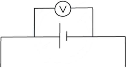
e.m.f is measured using a voltmeter connected in parallel with the cell
Internal Resistance
- All power supplies have some resistance between their terminals
- This is called internal resistance (r)
- It is internal resistance that causes the charge circulating to dissipate some electrical energy from the power supply itself
- This is why the cell becomes warm after a period of time
- Therefore, over time the internal resistance causes loss of voltage or energy loss in a power supply
- A cell can be thought of as a source of e.m.f with an internal resistance connected in series. This is shown in the circuit diagram below:
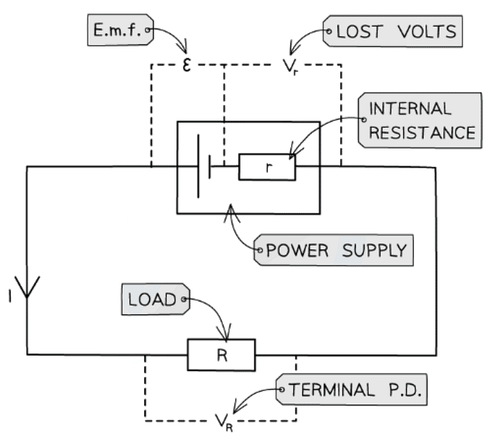
Circuit showing the e.m.f and internal resistance of a power supply
- Where:
- Resistor R is the ‘load resistor’
- r is the internal resistance
- ε is the e.m.f
- Vr is the lost volts
- VR is the p.d across the load resistor, which is the same as the terminal p.d
Terminal p.d & Lost Volts
- The terminal potential difference (p.d) is the potential difference across the terminals of a cell
- If there was no internal resistance, the terminal p.d would be equal to the e.m.f
- It is defined as:
V = IR - Where:
- V = terminal p.d (V)
- I = current (A)
- R = resistance (Ω)
- If a cell has internal resistance, the terminal p.d is always lower than the e.m.f
- If you have a load resistor R across the cell's terminals, then the terminal p.d V also the p.d across the load resistor
- In a closed circuit, current flows through a cell and a potential difference develops across the internal resistance
- Since resistance opposes current, this reduces the energy per unit charge (voltage) available to the rest of the external circuit
- This difference is called the ‘lost volts’
- Lost volts is usually represented by little v
- It is defined as the voltage lost in the cell due to internal resistance, so, from conservation of energy:
- v = e.m.f − terminal p.d
- v = ε – V = Ir (Ohm’s law)
- Where:
- v = lost volts (V)
- I = current (A)
- r = internal resistance of the battery (Ω)
- ε = e.m.f (V)
- V = terminal p.d (V)
- Therefore, lost volts is the difference between the e.m.f and the terminal p.d
Calculating E.m.f
- The e.m.f ε is defined by the equation:

- E.m.f can therefore be defined as the total, or maximum, voltage available to the circuit
Example: A battery of e.m.f 7.3 V and internal resistance r of 0.3 Ω is connected in series with a resistor of resistance 9.5 Ω.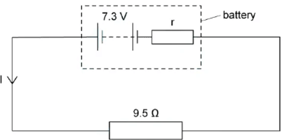
Determine:
(a) The current in the circuit
(b) Lost volts from the battery
(a) Step 1: using the e.m.f equation to determine the current i ε = i (r + r)
Step 2: rearrange for i
i = ε/(r + r)Step 3: substitute in the values
i = 7.3/(9.5 + 0.3) = 0.745... = 0.7 a (2 s.f.)(b) Step 1: The lost volts is the voltage lost due to internal resistance lost volts = i x r
Step 2: substitute in the values lost volts = 0.7 . 0.3 = 0.21 = 0.2v (2 s.f.)
Determining Internal Resistance
Aims of the Experiment
The overall aim of the experiment is to investigate the relationship between e.m.f and internal resistance by measuring the variation of current and voltage using a variable resistor
Variables
- Independent variable = resistance, R (Ω)
- Dependent variable = voltage, V (V) & current, I (A)
- Control variables:
- E.m.f of the cell
- Internal resistance of the cell
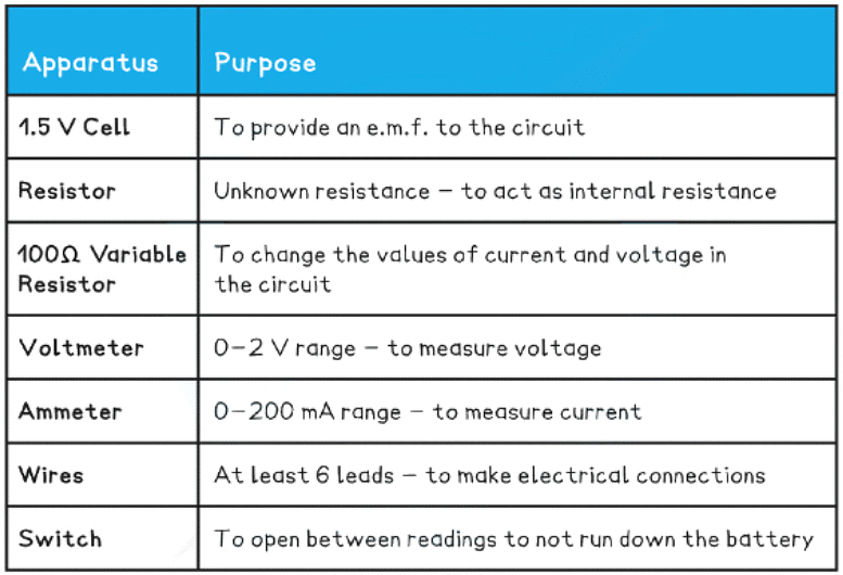
Equipment List
- Resolution of measuring equipment:
- Voltmeter = 1 mV
- Ammeter = 0.1 mA
Method
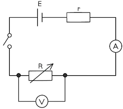
- The cell and the resistor, labelled r, should be connected in series and considered to be a single cell
- With the switch open, record the reading V on the voltmeter
- Set the variable resistor to its maximum value, close the switch and record V and the reading I on the ammeter - make sure to open the switch between readings
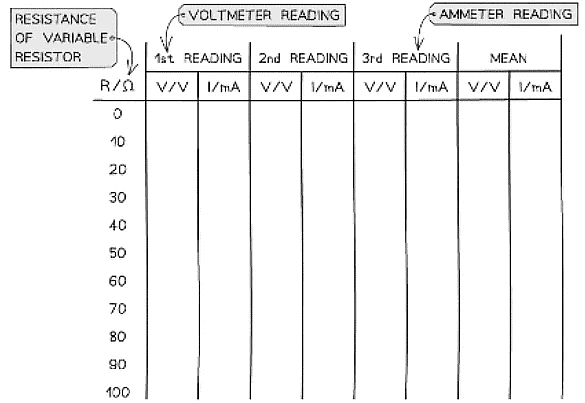
- Vary the resistance of the variable resistor up to a minimum of 8-10 readings and record values for V and I for each resistance. Ensure to take readings for the whole range of the variable resistor
- An example of a suitable table might look like this:
Analysing the Results
- The relationship between e.m.f. and internal resistance is given by
ε = I (R + r) - Where:
- ε = electromotive force (V)
- I = current (A)
- R = resistance of the load in the circuit (Ω)
- r = internal resistance of the cell (Ω)
- This can be simplified into the form:
ε = IR + Ir = V + Ir - Rearranging this equation for V:
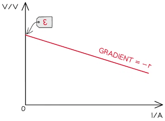
V = –rI + ε - Comparing this to the equation of a straight line: y = mx + c
- y = V (V)
- x = I (A)
- Gradient = –r (Ω)
- Y-intercept = ε (V)
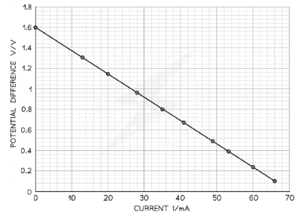
- Plot a graph of V against I and draw a line of best fit
- Measure the gradient of the graph and compare it with the manufacturer’s value of the resistor
- The y-intercept will be the e.m.f and the gradient will be the negative internal resistance:
Evaluating the Experiment
Systematic Errors:
- Only close the switch for as long as it takes to take each pair of readings
- This will prevent the internal resistance of the battery or cell from changing during the experiment
Random Errors:
- Only use fairly new cells otherwise the e.m.f. and internal resistance of run-down batteries can vary during the experiment
- Wait for the reading on the voltmeter and ammeter to stabilise (stop fluctuating) before recording the values
- Take multiple repeat readings (at least 3) for each voltage and current and calculate a mean to reduce random errors
Safety Considerations
- This is a very safe experiment, however, electrical components can get hot when used for a long period
- Switch off the power supply right away if burning is smelled
- Make sure there are no liquids close to the equipment, as this could damage the electrical equipment
Example: In an experiment, a student uses a variable resistor as an external load. The current flowing through the circuit is measured with a suitable milliammeter and the potential difference across the variable resistor is measured with a voltmeter for a range of resistance values. The data collected was as follows: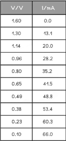
Plot a graph of these results and determine the e.m.f. and the internal resistance directly from the graph.
Step 1: Plot the data on a graph of V against I and draw a line of best fit
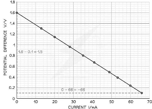
Step 2: Draw the largest triangle possible in order to calculate the gradient
Step 3: Determine the e.m.f. and the internal resistance from the graph
V = –rI + E
- From this equation:
- Gradient = –r (Ω)
- Y-intercept = E (V)
- Therefore:
- Internal resistance, r = 22.7 Ω
- E.m.f. E = 1.60 V
Potential Difference (p.d.)
- A cell makes one end of the circuit positive and the other negative
- This sets up a potential difference (p.d) across the circuit
- The potential difference across a component in a circuit is defined as
- The energy transferred per unit charge flowing from one point to another
- The energy transfer is from electrical energy into other forms
- Potential difference is measured in volts (V). This is the same as a Joule per coulomb (J C-1)
- If a bulb has a voltage of 3 V, every coulomb of charge passing through the bulb will lose 3 J of energy
- The potential difference of a power supply connected in series is always shared between all the components in the circuit
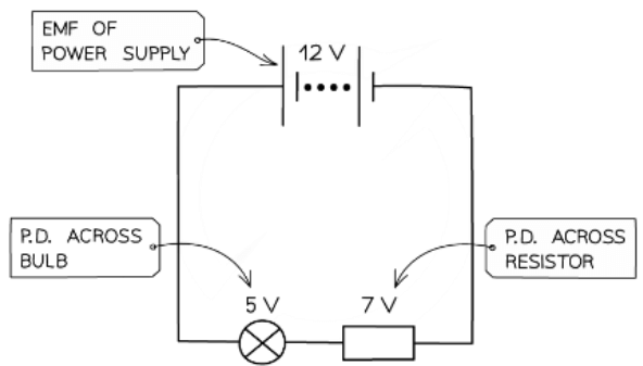
The potential difference is the voltage across each component in a circuit
- Potential difference or voltage is measured using a voltmeter
- A voltmeter is always set up in parallel to the component you are measuring the voltage for
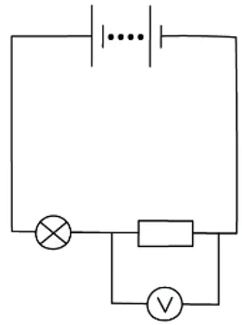
Potential difference can be measured by connecting a voltmeter in parallel between two points in a circuit
E.m.f & Potential Difference
- The difference between potential difference and e.m.f is the type of energy transfer per unit charge

- When charge passes through a resistor, for example, its electrical energy is converted to heat in the resistor
- The resistor, therefore, has a potential difference across it
- Potential difference describes the loss of energy from charges
- Ie. when electrical energy is transferred to other forms of energy in a component
- E.m.f. describes the transfer of energy from the power supply to electrical charges within the circuit
Energy Transfer in Circuits
- The [popover id="3iNVV0LBm5pf25r~" label = "e.m.f"] is defined as the energy transferred by the power supply per unit charge
- This energy transformed is also equal to the work done by the moving charge
- This is defined by the equation:
W = εQ - Where:
- W = work done / energy transferred (J)
- ε = e.m.f (V)
- Q = charge (C)
- The potential difference is the energy transferred to the electrical component per unit charge
- This means the equation can also be written as:
W = VQ - Where:
- V = potential difference (V)
- These equations show that
- 1 V = 1 J C-1
Example: An electric kettle requires 0.4 MJ to be supplied to boil a cup of water. The e.m.f. of the mains supply is 230 V. Calculate the charge supplied.
Step 1: List the known quantities
- Energy transferred (work done), W = 0.4 MJ = 0.4 × 10⁶ J
- E.m.f, ε = 230 V
Step 2: Write the relevant equation
- W = εQ
Step 3: Rearrange for charge, Q
- Q = W ÷ ε
Step 4: Substitute in the values
- Q = (0.4 × 10⁶) ÷ 230 = 1739.13 = 1700 C
Energy Transfer for Charged Particles
- A dynamo or battery transfer energy to each charge carrier, which are electrons in metals, as they pass through
- Each electron has a charge of e
- Since the energy transferred (work done) W is defined as
W = QV - Then:
W = eV - Where the charge Q is now replaced with the charge of the electron e
- 1 eV is 1 electronvolt, which is defined as:
- A unit of energy equal to the work done by an electron accelerated through a potential difference of 1 volt
- When a potential difference is applied across a conductor, the electrons are accelerated and gain kinetic energy
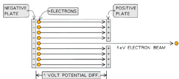
Electron beam accelerated through a potential difference of 1 V
- This kinetic energy gained is equal to an electronvolt:
eV = ½ mv2
Where:
e = elementary charge (C)
V = potential difference (V)
m = mass of the electron (kg)
v = speed of the electrons (m s-1)
- To convert between eV and J:
- eV → J: multiply by 1.6 × 10⁻¹⁹
- J → eV: divide by 1.6 × 10⁻¹⁹
Example: Calculate the speed of an electron that is accelerated through a potential difference of 5 V.
Step 1: List the known quantities
- Charge of an electron, e= 1.6 x 10⁻¹⁹ C (from data sheet)
- Potential difference, V= 5 V
- Electron rest mass, m= 9.11 x 10⁻³¹ kg (from data sheet)
Step 2: Write the relevant equation
- eV = 1/2mv2
Step 3: Rearrange for the speed, v
Step 4: Substitute in the values
|
142 videos|312 docs|132 tests
|

