Race Around Condition


Introduction
The race around condition is a problem that can occur in a J-K flip-flop when both inputs are high (J = K = 1) and the clock (CP) remains at the active level for a relatively long time. Under these conditions the output may toggle repeatedly while the clock is active, producing an unstable or unpredictable output at the end of the clock period. This section explains the cause, the characteristic behaviour of the J-K flip-flop, and common remedies including the master-slave JK flip-flop.
J-K Flip-Flop
A J-K flip-flop is a universal clocked bistable device with two inputs (J and K) and outputs Q and Q′. It combines the features of SR and T flip-flops and removes the forbidden state of the SR latch by using feedback.
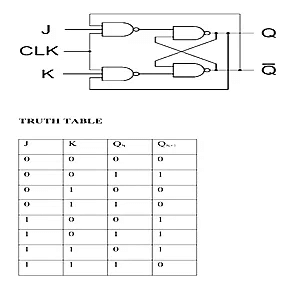
| J | K | Q(t) | Q(t + 1) | Operation |
|---|---|---|---|---|
| 0 | 0 | Q | Q | No change |
| 0 | 1 | Q | 0 | Reset |
| 1 | 0 | Q | 1 | Set |
| 1 | 1 | Q | Q′ | Toggle |
The characteristic equation of the J-K flip-flop is:
Q(t + 1) = J · Q′ + Q · K′
This equation reproduces each row of the truth table: when J = K = 1 the next state is the complement of the present state (toggle).
Race Around Condition in J-K Flip-Flop
- When a J-K flip-flop is level sensitive to the clock (i.e. it responds while the clock remains at the active level) and J = K = 1, the internal feedback can cause the output to change, then feed back and change again within the same clock level. This produces successive toggles while the clock is active.
- This repeated toggling while the clock is active is known as the race around condition. The final output after the clock returns to the inactive level becomes uncertain if more than one toggle has occurred.
- The fundamental cause is the combination of active-level clocking and finite propagation delays in the flip-flop's internal gates; each change of Q appears at the inputs after some delay and may trigger another change before the clock falls.
- One simple mitigation is to make the active clock pulse very short (shorter than the propagation + feedback delay), so the flip-flop cannot complete more than one toggle. This approach is not robust for general synchronous design because it depends on timing margins.
- A reliable solution is to use either a master-slave arrangement or an edge-triggered J-K flip-flop. These designs ensure that only a single state change can occur per clock cycle even when J = K = 1.
Master-Slave J-K Flip-Flop
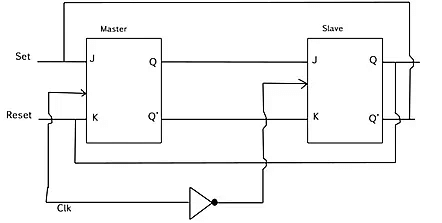
- A master-slave JK flip-flop is formed by connecting two level-sensitive J-K flip-flops in series: the first is the master and the second is the slave.
- The master stage is enabled while the clock is at one level, and the slave stage is enabled while the clock is at the opposite level. An inverter is used to provide complementary clock signals to the two stages so only one stage is transparent at any time.
- The output of the master feeds the inputs of the slave so the slave captures the master's state when the clock switches levels; the slave's output is the final output Q.
- Because the master and slave are never transparent at the same time, the feedback path cannot produce repeated toggling within a single clock cycle; therefore the master-slave arrangement prevents the race around condition.
Working of a Master-Slave Flip-Flop
- When the clock (CP) is at the level that enables the master (for the common configuration the master is enabled on the high level), the master is transparent and follows the inputs J and K; during this time the slave is disabled and its output remains unchanged.
- When the clock returns to the opposite level (the level that disables the master and enables the slave), the master is latched and the slave becomes transparent, copying the latched master state to the final output Q.
- Thus any internal toggling inside the master while it was transparent does not directly change the final output until the transition when the slave is enabled; this arrangement allows only one effective change of the final output per clock cycle.
- For the four input combinations:
- J = 0, K = 0: both master and slave hold their states; final output does not change.
- J = 0, K = 1: master captures reset; after transfer the slave outputs Q = 0.
- J = 1, K = 0: master captures set; after transfer the slave outputs Q = 1.
- J = 1, K = 1: master may toggle while enabled, but only the state latched at the end of the master's active level is transferred to the slave; the final output toggles at most once per clock cycle.
- Because the slave is enabled only after the master has been disabled, the feedback path that produces toggling cannot act on the final output while the clock is at the enabling level for the master; this prevents the race around effect and produces predictable output behaviour.
Other Methods to Overcome Race Around Condition
- Edge-triggered flip-flops: Implement the J-K function in an edge-triggered device; these devices change output only on a clock edge (rising or falling) and therefore avoid repeated toggling during the clock level.
- Pulse-width control: Make the active clock pulse shorter than the minimum time required for a feedback toggle. This is sometimes used in specific hardware but requires tight timing control.
- Use of gating or synchronisation logic: Design the surrounding synchronous circuit so that inputs that can cause toggling are prevented from being simultaneously active during the sampling window, or use additional gating to enforce one-shot behaviour.
Illustrative Example (Conceptual)
Consider a level-sensitive J-K flip-flop with nonzero gate and propagation delays. If the clock pulse remains high long enough for the output change to propagate to the inputs and cause another output change, the flip-flop may toggle several times while the clock is high. In contrast, the master-slave arrangement isolates the final output from these internal toggles and transfers only the master's latched value to the slave once per clock cycle, so the final output toggles at most once.
Summary
The race around condition is caused by level-sensitive operation of a J-K flip-flop when J = K = 1 and the clock remains active long enough for multiple internal toggles. Practical remedies are the use of a master-slave configuration or an edge-triggered design, both of which ensure a single, predictable change of the final output per clock cycle.


 | Explore Courses for Computer Science Engineering (CSE) exam |
 | Get EduRev Notes directly in your Google search |