Counters Counters

Introduction
An N-bit binary counter is a sequential circuit built from N flip-flops that produces a binary sequence of states. If the counter produces the sequence from 0 to 2N - 1 it is called a binary up counter. If it produces the sequence from 2N - 1 down to 0 it is called a binary down counter. Counters are classified by how the clock is applied to their flip-flops:
- Asynchronous counters
- Synchronous counters
Asynchronous Counters
An asynchronous counter (often called a ripple counter) is a counter in which the flip-flops do not receive the same clock signal simultaneously. The system clock is applied only to the least significant stage. The clock input to each subsequent stage is derived from the output of the previous stage. Because each stage changes after the previous stage, outputs change at different times and the transition ripples through the stages.
Key points and practical consequences:
- Ripple effect: state change propagates from LSB to MSB so outputs do not switch simultaneously.
- Propagation delay accumulation: overall response time depends on the sum of stage propagation delays; this limits maximum input clock frequency.
- Simple hardware: easy to implement with minimal gating; T inputs can be held high for T-flip-flop implementations.
- Glitches and timing hazards: intermediate unstable states may occur while the ripple propagates, unsuitable where glitch-free outputs are required at high speed.
Asynchronous Binary Up Counter
An N-bit asynchronous binary up counter uses N T flip-flops with their T inputs held at logic 1. The counter advances by 1 (in binary) on each active (here negative) edge of the external clock applied to the LSB stage. Each higher stage uses the output of the previous stage as its clock, so it toggles when the previous stage makes the appropriate transition.
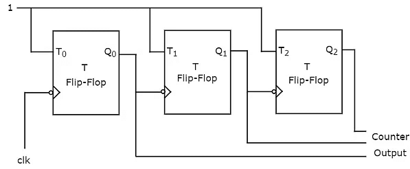
The typical 3-bit implementation has three T flip-flops, all negative-edge triggered, with T = 1 at every stage. Operation of the 3-bit counter (Q2 Q1 Q0, MSB → LSB) can be understood from its count sequence and transition conditions.
Behaviour explanation:
- Q0 toggles on every negative edge of the external clock.
- Q1 toggles on the negative edge of Q0 (i.e. when Q0 goes from 1 to 0).
- Q2 toggles on the negative edge of Q1 (i.e. when Q1 goes from 1 to 0).
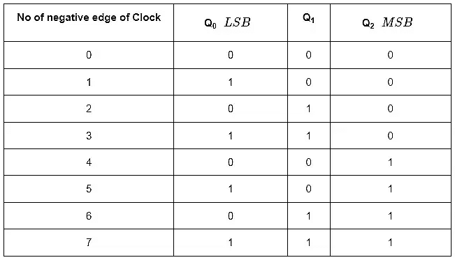
Starting from 000, successive negative clock edges produce the sequence 000 → 001 → 010 → 011 → 100 → 101 → 110 → 111, and on the next negative edge the sequence returns to 000. The counter therefore cycles through 23 = 8 distinct states.
Timing note: the time between the external clock edge and the final stable state at the MSB includes the propagation delays of each stage; this cumulative delay is why asynchronous counters cannot be clocked as fast as synchronous designs.
Asynchronous Binary Down Counter
An N-bit asynchronous binary down counter is similar in structure to the up counter, but each stage (except the LSB) receives the complemented output of the previous stage as its clock input. Effectively, a stage toggles when the previous stage changes from 0 to 1, producing a descending binary sequence on successive clock events.
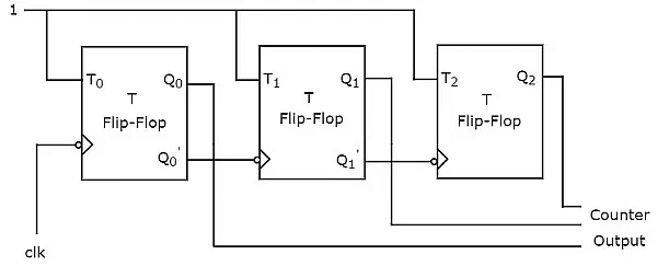
For a 3-bit asynchronous down counter the arrangement is identical except the clock to stage i+1 is taken from Qi′ rather than Qi. This ensures that higher-order bits toggle on the required transitions for decrementing the binary count.

Behaviour explanation for the 3-bit example:
- Q0 toggles on every negative edge of the external clock.
- Q1 toggles when Q0 goes from 0 to 1 (i.e. on the rising edge of Q0), because Q1 is clocked by Q0′.
- Q2 toggles when Q1 goes from 0 to 1, because it is clocked by Q1′.
If the counter is at 000 and a negative edge of the external clock occurs, Q0 will toggle to 1 and the overall binary value becomes 111 (interpreting the ripple wrap-around), then subsequent edges continue the descending sequence. After 23 = 8 negative edges the sequence repeats.
Synchronous Counters
A synchronous counter has all flip-flop clock inputs driven by the same clock signal. Because every flip-flop receives the clock simultaneously, outputs change in synchrony at the clock edge and the counter does not suffer the ripple delays of asynchronous designs. The required counting sequence is produced by supplying suitable combinational logic to each flip-flop input (for T, J/K or D flip-flops).
Key advantages and considerations:
- Simultaneous transitions: avoids ripple-induced intermediate states and reduces glitches.
- Higher maximum clock frequency: limited by the worst-case propagation delay of the combinational input logic plus the flip-flop setup time, not by cumulative ripple delays.
- Extra combinational logic: T inputs (or D/J,K) require AND/OR/NOT gates; hardware is typically larger than the asynchronous counterpart for the same bitwidth.
Synchronous Binary Up Counter
An N-bit synchronous binary up counter uses N flip-flops whose clocks are tied together to the system clock. The combinational logic feeding each flip-flop input is designed so that the binary count increments by one each clock edge.
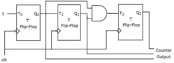
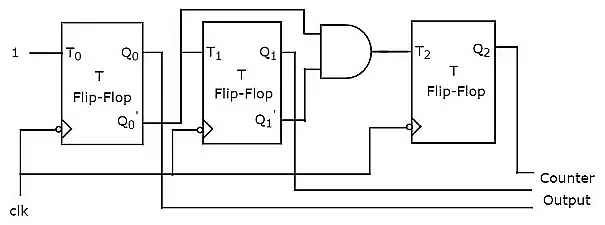
For a 3-bit synchronous up counter implemented with T flip-flops:
- T input of the LSB (T0) is tied to logic 1, so Q0 toggles every clock edge.
- T1 = Q0, so Q1 toggles when Q0 is 1 (i.e. on those clock edges where a carry from LSB occurs).
- T2 = Q1 · Q0, so Q2 toggles only when both lower bits are 1 (i.e. when a carry ripples to the third bit).
General rule for an N-bit synchronous up counter implemented with T flip-flops:
- T0 = 1.
- Ti = Qi-1 · Qi-2 · ... · Q0 for i ≥ 1.
Timing consideration: the maximum allowed clock frequency is limited by the propagation delay through the combinational logic that produces the T inputs and by the flip-flop setup time. Therefore synchronous counters are suitable for higher-speed applications compared with asynchronous ripple counters.
Synchronous Binary Down Counter
An N-bit synchronous binary down counter is similar in approach to the synchronous up counter but the combinational logic is arranged so the count decrements by one on each clock edge. Using T flip-flops, the T inputs are functions of the complements of lower-order bits.
For a 3-bit synchronous down counter with T flip-flops:
- T0 = 1.
- T1 = Q0′, so Q1 toggles when Q0 is 0 (a borrow condition from LSB).
- T2 = Q1′ · Q0′, so Q2 toggles when both lower bits are 0.
General rule for synchronous down counters implemented with T flip-flops:
- T0 = 1.
- Ti = Qi-1′ · Qi-2′ · ... · Q0′ for i ≥ 1.
Design notes, variations and applications
Additional points useful for design and practice:
- Modulo-N counters: both synchronous and asynchronous counters can be made modulo-N by adding combinational logic to detect a terminal count and then asynchronously or synchronously resetting the flip-flops to zero (for example, a modulo-10 BCD counter resets when the count reaches 10).
- Implementation with other flip-flop types: JK or D flip-flops can be used. For D flip-flops, derive D inputs from the present Qs so that the next required state appears at D at the clock edge.
- Asynchronous clear/preset: many counters include asynchronous clear or preset inputs for initialisation or to implement specific sequences; care is required to avoid metastability when these signals change near clock edges.
- Speed vs. complexity trade-off: asynchronous counters are simpler but slower; synchronous counters are faster but require more combinational logic.
- Applications: frequency division, digital clocks, event counting, address generation in memory circuits, and sequencing in control systems.
Summary
Asynchronous (ripple) counters are simple, with clocks applied only to the LSB and higher stages clocked by preceding outputs; they suffer from ripple delays. Synchronous counters provide simultaneous state transitions because all flip-flops share the same clock, and combinational logic controls flip-flop inputs to produce the desired count sequence, allowing higher clock rates and cleaner outputs. Choice between the two depends on speed requirements, hardware complexity and the presence of timing hazards in the target application.


 | Explore Courses for Computer Science Engineering (CSE) exam |
 | Get EduRev Notes directly in your Google search |