Electromagnetic (EM) Induction & Applications of the Generator Effect | Physics for Grade 10 PDF Download
| Table of contents |

|
| Induced potential and the generator effect |

|
| The ac generator |

|
| The dc generator |

|
| Microphones |

|
| Applications of the Generator Effect |

|
Induced potential and the generator effect
A potential difference or voltage is needed to make an electric current flow in a circuit.- a coil of wire is moved in a magnetic field
- a magnet is moved into a coil of wire
This is called electromagnetic induction and is often referred to as the generator effect.
The induced voltage produces an induced current if the conductor is connected in a complete circuit. As with all currents, the induced current creates a magnetic field around itself. Note that this magnetic field opposes the original change. For example, if a magnet is moved into a coil of wire, the induced magnetic field tends to repel the magnet back out of the coil. This effect occurs whether a magnet is moved into a coil, or a coil is moved around a magnet.
Factors affecting the induced potential
The direction of the induced current depends on the direction of movement of the magnet relative to the coil. The current is reversed when:- the magnet is moved out of the coil
- the other pole of the magnet is moved into the coil
- The images illustrate how this works.
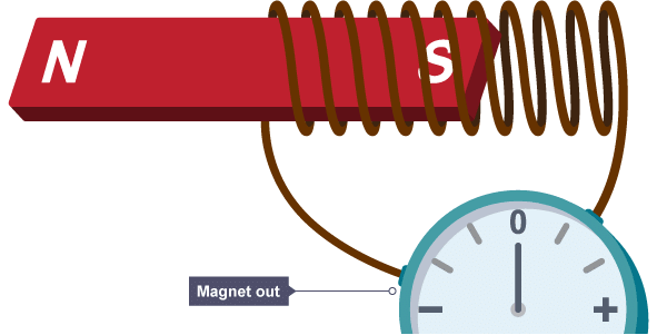
A bar magnet rests outside a wire coil connected to an ammeter showing no current
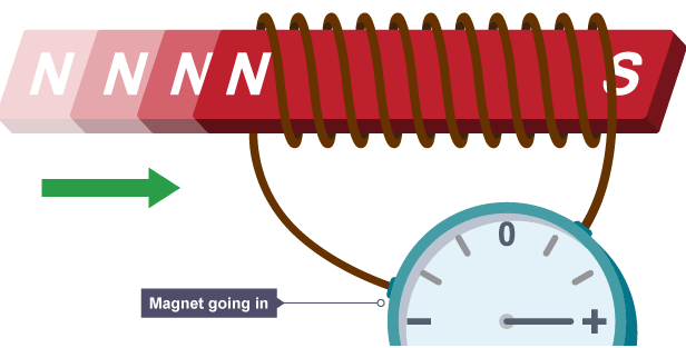
The magnet moves into the coil of wire and the ammeter registers positive current flow
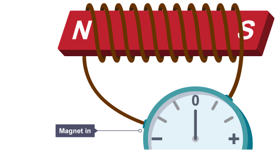
The magnet is stationary within the coil of wire, there is no current flow
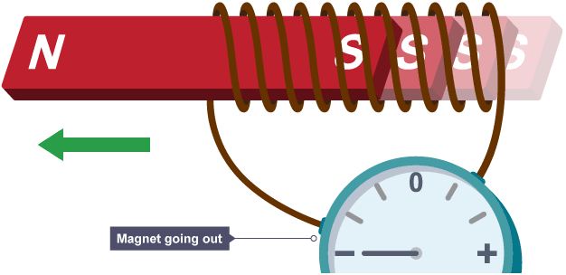
The magnet moves out of the coil of wire and the ammeter registers negative current flow
An induced potential difference or induced current will increase if:
- the speed of movement is increased
- the magnetic field strength is increased
- the number of turns on the coil is increased
The ac generator
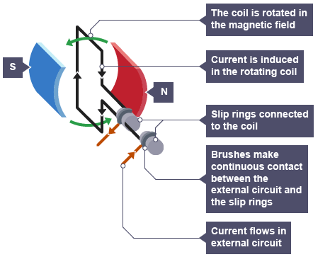
An alternating current (ac) generator is a device that produces a potential difference. A simple ac generator consists of a coil of wire rotating in a magnetic field. Cars use a type of ac generator, called an alternator to keep the battery charged and to run the electrical system while the engine is working.The alternator
The diagram shows a simple alternator.
Alternator output on a graph
The output of an alternator as it rotates can be represented on a potential difference-time graph with potential difference (voltage) on the vertical axis and time on the horizontal axis.The graph shows an alternating sine curve. The maximum potential difference or current can be increased by:
- increasing the rate of rotation
- increasing the strength of the magnetic field
- increasing the number of turns on the coil
The diagram shows four different positions of the coil in an alternator, and the corresponding potential difference produced.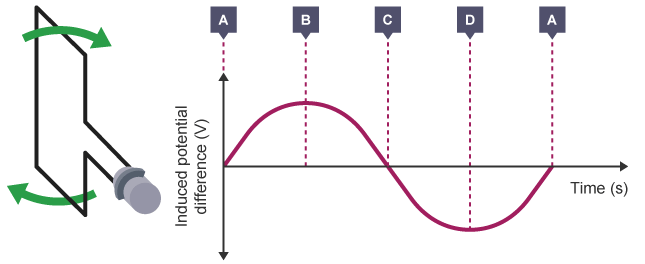 The potential difference-time graph for an alternator
- A - The coil is at 0°. The coil is moving parallel to the direction of the magnetic field, so no potential difference is induced.
- B - The coil is at 90°. The coil is moving at 90° to the direction of the magnetic field, so the induced potential difference is at its maximum.
- C - The coil is at 180°. The coil is moving parallel to the direction of the magnetic field, so no potential difference is induced.
- D - The coil is at 270°. The coil is moving at 90° to the direction of the magnetic field, so the induced potential difference is at its maximum. Here, the induced potential difference travels in the opposite direction to what it did at B.
- A - The coil is at 360°, ie it is back at its starting point, having done a full rotation. The coil is moving parallel to the direction of the magnetic field, so no potential difference is induced.
The dc generator
A direct current (dc) generator is another device that produces a potential difference. A simple dc generator consists of a coil of wire rotating in a magnetic field. However, it uses a split ring commutator rather than the two slip rings found in alternating current (ac) generators. Some bike lights use a type of dc generator called a dynamo to run the lamps while the wheels are turning.The dynamo
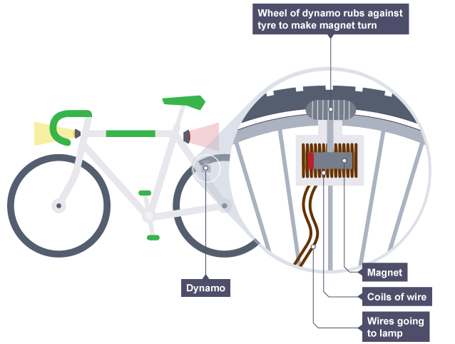 In a bike dynamo, the magnet rotates inside a fixed coil of wire
In a dynamo, a split ring commutator changes the coil connections every half turn. As the induced potential difference is about to change direction, the connections are reversed. This means that the current to the external circuit always flows in the same direction.
Dynamo output on a graph
The output of a rotating dynamo can be shown on a potential difference-time graph. The graph shows a sine curve that stays in the same direction all the time. The maximum potential difference or current can be increased by:- increasing the rate of rotation
- increasing the strength of the magnetic field
- increasing the number of turns on the coil
The diagram shows four different positions of the coil in a dynamo, and the corresponding potential difference produced.
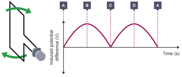 The potential difference-time graph for a dynamo
- A - The coil is at 0°. The coil is moving parallel to the direction of the magnetic field, so no potential difference is induced.
- B - The coil is at 90°. The coil is moving at 90° to the direction of the magnetic field, so the induced potential difference is at its maximum.
- C - The coil is at 180°. The coil is moving parallel to the direction of the magnetic field, so no potential difference is induced.
- D - The coil is at 270°. The coil is moving at 90° to the direction of the magnetic field, so the induced potential difference is at its maximum. Here, the induced potential difference travels in the same direction as at B.
- A - The coil is at 360°, ie it is back at its starting point, having done a full rotation. The coil is moving parallel to the direction of the magnetic field, so no potential difference is induced.
Microphones
The microphone is a device that converts sound waves into electrical signals. Microphones use the generator effect to induce a changing current from the pressure variations of sound waves.Moving-coil microphones
The diagram shows a moving-coil microphone.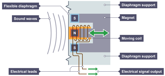 A moving-coil microphone
In a moving-coil microphone:
- pressure variations in sound waves cause the flexible diaphragm to vibrate
- the vibrations of the diaphragm cause vibrations in the coil
- the coil moves relative to a permanent magnet, so a potential difference is induced in the coil
- the coil is part of a complete circuit, so the induced potential difference causes a current to flow around the circuit
- the changing size and direction of the induced current matches the vibrations of the coil
- the electrical signals generated match the pressure variations in the sound waves
Applications of the Generator Effect
- The generator effect can be used to:
- Generate a.c in an alternator
- Generate d.c in a dynamo
Alternator
- A simple alternator is a type of generator that converts mechanical energy to electrical energy in the form of alternating current
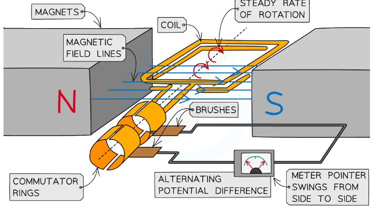 An alternator is a rotating coil in a magnetic field connected to commutator rings
- A rectangular coil that is forced to spin in a uniform magnetic field
- The coil is connected to a centre-reading meter by metal brushes that press on two metal slip rings (or commutator rings)
- The slip rings and brushes provide a continuous connection between the coil and the meter
- When the coil turns in one direction:
- The pointer defects first one way, then the opposite way, and then back again
- This is because the coil cuts through the magnetic field lines and a potential difference, and therefore current, is induced in the coil
- The pointer deflects in both directions because the current in the circuit repeatedly changes direction as the coil spins
- This is because the induced potential difference in the coil repeatedly changes its direction
- This continues on as long as the coil keeps turning in the same direction
- The induced potential difference and the current alternate because they repeatedly change direction
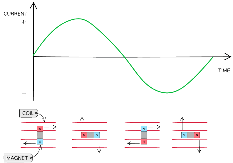 A.C output from an alternator - the current is both in the positive and negative region of the graph
Dynamos
- A dynamo is a direct-current generator
- A simple dynamo is the same as an alternator except that the dynamo has a split-ring commutator instead of two separate slip rings
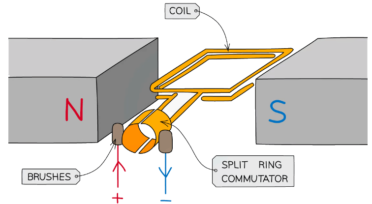 A dynamo is a rotating coil in a magnetic field connected to a split ring commutator
- As the coil rotates, it cuts through the field lines
- This induces a potential difference between the end of the coil
- The split ring commutator changes the connections between the coil and the brushes every half turn in order to keep the current leaving the dynamo in the same direction
- This happens each time the coil is perpendicular to the magnetic field lines
- Therefore, the induced potential difference does not reverse its direction as it does in the alternator
- Instead, it varies from zero to a maximum value twice each cycle of rotation, and never changes polarity (positive to negative)
- This means the current is always positive (or always negative)
Exam Tip
- Motors and generators look very similar (as do microphones and loudspeakers), but they do very different things.
- When tackling a question on either of them, make sure you are writing about the right one! A motor takes in electricity and turns it into motion. A generator takes in motion, and generates electricity.
- You might be expected to give the explanations of how these two things happen - make sure that you understand their subtle differences!
|
122 videos|152 docs|40 tests
|

