Strain Gauges and Rosettes | Strength of Materials (SOM) - Mechanical Engineering PDF Download
| Table of contents |

|
| Introduction |

|
| What is a Strain Gauge? |

|
| Strain Gauge Working Principle |

|
| Types of Strain Gauges |

|
| Solved Numericals |

|
Introduction
A strain gauge is a highly adaptable and commonly used sensor that detects strain or deformation in different materials. It is an essential tool in engineering, crucial for measuring and monitoring mechanical forces and stresses. Strain gauges are employed in various fields, including structural analysis, load testing, material testing, and stress analysis.The core principle of a strain gauge lies in its ability to transform mechanical strain into an electrical signal. The gauge comprises a thin metallic wire affixed to the surface of the material being observed. When the material experiences strain, the gauge deforms, altering the electrical resistance of the metallic element. This resistance change is directly proportional to the applied strain, enabling precise measurements. In this article, we will delve into the details of strain gauges.
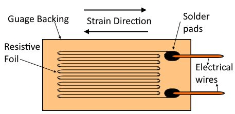 Strain Gauge
What is a Strain Gauge?
- A strain gauge is a device designed to measure the strain or deformation of an object under external forces.
- It is extensively used in solid mechanics to quantify the stress a material undergoes.
- The gauge consists of a wire or foil arranged in a zigzag or grid-like pattern, which experiences changes in electrical resistance when subjected to mechanical strain.
- Strain gauges are widely used in fields such as structural engineering, aerospace, automotive, and materials testing.
- They help monitor and analyze structural behavior, determine material properties, assess structural integrity, and optimize designs.
When an external force is applied to an object, it deforms, altering the length and cross-sectional area of the strain gauge and causing a change in its electrical resistance. This resistance change is directly proportional to the strain experienced by the object. To measure this strain, the strain gauge is typically attached to the object's surface using adhesive or solder. As the object deforms, the strain gauge undergoes the same deformation, resulting in a change in resistance.
Strain Gauge Working Principle
The working principle of a strain gauge is based on the concept of electrical resistance variation due to mechanical strain. Here's a detailed explanation:Strain Gauge Composition:
- The strain gauge consists of a fine wire or foil, typically made of a highly conductive material like copper or constantan.
- This wire or foil is attached to a flexible backing material.
Mechanism of Action:
- When mechanical strain is applied to the strain gauge, the wire or foil deforms.
- This deformation alters the length and cross-sectional area of the wire or foil.
- The change in dimensions leads to a corresponding change in the electrical resistance of the wire or foil.
Measurement Process:
- The change in resistance is measured using a Wheatstone bridge circuit, which is commonly employed in strain gauge applications.
- The Wheatstone bridge consists of four resistive arms, with the strain gauge forming one of the arms. The other three arms typically consist of fixed resistors.
- When the strain gauge experiences a strain, its resistance changes, causing an imbalance in the Wheatstone bridge circuit.
- This imbalance generates a small electrical output signal proportional to the applied strain.
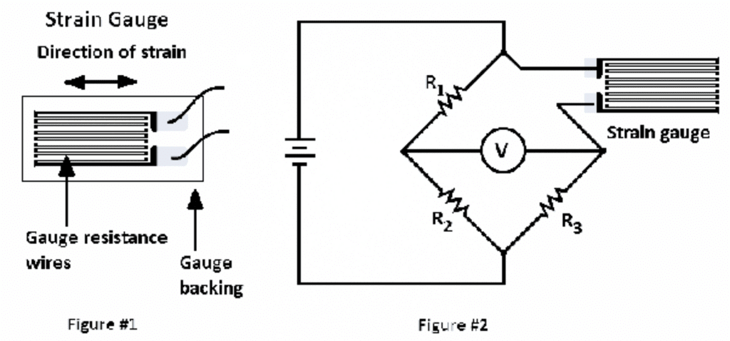
Working of Strain Gauge
Types of Strain Gauges
Strain gauges are essential instruments used to measure and monitor the strain or deformation of structural components. They play a crucial role in assessing the structural integrity and performance of various civil engineering projects. Strain gauges come in different types, each designed to suit specific applications and measurement requirements. Here are the main types:Electrical Resistance Strain Gauges:
- Description: These are the most widely used type in civil engineering applications. They consist of a grid of fine metallic wire or foil bonded to a backing material.
- Working Principle: When subjected to strain, the wire or foil experiences a change in resistance. This change is measured using a Wheatstone bridge circuit.
- Advantages: Electrical resistance strain gauges offer high sensitivity, accuracy, and stability.
- Applications: They are suitable for measuring small strains in structures such as bridges, dams, and buildings.
Vibrating Wire Strain Gauges:
- Description: These strain gauges utilize the principle of the resonant frequency of a wire to measure strain.
- Working Principle: They consist of a taut wire stretched between two anchor points. When subjected to strain, the tension in the wire changes, altering its resonant frequency. By measuring the frequency change, the strain can be determined.
- Advantages: Vibrating wire strain gauges are robust, offer long-term stability, and are resistant to environmental factors.
- Applications: They are particularly useful in geotechnical and structural monitoring applications.
Fiber Optic Strain Gauges:
- Description: These gauges utilize optical fibers to measure strain.
Working Principle: They operate based on the phenomenon of strain-induced change in the light transmission characteristics of the fiber. The fiber optic sensor consists of a section of optical fiber embedded or bonded to the structure being monitored. As strain is applied, it alters the light intensity or wavelength propagating through the fiber, which is then detected and analyzed. - Advantages: Fiber optic strain gauges offer high accuracy, immunity to electromagnetic interference, and the ability to multiplex multiple sensors along a single fiber.
- Applications: They are used in environments where high precision is required and in conditions where electromagnetic interference is a concern.
Piezoelectric Strain Gauges:
- Description: These gauges employ the piezoelectric effect to measure strain.
- Working Principle: They consist of a piezoelectric crystal or ceramic material that generates an electric charge when subjected to mechanical deformation. This charge is proportional to the applied strain and can be measured using specialized equipment.
- Advantages: Piezoelectric strain gauges are highly sensitive and capable of measuring dynamic strains.
- Limitations: They are susceptible to temperature variations and have a limited range of linearity.
- Applications: They are used in structures such as bridges, tunnels, and pavements where dynamic strain measurements are necessary.
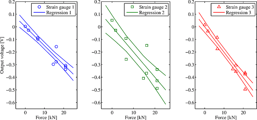
Calibration of Strain Gauge
What is a Strain Gauge Rossete
Strain rosettes are used in strain analysis, particularly in the biaxial state of stress. They are essential because a single strain gauge can measure strain in only one direction, but strain analysis often requires knowing strain in multiple directions. Strain rosettes are arrangements of strain gauges in three arbitrary directions to measure normal strains in those directions. Based on their arrangement, strain rosettes are classified into three types:
- Rectangular Strain Gauge Rosette
- Delta Strain Gauge Rosette
- Star Strain Gauge Rosette
1. Rectangular Strain Gauge Rosette
A rectangular strain rosette consists of three strain gauges arranged at 0°, 45°, and 90° angles.
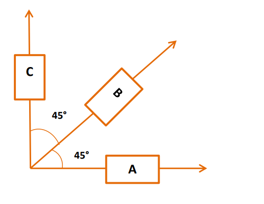
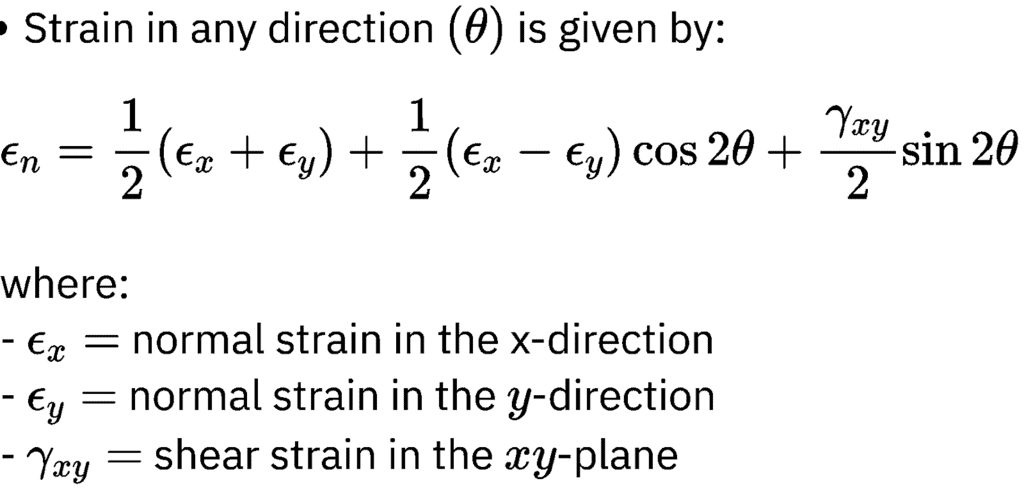
Strain in any direction (θ) is given by:
Normal strain at θ = 0°:
Normal strain at θ = 45°:
From this we get, 
Normal strain at θ = 90°:
Shear strain:
With a rectangular strain rosette, we can determine ϵx, ϵy and γxy, allowing us to calculate the principal strains on the surface of an object.
2. Delta Strain Gauge Rosette
A delta strain rosette also consists of three strain gauges, arranged at 0°, 60°, and 120°.
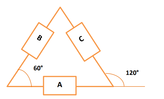
Normal strain at θ = 0°:
Normal strain at θ = 60°:
Normal strain at θ = 120°:
3. Star Strain Gauge Rosette
A star strain rosette consists of three strain gauges arranged at 0°, 120°, and 240°.
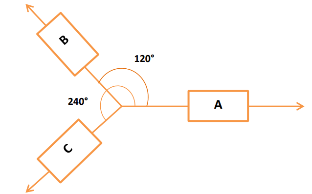
Normal strain at θ = 0°:
Normal strain at θ = 120°:
Normal strain at θ = 240°:

Solved Numericals
Question S-1. Determine maximum shear stress at a point by using the following strain gauge readings of rectangular strain rosette

Solution:
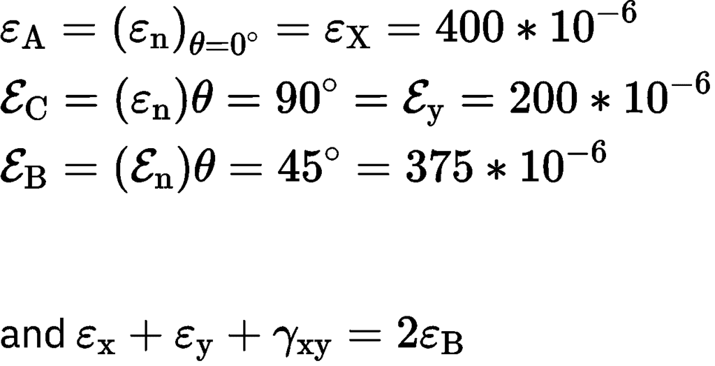

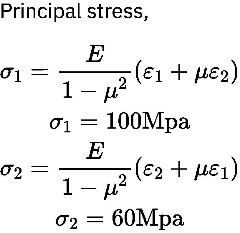

Absolute τmax =  = 50 MPa
|
37 videos|39 docs|45 tests
|
FAQs on Strain Gauges and Rosettes - Strength of Materials (SOM) - Mechanical Engineering
| 1. What is the working principle of a strain gauge? |  |
| 2. What are the different types of strain gauges available? |  |
| 3. How does a rosette strain gauge differ from a regular strain gauge? |  |
| 4. How are strain gauges typically calibrated for accurate measurements? |  |
| 5. Can strain gauges be used to measure both tensile and compressive strains in a material? |  |

|
Explore Courses for Mechanical Engineering exam
|

|


