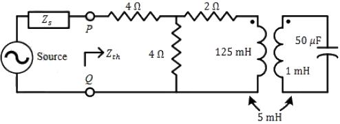
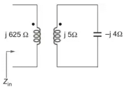
Q1: For the circuit shown in the figure, the source frequency is 5000 rad/sec. The mutual inductance between the magnetically coupled inductors is 5mH with their self inductances being 125mH and 1mH. The Thevenin's impedance. Zth, between the terminals P and Q in Ω is _____ (rounded off to 2 decimal places). (2024)
 (a) 5.33
(b) 4.55
(c) 6.25
(d) 7.58
Ans: (a)
Sol: 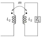
Q2: The transfer function of a real system, H(s), is given as:
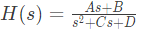 where A, B, C and D are positive constants. This system cannot operate as (2022)
(a) low pass filter.
(b) high pass filter
(c) band pass filter.
(d) an integrator.
Ans: (b, d)
Sol: Put  So, the system pass low frequency component. Put s = ∞, H(∞) = 0
For high pass filter, high frequency component should be non zero. Hence this system cannot be operated as high pass filter.
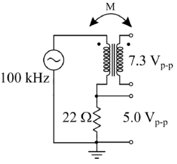
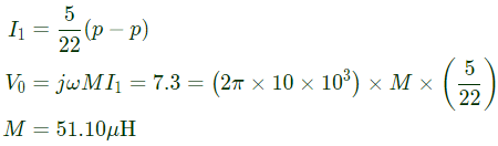
Q3: An air-core radio-frequency transformer as shown has a primary winding and a secondary winding. The mutual inductance M between the windings of the transformer is ____________ μH.(Round off to 2 decimal places.) (2021)
 (a) 12.14
(b) 68.26
(c) 51.1
(d) 78.4
Ans: (c)
Sol: 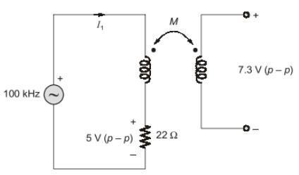
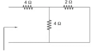
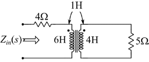
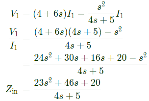
Q4: The input impedance, Zin (s) for the network shown is (2021)
 (a)
(a) 
(b) 6s + 4
(c) 7s + 4
(d) 
Ans: (a)
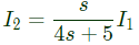
Sol: Circuit in s-domain,
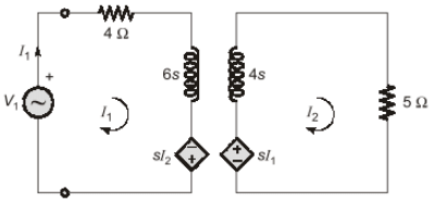
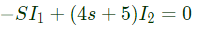 ⇒
⇒ 
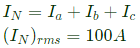
Q5: The line currents of a three-phase four wire system are square waves with amplitude of 100 A. These three currents are phase shifted by 120° with respect to each other. The rms value of neutral current is (2019)
(a) 0 A
(b) 
(c) 100 A
(d) 300 A
Ans: (c)
Sol: 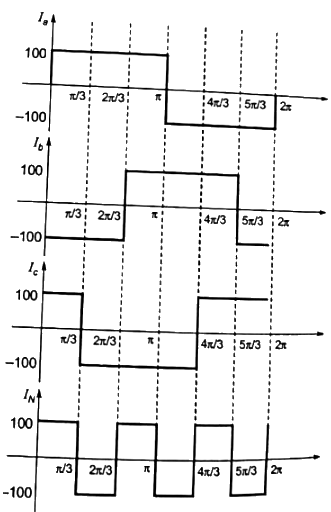
Q6: The graph of a network has 8 nodes and 5 independent loops. The number of branches of the graph is (2018)
(a) 11
(b) 12
(c) 13
(d) 14
Ans: (b)
Sol: Loops = b - (N-1)
5 = b-(8-1)
b = 12
Q7: The graph associated with an electrical network has 7 branches and 5 nodes. The number of independent KCL equations and the number of independent KVL equations, respectively, are (SET-2 (2016))
(a) 2 and 5
(b) 5 and 2
(c) 3 and 4
(d) 4 and 3
Ans: (d)
Sol: Number of KCL equations
= n - 1 = 5 - 1 = 4
Number of KVL equations
= b - (n - 1) = 7 - (5 - 1) = 3
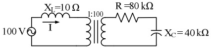
Q8: The following figure shows the connection of an ideal transformer with primary to secondary turns ratio of 1 : 100. The applied primary voltage is 100 V (rms), 50 Hz, AC. The rms value of the current I, in ampere, is __________. (SET-2 (2016))
 (a) 100
(b) 10
(c) 20
(d) 50
Ans: (b)
Sol: The above circuit can be drown by transferring secondary circuit to primary side.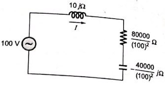
 So the rms value of I will be 10 A.
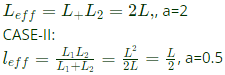
Q9: Two identical coils each having inductance L are placed together on the same core. If an overall inductance of αL is obtained by interconnecting these two coils, the minimum value of α is ____. (SET-2 (2015))
(a) 0
(b) 0.25
(c) 0.5
(d) 0.75
Ans: (a)
Sol: CASE-I:
 CASE-III
If both are diffferentially coupled then
 Minimum value = 0
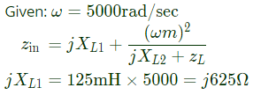
Q10: Find the transformer ratios a and b such that the impedance (Zin) is resistive and equals 2.5Ω when the network is excited with a sine wave voltage of angular frequency of 5000 rad/s. (SET-2 (2015))
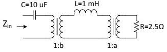 (a) a = 0.5, b = 2.0
(b) a = 2.0, b = 0.5
(c) a = 1.0, b = 1.0
(d) a = 4.0, b = 0.5
Ans: b
Sol: 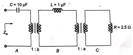
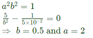
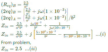 From equation (i) and (ii),
Q11: Two identical coupled inductors are connected in series. The measured inductances for the two possible series connections are 380 μH and 240 μH. Their mutual inductance in μH is _____. (SET-2 (2014))
(a) 10
(b) 15
(c) 55
(d) 35
Ans: (d)
Sol: The two possible series connection are shown below:
Let the mutual inductance be M
 (i) Additive connection,
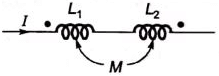 (ii) Substractive connection,
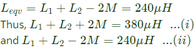 Solving equations (i) and (ii), we get:
4M = 140 μH
M = 35 μH
Therefore, mutual inductance M = 35μH
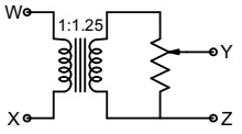
Q12: The following arrangement consists of an ideal transformer and an attenuator which attenuates by a factor of 0.8. An ac voltage VWX1 = 100 V is applied across WX to get an open circuit voltage VYZ1 across YZ. Next, an ac voltage VYZ2 = 100 V is applied across YZ to get an open circuit voltage VWX2 across WX. Then, VYZ1 / VWX1, VWX2 / VYZ2 are respectively, (2013)
 (a) 125/100 and 80/100
(b) 100/100 and 80/100
(c) 100/100 and 100/100
(d) 80/100 and 80/100
Ans: (b)
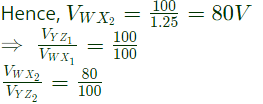
Sol: VYZ1 = 100 × 1.25 × 0.8 = 100
In second case when 100 V is applied at YZ terminals, this whole 100 V will appear across the secondary winding,
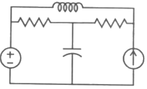
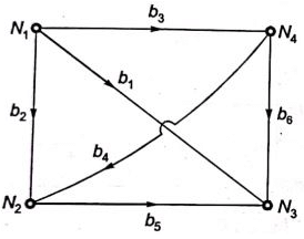
Q13: The number of chords in the graph of the given circuit will be (2008)
 (a) 3
(a) 3
(b) 4
(c) 5
(d) 6
Ans: (a)
Sol: 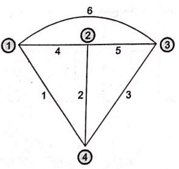 Number of branches = b = 6
No. of nodes = n = 4
No. of chords = b - (n - 1) =6 - (4 - 1) = 3
Q14: The matrix A given below in the node incidence matrix of a network. The columns correspond to branches of the network while the rows correspond to nodes. Let V= [v1 v2 ... v6]T denote the vector of branch voltages while I = [i1 i2 ... i6]T that of branch currents. The vector E = [e1 e2 e3 e4]T denotes the vector of node voltages relative to a common ground.
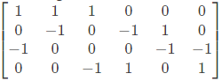 Which of the following statement is true ? (2007)
(a) The equations v1 - v2 + v3 = 0, v3 + v4 - v5 = 0 are KVL equations for the network for some loops
(b) The equations v1 - v3 - v6 = 0, v4 + v5 - v6 = 0 are KVL equations for the network for some loops
(c) E = AV
(d) AV = 0 are KVI equations for the network
Ans: (b)
Sol: Convention:
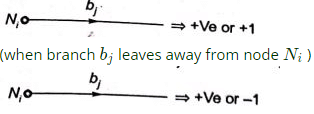 (when branch bj enters node Ni)
Given node incidence matrix
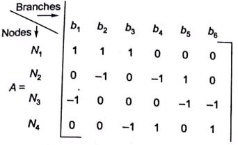 eg.: Branch b1 enter N3 and leaves N1
The oriented network graph
 Using KVL, in loop containing branches b1, b3 and b6
v1 - v6 - v3 = 0
In loop containing branches b4, b5 and b6
v4 + v5 - v6 = 0
Q15: In the circuit shown in figure, it is found that the input ac voltage (Vi) and current i are in phase. The coupling coefficient is  where M is the mutual inductance between the two coils. The value of K and the dot polarity of the coil P-Q are (2002)
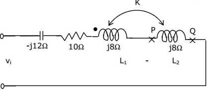 (a) K = 0.25 and dot at P
(b) K = 0.5 and dot at P
(c) K = 0.25 and dot at Q
(d) K = 0.5 and dot at Q
Ans: c
Sol: Input ac voltage and current will be in phase only at resonance condition,
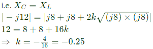 Hence, coupling will be opposite.
Therefore, Dot will be at Q.
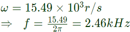
Q16: A first order, low pass filter is given with R = 50 Ω and C = 5μF. What is the frequency at which the gain of the voltage transfer function of the filter is 0.25? (2002)
(a) 4.92 kHz
(b) 0.49 kHz
(c) 2.46 kHz
(d) 24.6 kHz
Ans: (c)
Sol: 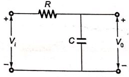
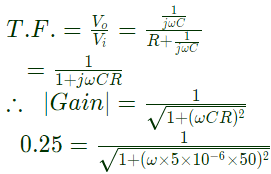 On solving,
Q17: The graph of an electrical network has N nodes and B branches. The number of links, L, with respect to the choice of a tree, is given by (2002)
(a) B - N + 1
(b) B + N
(c) N - B + 1
(d) N - 2B -1
Ans: (a)
Sol: Number of links = B - (N - 1) = B - N + 1
Q18: A connected network of N > 2 nodes has at most one branch directly connecting any pair of nodes. The graph of the network (2001)
(a) must have at least N branches for one or more closed paths to exist
(b) can have an unlimited number of branches
(c) can only have at most N branches
(d) can have a minimum number of branches not decided by N
Ans: (a)
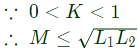
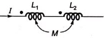
Q19: Given two coupled inductors L1 and L2, their mutual inductance M satisfies (2001)
(a) 
(b) 
(c) 
(d) 
Ans: (d)
Sol:  where , K= coefficient of coupling