Q1: A single-phase triac based AC voltage controller feeds a series RL load. The input AC supply is 230 V, 50 Hz. The values of R and L are 10Ω and 18.37mH, respectively. The minimum triggering angle of the triac to obtain controllable output voltage is (2024)
(a) 15°
(b) 30°
(c) 45°
(d) 60°
Ans: (b)
Sol: Output voltage is controlled if
 θ = 29.989°
So, αmin can be 30°.
Q2: The single phase rectifier consisting of three thyristors T1, T2, T3 and a diode D1 feed power to a 10 A constant current load. T1 and T3 are fired at α = 60° and T2 is fired at α = 240°. The reference for α is the positive zero crossing of Vin. The average voltage Vo across the load in volts is _____ (Round off to 2 decimal places). (2023)
 (a) 25.35
(b) 36.47
(c) 39.79
(d) 48.64
Ans: (c)
Sol:  ∴ Average output voltage,

 Put the values,

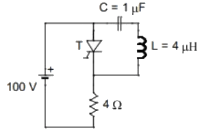
Q3: The circuit shown in the figure has reached steady state with thyristor 'T' in OFF condition. Assume that the latching and holding currents of the thyristor are zero.
The thyristor is turned ON at t = 0 sec. The duration in microseconds for which the thyristor would conduct, before it turns off, is ___ (Round off to 2 decimal places). (2023)
 (a) 7.33
(b) 5.36
(c) 4.25
(d) 8.23
Ans: (a)
Sol: Case (i) t < 0 sec :
Steady state circuit :
 Case (ii) t > 0 sec:
Thyristor is ON
Redraw the circuit :

 ∴ Current through thyristor :
 When IT = 0 ⇒ Thyristor is turn off.

Q4: For the ideal AC-DC rectifier circuit shown in the figure below, the load current magnitude is Idc = 15A and is ripple free. The thyristors are fired with a delay angle of 45°. The amplitude of the fundamental component of the source current, in amperes, is __________. (round off to two decimal places) (2022)
 (a) 12.45
(b) 25.32
(c) 14.25
(d) 17.64
Ans: (d)
Sol: Given rectifier circuit is a 1 − ϕ semiconverter Waveform of source current:

 Now, fundamental component,

Q5: The voltage at the input of an AC - DC rectifier is given by v(t) = 230√2 sin ωt where ω = 2π × 50 rad/s. The input current drawn by the rectifier is given by
The input power factor, (rounded off to two decimal places), is, _________ lag. (2022)
(a) 0.44
(b) 0.22
(c) 0.66
(d) 0.88
Ans: (a)
Sol: We have,


Q6: A single-phase full-bridge diode rectifier feeds a resistive load of 50Ω from a 200V, 50Hz single phase AC supply. If the diodes are ideal, then the active power, in watts, drawn by the load is _____________. (round off to nearest integer). (2022)
(a) 200
(b) 1600
(c) 600
(d) 800
Ans: (d)
Sol: For 1 − ϕ full bridge diode rectifier:
 Active power drawn by the load

Q7: The waveform shown in solid line is obtained by clipping a full-wave rectified sinusoid (shown dashed). The ratio of the RMS value of the full-wave rectified waveform to the RMS value of the clipped waveform is _______________. (Round off to 2 decimal places.) (2021)
 (a) 1.21
(b) 2.24
(c) 1.82
(d) 0.65
Ans: (a)
Sol:  We know,
RMS value of full wave rectified sine 
For clipped wave form
As  wave form are identical
rms value of clipped wave
 Ratio = 0.707/0.5838 = 1.21
Q8: In the circuit shown, the input Vi is a sinusoidal AC voltage having an RMSRMS value of 230V ± 20%. The worst-case peak-inverse voltage seen across any diode is _____V. (Round off to 2 decimal places.) (2021)
 (a) 390.32
(b) 124.25
(c) 258.36
(d) 471.56
Ans: (a)
Sol: 

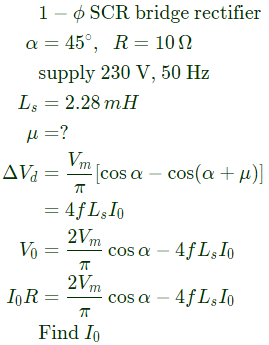
Q9: A single-phase, full-bridge, fully controlled thyristor rectifier feeds a load comprising a 10 Ω resistance in series with a very large inductance. The rectifier is fed from an ideal 230 V, 50 Hz sinusoidal source through cables which have negligible internal resistance and a total inductance of 2.28 mH. If the thyristors are triggered at an angle α = 45°, the commutation overlap angle in degree (rounded off to 2 decimal places) is_____. (2020)
(a) 2.4
(b) 4.8
(c) 64
(d) 8.2
Ans: (b)
Sol: 


Q10: Consider the diode circuit shown below. The diode, D, obeys the current-voltage characteristic ID =  where n > 1, VT > 0, VD is the voltage across the diode and ID is the current through it. The circuit is biased so that voltage, V > 0 and current, I < 0. If you had to design this circuit to transfer maximum power from the current source (I1) to a resistive load (not shown) at the output, what values R1 and R2 would you choose? (2020)
 (a) Large R1 and large R2.
(b) Small R1 and small R2.
(c) Large R1 and small R2.
(d) Small R1 and large R2.
Ans: (d)
Sol:  So for maximum power, R1 is small and R2 is large.
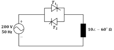
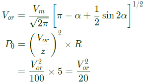
Q11: Thyristor T1 is triggered at an angle α (in degree), and T2 at angle 180° + α, in each cycle of the sinusoidal input voltage. Assume both thyristors to be ideal. To control the load power over the range 0 to 2 kW, the minimum range of variation in α is: (2020)
 (a) 0° to 60°
(b) 0° to 120°
(c) 60° to 120°
(d) 60° to 180°
Ans: (b)
Sol: As per GATE official answer key, MTA (Marks to All)
 As load is capacitive, for any α :


 For α = 120°, as current distinguishes, so P = 0.
So, α should be 0° to 120°.
Q12: A single-phase, full-bridge diode rectifier fed from a 230 V, 50 Hz sinusoidal source supplies a series combination of finite resistance. R, and a very large inductance, L, The two most dominant frequency components in the source current are: (2020)
(a) 50 Hz, 0 Hz
(b) 50 Hz, 100 Hz
(c) 50 Hz, 150 Hz
(d) 50 Hz, 250 Hz
Ans: (c)
Sol: For full bridge rectifier, High inductive load

 Since the most dominant frequency component will be f, 3f, f = 50
So dominant frequency = 50Hz, 150Hz.
Q13: A single-phase fully-controlled thyristor converter is used to obtain an average voltage of 180 V with 10 A constant current to feed a DC load. It is fed from single-phase AC supply of 230 V, 50 Hz. Neglect the source impedance. The power factor (round off to two decimal places) of AC mains is________ (2019)
(a) 0.25
(b) 0.55
(c) 0.78
(d) 0.95
Ans: (c)
Sol: 
For single-phase fully controlled converter,

Q14: A fully-controlled three-phase bridge converter is working from a 415V, 50 Hz AC supply. It is supplying constant current of 100 A at 400 V to a DC load. Assume large inductive smoothing and neglect overlap. The rms value of the AC line currentin amperes (round off to two decimal places) is ________. (2019)
(a) 81.65
(b) 41.25
(c) 66.45
(d) 69.85
Ans: (a)
Sol: AC line current rms 
Q15: A six-pulse thyristor bridge rectifier is connected to a balanced three-phase, 50Hz AC source. Assuming that the DC output current of the rectifier is constant, the lowest harmonic component in the AC input current is (2019)
(a) 100Hz
(b) 150Hz
(c) 250Hz
(d) 300Hz
Ans: (c)
Sol: For 6 pulse converter harmonics present in AC current are 6k ± 1
Lowest order harmonic = 5
Lowest harmonic frequency = 5 x 50 = 250Hz
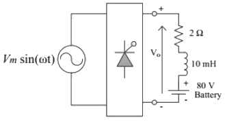
Q16: A phase controlled single phase rectifier, supplied by an AC source, feeds power to an R-L-E load as shown in the figure. The rectifier output voltage has an average value given by  where Vm = 80π volts and α is the firing angle. If the power delivered to the lossless battery is 1600 W, α in degree is________ (up to 2 decimal places). (2018)
 (a) 45
(b) 90
(c) 60
(d) 30
Ans: (b)
Sol: 

Q17: The waveform of the current drawn by a semi-converter from a sinusoidal AC voltage source is shown in the figure. If I0 = 20 A, the rms value of fundamental component of the current is ___________A (up to 2 decimal places). (2018)
 (a) 17.39
(b) 18.92
(c) 24.67
(d) 14.86
Ans: (a)
Sol:
Q18: A single phase fully controlled rectifier is supplying a load with an anti-parallel diode as shown in the figure. All switches and diodes are ideal. Which one of the following is true for instantaneous load voltage and current? (2018)
 (a)
(a) 
(b) 
(c) 
(d)
Ans: (c)
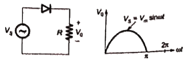
Q19: In the circuit shown in the figure, the diode used is ideal. The input power factor is _______. (Give the answer up to two decimal places.) (SET-2 (2017))
 (a) 0.55
(b) 0.25
(c) 0.71
(d) 0.95
Ans: (c)
Sol: 

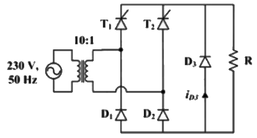
Q20: The figure below shows the circuit diagram of a controlled rectifier supplied from a 230 V, 50 Hz, 1-phase voltage source and a 10:1 ideal transformer. Assume that all devices are ideal. The firing angles of the thyristors T1 and T2 are 90° and 270°, respectively.
 The RMS value of the current through diode D3 in amperes is ____ (SET-2 (2017))
(a) 0
(b) 1
(c) 2
(d) 3
Ans: (a)
Sol: Diode current,
ID3(rms) = 0
FD will not conduct for resistive load.
 θ = 29.989°
 (a) 25.35
 ∴ Average output voltage,
 Put the values,
 (a) 7.33
 Case (ii) t > 0 sec:
 ∴ Current through thyristor :
 When IT = 0 ⇒ Thyristor is turn off.
 (a) 12.45
 Now, fundamental component,


 Active power drawn by the load
 (a) 1.21
 We know,
 wave form are identical
 Ratio = 0.707/0.5838 = 1.21
 (a) 390.32



 where n > 1, VT > 0, VD is the voltage across the diode and ID is the current through it. The circuit is biased so that voltage, V > 0 and current, I < 0. If you had to design this circuit to transfer maximum power from the current source (I1) to a resistive load (not shown) at the output, what values R1 and R2 would you choose? (2020)
 (a) Large R1 and large R2.
 So for maximum power, R1 is small and R2 is large.
 (a) 0° to 60°
 As load is capacitive, for any α :
 For α = 120°, as current distinguishes, so P = 0.
 Since the most dominant frequency component will be f, 3f, f = 50


 where Vm = 80π volts and α is the firing angle. If the power delivered to the lossless battery is 1600 W, α in degree is________ (up to 2 decimal places). (2018)
 (a) 45

 (a) 17.39
 (a)
(a) 


 (a) 0.55

 The RMS value of the current through diode D3 in amperes is ____ (SET-2 (2017))


