Previous Year Questions- Power System Stability - 2 | Power Systems - Electrical Engineering (EE) PDF Download
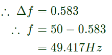
Q16: An isolated 50 Hz synchronous generator is rated at 15 MW which is also the maximum continuous power limit of its prime mover. It is equipped with a speed governor with 5% droop. Initially, the generator is feeding three loads of 4 MW each at 50 Hz. One of these loads is programmed to trip permanently if the frequency falls below 48 Hz .If an additional load of 3.5 MW is connected then the frequency will settle down to (2007)
(a) 49.417Hz
(b) 49.917Hz
(c) 50.083Hz
(d) 50.583Hz
Ans: (c)
Sol: Here, change in (frequency) w.r.t. to power
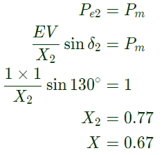
Q17: Consider a synchronous generator connected to an infinite bus by two identical parallel transmission line. The transient reactance 'x' of the generator is 0.1 pu and the mechanical power input to it is constant at 1.0 pu. Due to some previous disturbance, the rotor angle (δ) is undergoing an undamped oscillation, with the maximum value of δ(t) equal to 130°. One of the parallel lines trip due to the relay maloperation at an instant when δ(t) = 130° as shown in the figure. The maximum value of the per unit line reactance, x such that the system does not lose synchronism subsequent to this tripping is (2007) (a) 0.87
(b) 0.74
(c) 0.67
(d) 0.54
Ans: (c)
Sol: The curve Pe1 and Pe2 represents power before the tripping of one line and after the tripping respectively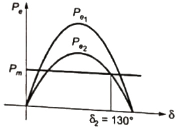
 for max value of X system will not loose synchronization, if at δ2
Q18: A generator feeds power to an infinite bus through a double circuit transmission line. A 3-phase fault occurs at the middle point of one of the lines. The infinite bus voltage of the generator is 1.1 pu and the equivalent transfer admittance during fault is 0.8 pu. The 100 MVA generator has an inertia constant of 5 MJ/MVA and it was delivering 1.0 pu power prior of the fault with rotor power angle of 30°. The system frequency is 50 Hz.
If the initial accelerating power is X pu, the initial acceleration in elect deg/sec2, and the inertia constant in MJ-sec/elect deg respectively will be (2006)
(a) 31.4X, 18
(b) 1800X, 0.056
(c) X/1800, 0.056
(d) X/31.4, 18
Ans: (b)
Sol: Inertia constant (in MJ-s/elec deg) where,
G = Machine rating = 100MVA
H = Ineria constant in MJ/MVA = 5 MJ/MVA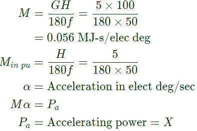

Q19: A generator feeds power to an infinite bus through a double circuit transmission line. A 3-phase fault occurs at the middle point of one of the lines. The infinite bus voltage of the generator is 1.1 pu and the equivalent transfer admittance during fault is 0.8 pu. The 100 MVA generator has an inertia constant of 5 MJ/MVA and it was delivering 1.0 pu power prior of the fault with rotor power angle of 30°. The system frequency is 50 Hz.
The initial accelerating power (in pu) will be (2006)
(a) 0
(b) 0.6
(c) 0.56
(d) 0.4
Ans: (c)
Sol: Before fault:
Electrical power delivered by the generator = Pe = 1.0p.u.
Mechanical input to the generator = Pm
At steady state, During Fault:
Initial rotorr angle = δ = 30°
Internal voltage of the generator = ∣Eg∣ = 1.1p.u.
Voltage of the bus = ∣V∣ = 1p.u.
Equivalent transfer admittance = 0.8
Transfer reactance 
(Pe)f = Electrical power delivered by the generator Mechanical input do not change during fault
So, (Pm)f = 1p.u.
Accelerating power 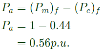
Q20: A generator with constant 1.0 p.u. terminal voltage supplies power through a step-up transformer of 0.12 p.u. reactance and a double-circuit line to an infinite bus bar as shown in the figure. The infinite bus voltage is maintained at 1.0 p.u. Neglecting the resistances and suspectances of the system, the steady state stability power limit of the system is 6.25 p.u. If one of the double-circuit is tripped, then resulting steady state stability power limit in p.u. will be (2005) (a) 12.5 p.u.
(b) 3.125 p.u.
(c) 10.0 p.u.
(d) 5.0 p.u.
Ans: (d)
Sol: Induced emf of the generator = ∣tg∣ = 1p.u.
Termincal voltage = ∣Vt∣ = 1p.u.
Reactance of transformer = Xt = 0.12p.u.
When double-circuit line is connected
Reactance of line= X ||X = X/2
Steady state stability power limit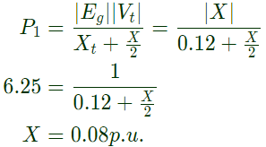 When one of the double circuit is tripled, steady state stability power limit
Q21: An 800 kV transmission line has a maximum power transfer capacity of P. If it is operated at 400 kV with the series reactance unchanged, the new maximum power transfer capacity is approximately (2005)
(a) P
(b) 2P
(c) P/2
(d) P/4
Ans: (d)
Sol: Power transfer capacity ∝ V2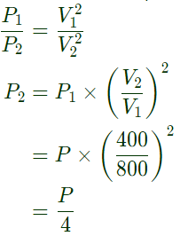
Q22: A 50 Hz, 4-pole, 500 MVA, 22 kV turbo-generator is delivering rated megavoltamperes at 0.8 power factor. Suddenly a fault occurs reducing in electric power output by 40%. Neglect losses and assume constant power input to the shaft. The accelerating torque in the generator in MNm at the time of fault will be (2004)
(a) 1.528
(b) 1.018
(c) 0.848
(d) 0.509
Ans: (b)
Sol: Before fault, mechanical input (Pm) = Electrical output (Pe)
= 500 × 0.8 = 400MW
After fault, mechanical input remains same = Pm = 400MW
While electrical output reduces by 40 %.
So, electrical output at the time of fault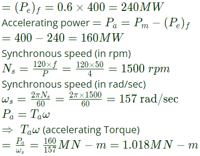
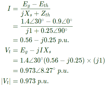
Q23: A new generator having Eg = 1.4∠30° pu [equivalent to (1.212 + j0.70) pu] and synchronous reactance 'Xs' of 1.0 pu on the system base, is to be connected to a bus having voltage Vt in the existing power system. This existing power system can be represented by Thevenin's voltage Eth = 0.9∠0° pu in series with Thevenin's impedance Zth = 0.25∠90° pu. The magnitude of the bus voltage Vt of the system in pu will be (2004)
(a) 0.99
(b) 0.973
(c) 0.963
(d) 0.9
Ans: (b)
Sol: Thevenin's equivalent of existing system,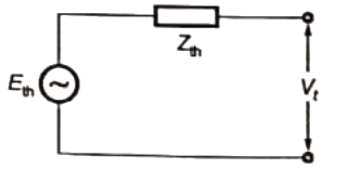 where,
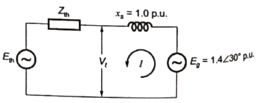
Q24: A 800 kV transmission line is having per phase line inductance of 1.1 mH/km and per phase line capacitance of 11.68 nF/km. Ignoring the length of the line, its ideal power transfer capability in MW is (2004)
(a) 1204 MW
(b) 1504 MW
(c) 2085 MW
(d) 2606 MW
Ans: (c)
Sol: Parameter of the line
Inductance = L = 1.1 mH/km
Capacitance = C =11.68 nF/km
Surge impedance of the line Ideal power transfer capability
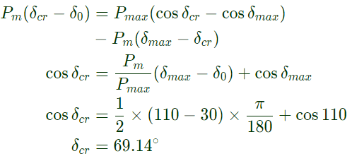
Q25: A generator delivers power of 1.0 p.u. to an infinite bus through a purely reactive network. The maximum power that could be delivered by the generator is 2.0 p.u. A three-phase fault occurs at the terminals of the generator which reduces the generator output to zero. The fault is cleared after tc second. The original network is then restored. The maximum swing of the rotor angle is found to be δmax = 110 electrical degree. Then the rotor angle in electrical degrees at t = tc is (2003)
(a) 55
(b) 70
(c) 69.14
(d) 72.4
Ans: (c)
Sol:  Power generated by the generator
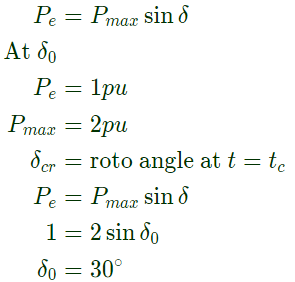 During fault, Pe become zero and the fault is cleared at δcr, Mechanical input to the generator remains constant, Pm = 1pu
Applying equal areal criterion,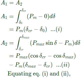
Q26: A transmission line has a total series reactance of 0.2 pu. Reactive power compensation is applied at the midpoint of the line and it is controlled such that the midpoint voltage of the transmission line is always maintained at 0.98 pu. If voltage at both ends of the line are maintained at 1.0 pu, then the steady state power transfer limit of the transmission line is (2002)
(a) 9.8 pu
(b) 4.9 pu
(c) 19.6 pu
(d) 5 pu
Ans: (a)
Sol: 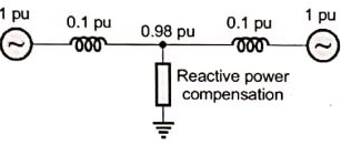

|
21 videos|67 docs|45 tests
|
FAQs on Previous Year Questions- Power System Stability - 2 - Power Systems - Electrical Engineering (EE)
| 1. What is power system stability? |  |
| 2. What are the factors that can affect power system stability? |  |
| 3. How is power system stability maintained in a power grid? |  |
| 4. What are the different types of power system stability issues? |  |
| 5. How can power system stability be improved? |  |


