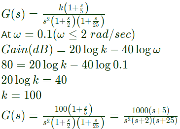
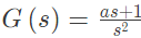
Q21: For the transfer function 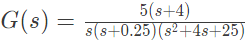 The values of the constant gain term and the highest corner frequency of the Bode plot respectively are (SET-2 (2014))
(a) 3.2, 5.0
(b) 16.0, 4.0
(c) 3.2, 4.0
(d) 16.0, 5.0
Ans: (a)
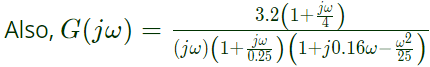
Sol:  Reducing G(s) in time constant form, we have:
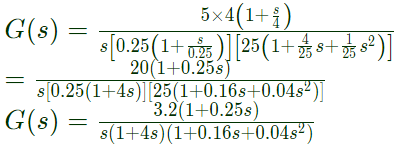 ∴ The value of constant gain term = 3.2
 Corner frequencies are:
ω1 = 4 rad/sec
ω2 = 0.25 rad/sec
ω3 = 5 rad/sec
∴ Highest corner frequency = ω3 =5 rad/sec
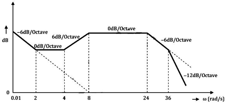
Q22: The Bode magnitude plot of the transfer function 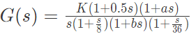 is shown below:
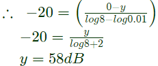
Note that -6 dB/octave = - 20 dB/decade. The value of (a/bK) is _____. (SET-1 (2014))
 (a) 0.48
(b) 0.76
(c) 0.92
(d) 0.28
Ans: (b)
Sol: Given, 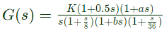
(1+as) is addition of zero to the transfer function whose contribution in slope = +20 dB/decade or -6 dB/octave.
(1+bs) is addition of pole to the transfer function whose contribution in slope = -20 dB/decade or -6 dB/octave.
Observing the change in the slope at different corner frequencies, we conclude that,
a = 1/4 rad/s and b = 1/24 rad/s
From ω = 0.01 rad/s to ω = 8 rad/s,
slope = -20dB/decade
Let the vertical length in dB by y
 Applying, y - mx + C at ω = 0.01 rad/s,
We have, 58 = -20log 0.01 + C
C = 58 - 40 = 18
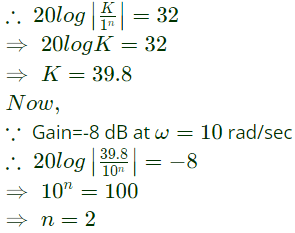
Q23: The Bode plot of a transfer function G(s) is shown in the figure below.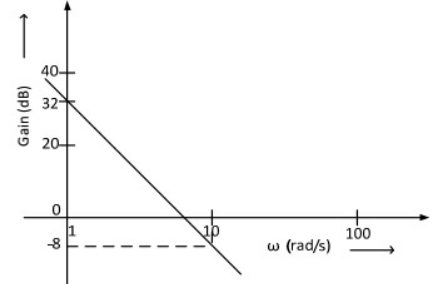 The gain (20 log|G(s)| is 32 dB and -8 dB at 1 rad/s and 10 rad/s respectively. The phase is negative for all ω. Then G(s) is (2013)
(a) 39.8/s
(b) 39.8/s2
(c) 32/s
(d) 32/s2
Ans: (b)
Sol: 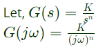 ∵ Gain = 32 dB at ω = 1 rad/sec
Q24: A system with transfer function
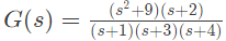 is excited by sin(ωt) . The steady-state output of the system is zero at (2012)
(a) ω = 1 rad/s
(b) ω = 2 rad/s
(c) ω = 3 rad/s
(d) ω = 4 rad/s
Ans: (c)
Sol: Fpr sinusoidal excitation,
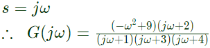 For zero steady state output
 For zero steady state output,
⇒ ω2 = 9
⇒ ω = 3rad/sec
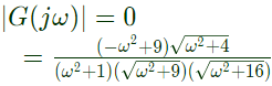
Q25: The frequency response of a linear system G(jω) is provided in the tubular form below
 Gain Margin and phase margin are (2011)
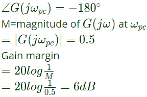
(a) 6 dB and 30°
(b) 6 dB and -30°
(c) -6 dB and 30°
(d) -6 dB and -30°
Ans: (a)
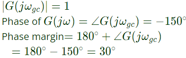
Sol: At gain crossover frequency (ωgc), magnitude of G(jω) is 1.
 At phase cross frequency (ωpc), phase of G(jω) is -180°,
Q26: The frequency response of 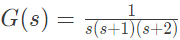 plotted in the complex G(jω) plane (for 0 < ω < ∞) is (2010)
(a) 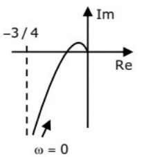 (b)
(b) 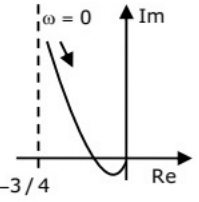 (c)
(c)  (d)
(d) 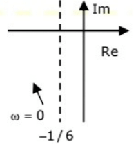 Ans: (d)
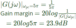
Q27: The open loop transfer function of a unity feed back system is given by G(s) = (e-0.1s)/s. The gain margin of the is system is (2009)
(a) 11.95 dB
(b) 17.67 dB
(c) 21.33 dB
(d) 23.9 dB
Ans: (d)
Sol: Open loop transfer function, 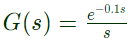
Put, s = jω
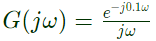 At phase crossover frequency (ωpc), phase of OLTF is -180°
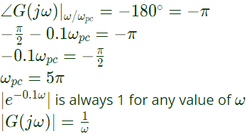 Gain at ωpc ( phase-cross frequency)
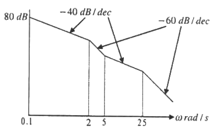
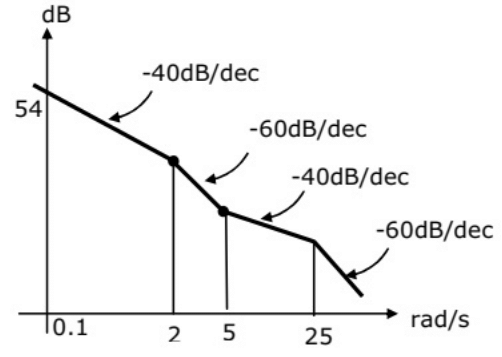
Q28: The asymptotic approximation of the log-magnitude v/s frequency plot of a system containing only real poles and zeros is shown. Its transfer function is (2009)
 (a)
(a) 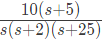
(b) 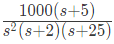
(c) 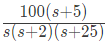
(d) 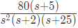
Ans: (b)
Sol: Initial slope = -40 dB/dec.
Hence the system is type-2. So the corresponding term of the transfer function is 1/s2.
At ω = 2 rad/sec, slope changes by -20 dB/dec from -40 dB/dec to -60 dB/dec. Hence the corresponding term of the transfer function is 1/(1+(s/2)).
At ω = 3 rad/sec, slope changes by 20 dB/dec from -60 dB/dec to -40 dB/dec. Hence the corresponding term of the transfer function is (1 + s/5).
At ω = 25 rad/sec, slope changes by -20 dB/dec from -40 dB/dec to -60 dB/dec. Hence the corresponding term of the transfer function is 1/(1 + s/25).
Q29: The polar plot of an open loop stable system is shown below. The closed loop system is (2009)
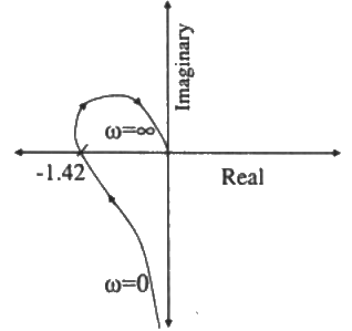 (a) always stable
(b) marginally stable
(c) unstable with one pole on the RH s-plane
(d) unstable with two poles on the RH s-plane
Ans: (d)
Sol: 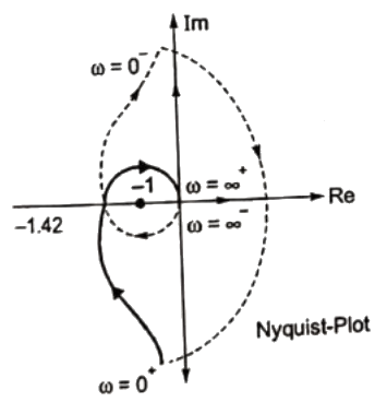 Two clockwise encirclement of 1 + j0.
N = -2
Open-loop system is stable ⇒ P = 0
N = P - Z
-2 = 0 - Z
Z = Number of closed loop poles in RHS of 8-plane. Hence the system is unstable.
Q30: The asymptotic Bode magnitude plot of a minimum phase transfer function is shown in the figure :
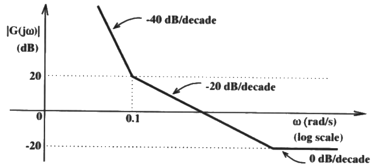 This transfer function has (2008)
(a) Three poles and one zero
(b) Two poles and one zero
(c) Two poles and two zero
(d) One pole and two zeros
Ans: (c)
Sol: Initial slope is -40 dB/decade, it means there are double pole at origin.
Slope changes from -40 dB/decade to -20 dB/decade. It means there is a zero.
Slope changes from -20 dB/decade to -0 dB/decade at some other frequency.eans ther is one more zero.
Therefore transfer function has two poles and two zeros.
Q31: If x = Re G(jω), and y = lm G(jω) then for ω → 0+, the Nyquist plot for 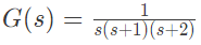 becomes asymptotic to the line (2007)
(a) x = 0
(b) x = -3/4
(c) x = y - 1/6
(d) x = y/√3
Ans: (b)
Sol: 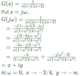
Q32: Consider the following Nyquist plots of loop transfer functions over ω = 0 to ω = ∞. Which of these plots represent a stable closed loop system ? (2006)
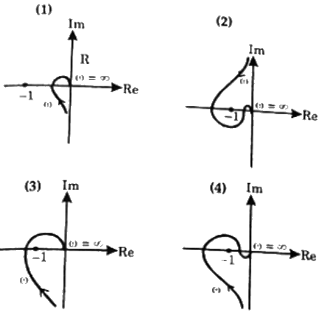 (a) (1) only
(b) All, except (1)
(c) All, except (3)
(d) (1) and (2) only
Ans: (d)
Q33: The Bode magnitude plot of
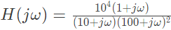 is (2006)
(a) 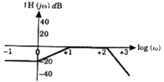 (b)
(b)  (c)
(c) 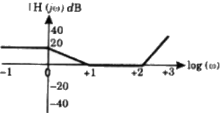 (d)
(d) 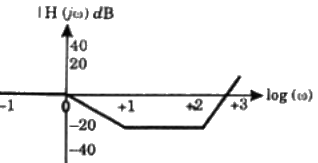 Ans: (a)
Sol: 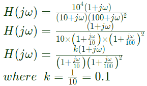 Corner frequencys
ω1 = 1 rad/sec; ω2 = 10 rad/sec and ω3 = 100 rad/sec
For frequency less than ω1 i.e. ω < ω1
Gain of the system is constant aas there is no pole at origin.
Gain = 20 logk = 20 log 0.1 = -20dB
At ω = ω1 = 1 rad/sec or ω1 = log1 = 0
There is zero, so system gain increases with slope +20dB/decades and system gain become 0 dB at ω = 10ω = 10 rad/sec or logω∣ω=10 = log10 = 1
At ω2 = 10 or logω∣ω2=10 = log10 = 1
there is pole, so slope is -20 dB/decade.
Overall slope ω2 < ω < ω3
= 20 dB/decade - 20 dB/decade
= 0 dB/decade
So, gain remain constant between
ω2 < ω < ω3
or 1 < logω < 2
At ω = ω3 = 100 rad/sec or
logω∣ω3=100 = log100 =2
the double pole are present.
So, system gain decrease with -40 dB/decade.
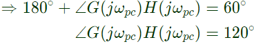
Q34: If the compensated system shown in the figure has a phase margin of 60° at the crossover frequency of 1 rad/sec, then value of the gain K is (2005)
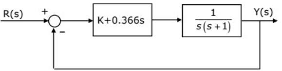 (a) 0.366
(b) 0.732
(c) 1.366
(d) 2.738
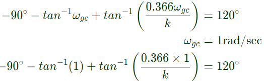
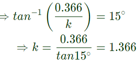
Ans: (c)
Sol: 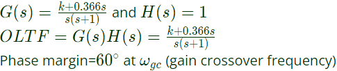
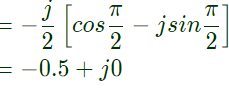
Q35: In the G(s)H(s)-plane, the Nyquist plot of the loop transfer function G(s)H(s) =  passes through the negative real axis at the point (2005)
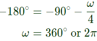
(a) (-0.25, j0)
(b) (-0.5, j0)
(c) (-1, j0)
(d) (-2, j0)
Ans: (b)
Sol: 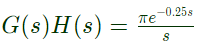 Putting s = jω, for frequency response
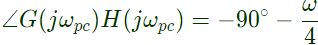
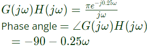 at ωpc nyquist plot cuts negative real axis and this frequency ∠G(jωpc) H(jωpc) is -180°

Q36: The gain margin of a unity feed back control system with the open loop transfer function 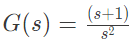 is (2005)
(a) 0
(b) 1/√2
(c) √2
(d) ∞
Ans: (d)
Sol: 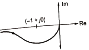 -1 + j0 is not enclosed , system is always stable.
∴ G.M. = ∞
Q37: A system with zero initial conditions has the closed loop transfer function 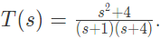 The system output is zero at the frequency (2005)
(a) 0.5 rad/sec
(b) 1 rad/sec
(c) 2 rad/sec
(d) 4 rad/sec
Ans: (c)
Sol: 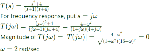 The system output is zero at 2 rad/sec.
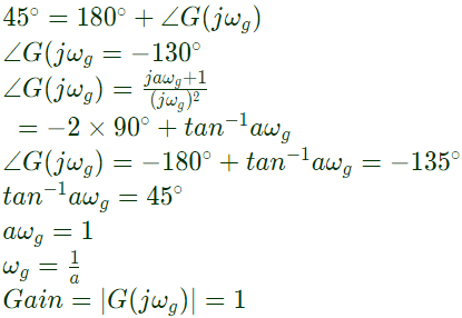
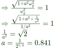
Q38: The open loop transfer function of a unity feedback control system is given as
 The value of 'a' to give a phase margin of 45° is equal to (2004)
(a) 0.141
(b) 0.441
(c) 0.841
(d) 1.141
Ans: (c)
Sol: 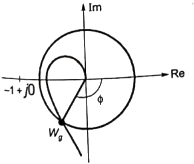
 ωg = gain crossover frequency at which open gain is loop
Phase margin = 180 +∠G(jω)
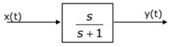
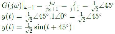
Q39: In the system shown in figure, the input x(t) = sint. In the steady-state, the response y(t) will be (2004)
 (a)
(a) 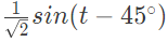
(b) 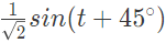
(c) sin(t - 45°)
(d) sin(t + 45°)
Ans: (b)
Sol: 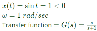 For sinusoidal input, s = jω = j
Q40: The Nyquist plot of loop transfer function G(s)H(s) of a closed loop control system passes through the point (-1, j0) in the G(s)H(s) plane. The phase margin of the system is (2004)
(a) 0°
(b) 45°
(c) 90°
(d) 180°
Ans: (a)
Sol: 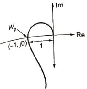 ωg is gain cross over frequency at which the gain ∣G(jω) H(jω)∣ becomes unity.
In this case, phase ∠G(jω)H(jω) is -180° at ω = ωg.
ϕ = -180°
So phase margin = 180° + ϕ = 0°
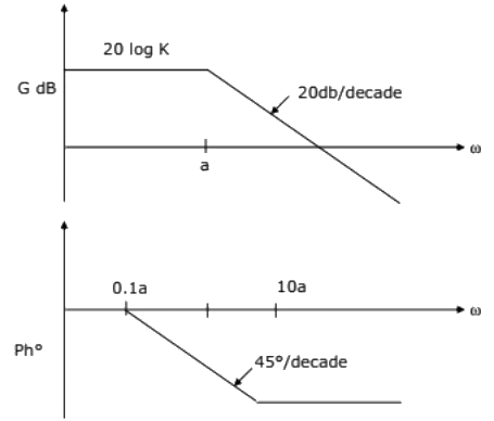
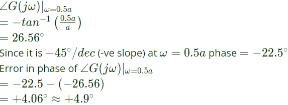
Q41: The asymptotic Bode plot of the transfer function  is given in figure. The error in phase angle and dB gain at a frequency of ω = 0.5 are respectively (2003)
 (a) 4.9°, 0.97db
(b) 5.7°, 3db
(c) 4.9°, 3db
(d) 5.7°, 0.97db
Ans: (a)
Sol: 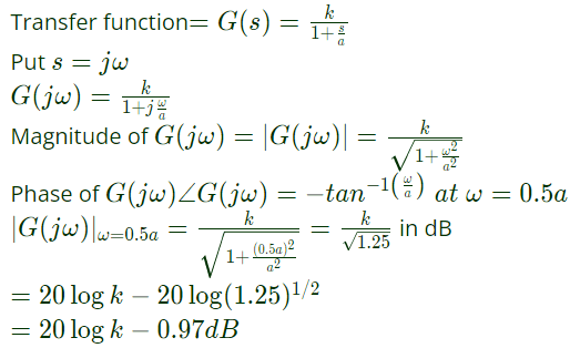 From the plot
magnitude = 20logk
∴ error in dB gain = 0.97 dB
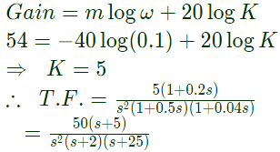
Q42: The asymptotic approximation of the log-magnitude versus frequency plot of a minimum phase system with real poles and one zero is shown in figure. Its transfer functions is (2001)
 (a)
(a) 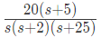
(b) 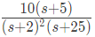
(c) 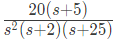
(d) 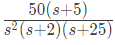
Ans: (d)
Sol: Type: 2
Poles : 0, 0, 2, 25
Zeroes : 5
Q43: The polar plot of a type-1, 3-pole, open-loop system is shown in figure. The closed loop system is (2001)
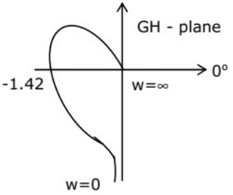 (a) always stable
(b) marginally stable
(c) unstable with one pole on the right half s-plane
(d) unstable with two poles on the right half s-plane
Ans: (d)
Sol: Nyquist plot will be
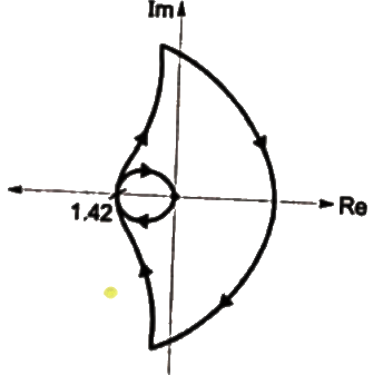 ∴ Number of encirclement of (-1, j0) = -2 and number of right sided poles in open loop system = 0
N = P-Z
∴ -2 = 0-2
⇒ Z = 2
∴ Closed loop system is unstable with two poles on the right half of s-plane.


