Previous Year Questions- A.C. Bridges | Electrical and Electronic Measurements - Electrical Engineering (EE) PDF Download
Q1: A balanced Wheatstone bridge ABCD has the following arm resistances:
RAB = 1kΩ ± 2.1 is an unknown resistance; RDA = 300Ω ± 0.4. The value of RCD and its accuracy is (2022)
(a) 30Ω ± 3Ω
(b) 30Ω ± 0.9Ω
(c) 3000Ω ± 90Ω
(d) 3000Ω ± 3Ω
Ans: (b)
Sol: The condition for balanced bridge
RABRCD = RDARBC ∴ RCD = 30 ± 30 x (3/100) = 30 ± 0.9Ω
Q2: Inductance is measured by (2021)
(a) Schering bridge
(b) Maxwell bridge
(c) Kelvin bridge
(d) Wien bridge
Ans: (b)
Sol: Maxwell's bridge is used for measurement of inductance.
Wein's bridge is used for measurement of frequency
Kelvin's bridge is used for measurement of low value of resistance.
Schering bridge is used for measurement of capacitance, dilectric loss and permittivity etc.
Q3: In the bridge circuit shown, the capacitors are loss free. At balance, the value of capacitance C1 in microfarad is ______. (SET-3 (2014))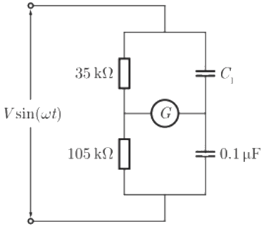 (a) 0.1
(b) 0.2
(c) 0.3
(d) 0.4
Ans: (c)
Sol: 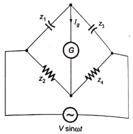 Redrawing the given bridge circuit, we have:
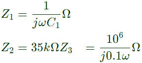 Z4 = 105 kΩ
At balance, current through galavanometer:
Ig = 0
and ∣Z1∣∣Z4∣ = ∣Z2∣∣Z3∣
 = 0.3μF
Q4: The reading of the voltmeter (rms) in volts, for the circuit shown in the figure is _________ (SET-1 (2014))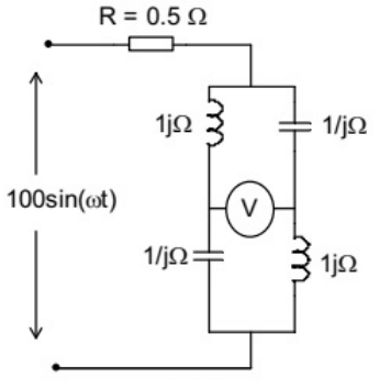 (a) 80.32
(b) 141.42
(c) 160.45
(d) 180.78
Ans: (b)
Sol: Given bridge is shown in figure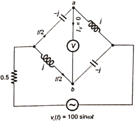 From the given bridge circuit, we see that product of opposite arm impedance are equal
i.e. (−j) × (−j) = (j)(j)
or −1 = −1
Hence, the bridge is balanced, i.e. no current flows through the voltage source V.
vi(t) = 100 sin ωt
Now, = (100/√2) Volt (rms value)
∴ Net current supplied by the source is Zeq = 0(i.e. net impedance of whole bridge = 0)
 Current flow through each parallel path of the bridge circuit, therefore V = Va − Vb
 = −jI = −j141.42 volt (rms value)
∴ Reading of the voltmeter in volt (rms)
=V = Vab = 141.42
Q5: Three moving iron type voltmeters are connected as shown below. Voltmeter readings are V, V1 and V2 as indicated. The correct relation among the voltmeter readings is (2013)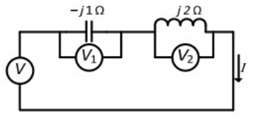 (a)
(a) 
(b) V = V1 + V2
(c) V = V1V2
(d) V = V2 − V1
Ans: (d)
Sol: V1 = -|j1Ω| x I
V2 = -|j2Ω| x I
V = -j1Ω| x I + j2Ω| x I
= V2 - V1
Q6: The bridge method commonly used for finding mutual inductance is (2012)
(a) Heaviside Campbell bridge
(b) Schering bridge
(c) De Sauty bridge
(d) Wien bridge
Ans: (a)
Sol: Heaciside Campbell bridge method is commonly used for finding mutual inductance.
Q7: A lossy capacitor Cx, rated for operation at 5 kV, 50 Hz is represented by an equivalent circuit with an ideal capacitor Cp in parallel with a resistor Rp. The value Cp is found to be 0.102 μF and value of Rp = 1.25MΩ. Then the power loss and tan δ of the lossy capacitor operating at the rated voltage, respectively, are (2011)
(a) 10 W and 0.0002
(b) 10 W and 0.0025
(c) 20 W and 0.025
(d) 20 W and 0.04
Ans: (c)
Sol: CP = 0.102 μF
RP = 1.25 MΩ
Power loss = 
= 20 W
tanδ = RIX = (1/ωCPRP) = 0.025
Q8: The bridge circuit shown in the figure below is used for the measurement of an unknown element ZX. The bridge circuit is best suited when ZX is a (2011)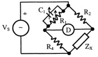 (a) low resistance
(b) high resistance
(c) low Q inductor
(d) lossy capacitor
Ans: (b)
Sol: The bridge is Maxwell bridge.
Element is an inductor.
Inductance = Lx effective resistance of the inductor = Rx The bridge is limited to measurement of low Q inductor (1 < Q < 10).
It is clear from equation (i) that the measurement of high Q coils demands a large value of resistance R1, perhaps 105 or 106Ω. The resistance boxes of such high value are very expensive. Thus for value of Q > 10, the bridge is unsuitable.
The bridge is also unsuited for coils with a very low value of Q(i.e. Q < 1).
Q9: The Maxwell's bridge shown in the figure is at balance. The parameters of the inductive coil are. (2010)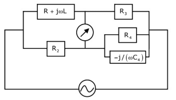 (a) R = R2R3/R4, L = C4R2R3
(b) L = R2R3/R4, R = C4R2R3
(c) R = R4/R2R3, L = C4R2R3
(d) L = R4/R2R3, R = 1/(C4R2R3)
Ans: (a)
Sol: 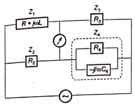 Z1 = R + jωL
Z2 = R2
Z3 = R3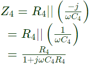 At balance,
Z1Z4 = Z2Z3 R4(R + jωL) = R2R3(1 + jωC4R4)
RR4 + jωLR4 = R2R3 + jωR2R3R4C4
Equating real and imaginary terms
RR4 = R2R3 ωLR4 = ωR2R3R4C4
L = R2R3C4
Q10: The ac bridge shown in the figure is used to measure the impedance Z.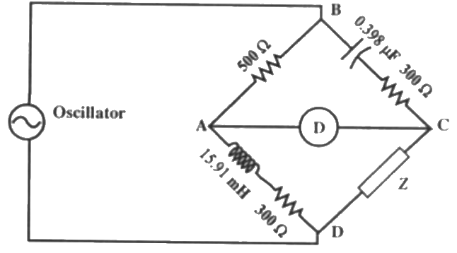 If the bridge is balanced for oscillator frequency f = 2 kHz, then the impedance Z will be (2008)
(a) (260 + j0) ω
(b) (0 + j200) ω
(c) (260 - j200) ω
(d) (260 + j200) ω
Ans: (a)
Sol: 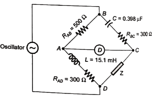 ZAB = 500Ω
ZCD = Z
ZBC = RBC + (1/jωc) ZBC = 300 − j200Ω
ZAD = RAD + jωL
ZAD = 300 + j2π × 2 × 103 × 15.91 × 10−3
= 300 + j200Ω
At balance,
ZAB × ZCD = ZBC × ZAD
ZCD = Z Z = (260 + j0)Ω
Q11: A bridge circuit is shown in the figure below. Which one of the sequence given below is most suitable for balancing the bridge? (2007)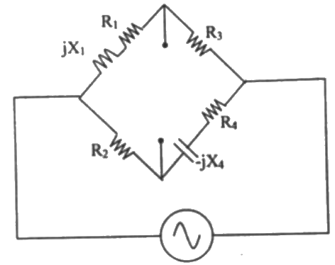 (a) First adjust R4, and then adjust R1
(b) First adjust R2, and then adjust R3
(c) First adjust R2, and then adjust R4
(d) First adjust R4, and then adjust R2
Ans: (c)
Sol:  z1 = R1 + jx1 = R1+jωL1
z2 = R2
z3 = R3
z4 = R4 − jx4 = R4 − (j/ωC4)
Under balanced condition
z1z4 = z2z3
(R1 + jωL1)(R4 − jx4) = R2R3 Equating real and imaginary terms, we obtain
 Solving above equations, we get
 Q-factor of the coil Q =
Therefore, 
 For a value of a greater than 10, the term (1/Q)2 will be smaller than 1/1000 and can be neglected. Therefore equation (i) and (ii) reduces to
L1 = R2R3C4 ...(iii)
R1 = ω2R2R3R4C24 ...(iv)
R4 appears only in equation (iv) and R2 appears in both equation (iii) and (iv).
So first R2 is adjusted and then R4 is adjusted.
Q12: The items in Group-I represent the various types of measurements to be made with a reasonable accuracy using a suitable bridge. The items in Group-II represent the various bridges available for this purpose. Select the correct choice of the item in Group-II for the corresponding item in Group-I from the following (2003) (a) P = 2, Q = 3, R = 6, S = 5
(b) P = 2, Q = 6, R = 4, S = 5
(c) P = 2, Q = 3, R = 5, S = 4
(d) P = 1, Q = 3, R = 2, S = 6
Ans: (a)
Sol: Wheat stone bridge is used for measurement of medium resistance.
Kelvin double bridge is used for meserement of low resistance.
Schering bridge is used for meserement of low value of capacitances.
Wein's bridge is used for meserement of the frequency
Hay's bridge is used for meserement of inductance of a coil with a large time-constant.
Carey-foster bridge is used for comparision of resistances which are nearly equal.
|
3 videos|39 docs|22 tests
|
FAQs on Previous Year Questions- A.C. Bridges - Electrical and Electronic Measurements - Electrical Engineering (EE)
| 1. What are the main types of A.C. bridges used in electrical engineering? |  |
| 2. How does a Maxwell Bridge work in measuring inductance? |  |
| 3. What is the significance of using A.C. instead of D.C. in bridge circuits? |  |
| 4. What are the advantages of using A.C. bridges over traditional D.C. bridges? |  |
| 5. How do you calculate the unknown component in a Schering Bridge setup? |  |
|
3 videos|39 docs|22 tests
|

|
Explore Courses for Electrical Engineering (EE) exam
|

|


