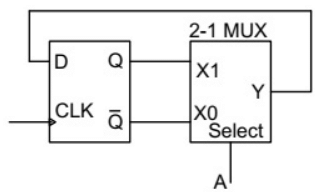
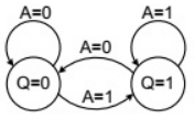
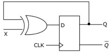
Q16: The state transition diagram for the logic circuit shown is (2012)
 (a)
(a) 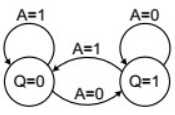 (b)
(b) 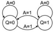 (c)
(c)
 (d)
(d) 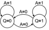 Ans: (d)
Sol: When A = 1, then Q will be selected by MUX and feedback to D flip-flop which gives output Q again.
So, at A = 1, it holds its state. When A = 0, then  will be selected by MUX and feedback to D flip-flop and output will be inverted.
Hence, for A =1, it holds the state and for A = 0, it interchange the state i.e. if Q = 0 then it will go to Q = 1 and then it will go to Q = 0.
Therefore, option (D) is correct.
Q17: Consider the given circuit
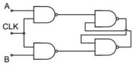 In this circuit, the race around (2012)
(a) does not occur
(b) occur when CLK = 0
(c) occur when CLK = 1 and A = B = 1
(d) occur when CLK = 1 and A = B = 0
Ans: (a)
Sol: 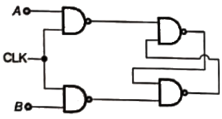 The above circuit is S-R flip-flop. The race around condition occurs in J-K flip-flop.
Q18: A two bit counter circuit is shown below
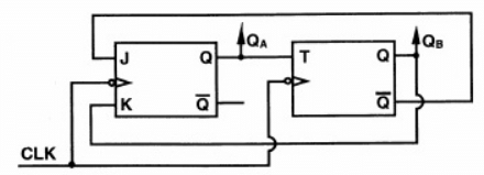 If the state QAQB of the counter at the clock time tn is '10' then the state QAQB of the counter at tn + 3 (after three clock cycles) will be (2011)
(a) 00
(b) 01
(c) 10
(d) 11
Ans: (c)
Sol: 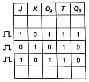 QAQB at tn + 3 is '10'
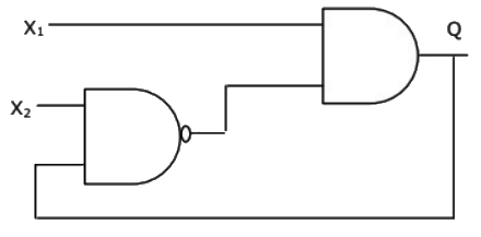
Q19: In the figure, as long as X1 = 1 and X2= 1, the output Q remains (2005)
 (a) at 1
(b) at 0
(c) at its initial value
(d) unstable
Ans: (d)
Sol: As no combination of 'Q' with (X1 and X2) = 1, output is stable.
It always switches its stable state from '1' to '0' and from '0' to '1'.
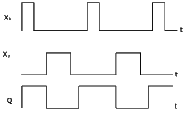
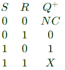
Q20: Select the circuit, which will produce the given output Q for the input signals X1 and X2 given in the figure (2005)
 (a)
(a) 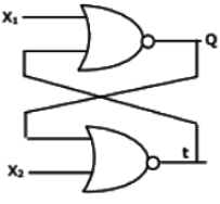 (b)
(b) 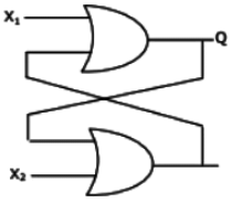 (c)
(c) 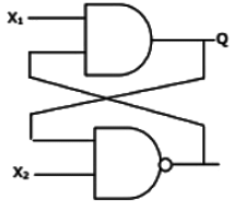 (d)
(d) 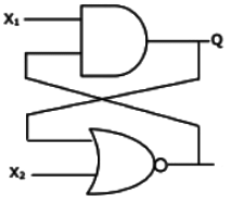 Ans: (a)
Sol: 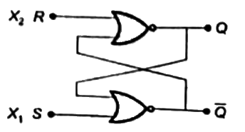
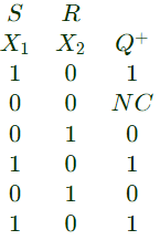 From the above table we can write,
Q21: The digital circuit shown in the figure works as (2005)
 (a) JK flip-flop
(b) Clocked RS flip-flop
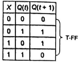
(c) T flip-flop
(d) Ring counter
Ans: (c)
Sol: Truth table of the circuit,
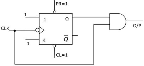
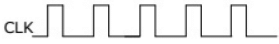
Q22: The digital circuit shown in figure generates a modified clock pulse at the output. Choose the correct output waveform from the options given below. (2004)
 (a)
(a) 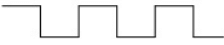 (b)
(b) 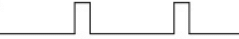 (c)
(c) 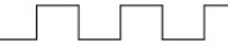 (d)
(d) 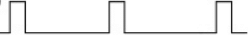 Ans: (b)
Sol: 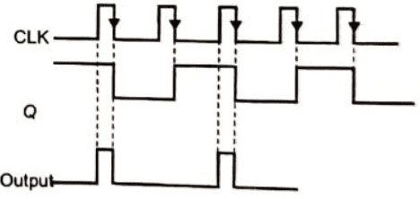
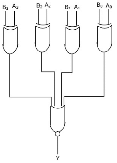
Q23: A digit circuit which compares two numbers A3A2A1A0 and B3B2B1B0 is shown in figure. To get output Y = 0, choose one pair of correct input numbers. (2004)
 (a) 1010, 1010
(b) 0101, 0101
(c) 0010, 0010
(d) 0010, 1011
Ans: (d)
Sol: For a 4-input X-NOR gate output will be zero if number of '1's will be odd.
We also knoew that output of XOR gate will be '1's if number of '1's will be odd.
If number of inputs will be same then output of XOR gate will be '0', so all input to XNOR will be zero. So, output Y will be '1'. Only in option (D) the inputs are different, so Y will be zero.
Q24: The digital circuit using two inverters shown in figure will act as (2004)
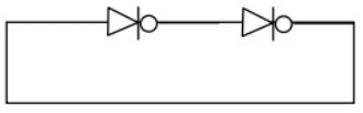 (a) a bistable multi-vibrator
(b) an astable multi-vibrator
(c) a monostable multi-vibrator
(d) an oscillator
Ans: (a)
Sol: For the both states (0, 1); our system is stable. Therefore, it is bistable multivibrator.
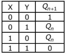
Q25: An X-Y flip-flop, whose Characteristic Table is given below is to be implemented using a J-K flip flop (2003)
 (a)
(a) 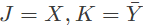
(b) 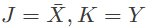
(c) 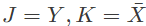
(d) 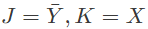
Ans: (d)
Sol: To make (X-Y) FF using (J-K) FF, (J) should be  and (K) should be (X).
Q26: The shift register shown in figure is initially loaded with the bit pattern 1010. Subsequently the shift register is clocked, and with each clock pulse the pattern gets shifted by one bit position to the right. With each shift, the bit at the serial input is pushed to the left most position (msb). After how many clock pulses will the content of the shift register become 1010 again ? (2003)
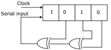 (a) 3
(a) 3
(b) 7
(c) 11
(d) 15
Ans: (b)
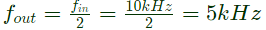
Q27: The frequency of the clock signal applied to the rising edge triggered D flip-flop shown in figure is 10 kHz. The frequency of the signal available at Q is (2002)
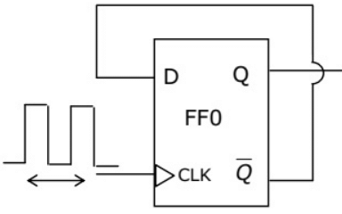 (a)10 kHz
(b) 2.5 kHz
(c) 20 kHz
(d) 5 kHz
Ans: (d)
Sol: In toggle mode