NCERT Based Activity: Electricity: Circuits and their Components


Activity 3.1: Let us explore
Take a torchlight similar to the one shown in Fig. 3.1.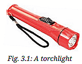
1. Observe it carefully. Do you notice a lamp? And a switch?
Ans: Yes, the torchlight has a lamp (incandescent or LED) and a switch.
2. Does the torch lamp glow (when sliding the switch)?
Ans: Yes, the torch lamp glows when the switch is slid to the "ON" position.
3. Observe the torch lamp (after sliding the switch back):
Ans: The lamp does not glow when the switch is returned to the "OFF" position.
4. What do you find inside (after opening the torchlight)?
Ans: Inside the torchlight, there are two or more electric cells.
5. Why does the torch lamp glow in one position of its switch?
Ans: The torch lamp glows when the switch is in the "ON" position because it completes the electrical circuit, allowing current to flow from the electric cells through the lamp's filament (for incandescent) or LED, causing it to glow. In the "OFF" position, the circuit is open, preventing current flow.
Activity 3.2: Let us observe
Take an electric cell, turn it around and look at it carefully (Fig. 3.2). 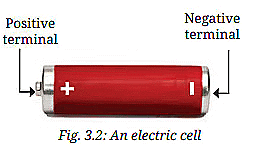
1. Do you notice a positive (+) sign and a negative (-) sign marked on the electric cell?
Ans: Yes, the electric cell has a positive (+) sign and a negative (-) sign marked on it (Fig. 3.2).
2. Do you also notice that it has a small protruding metal cap on one side and a flat metal disc on the other side?
Ans: Yes, the electric cell has a protruding metal cap (positive terminal) on one side and a flat metal disc (negative terminal) on the other side.
Explanation: This confirms that the metal cap is the positive terminal and the metal disc is the negative terminal.
Activity 3.3: Let us experiment
1. In a torch, we generally use more than one cell. Are those placed in any particular order?
Ans: Yes, the cells in a torch are placed in a specific order to form a battery.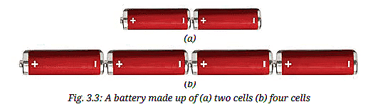
2. Take a torch which uses two cells. Open its cell compartment and take out the cells. Put the cells back in a different order. Also, try reversing the direction of one cell. Then, slide the switch and check whether the lamp glows in each case.
Check whether the lamp glows in each case (after changing cell order or reversing one cell):
Ans: When cells are placed with the positive terminal of one cell connected to the negative terminal of the next (as in Fig. 3.3), the lamp glows. If the cells are not connected in series correctly (positive to negative), the lamp does not glow.
3. Check the order in which the cells were placed in the torch when the lamp glows:
Ans: The lamp glows when the positive terminal of one cell is connected to the negative terminal of the next cell, forming a battery (Fig. 3.3).
Explanation: The specifies that a battery requires the positive terminal of one cell to connect to the negative terminal of the next for the circuit to function, allowing current to flow and the lamp to glow.
The lamp glows when the cells are placed in the order as shown in Fig. 3.3. Notice how the terminals of the two cells are connected. The positive terminal of one cell is connected to the negative terminal of the next cell. Such a combination of two or more cells is called a battery.
Activity 3.4: Let us observe
- For this activity, you will require a torchlight with an incandescent lamp (or light bulb). Many old torchlights still use such lamps. With your teacher's help, confirm that your torchlight uses an incandescent lamp. Take the torch and examine its lamp.
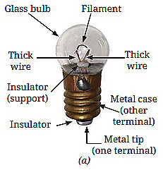
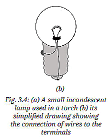
1. What do you see? Do you notice a thin wire fixed in the middle of the glass bulb?
Ans: Yes, there is a thin wire (filament) fixed in the middle of the glass bulb (Fig. 3.4a).
2. Which part of the lamp glows (when the torch is switched on)?
Ans: The thin wire (filament) inside the glass bulb glows.
3. How is the filament fixed (after inspecting the lamp)?
Ans: The filament is attached to two thicker wires that support it. One wire connects to the metal case at the lamp's base, and the other connects to the metal tip at the center of the base, forming the two terminals, fixed so they don't touch each other (Fig. 3.4b).
Explanation: This describes the incandescent lamp's structure, with the filament glowing when current passes through it, supported by two terminals.
The filament is attached to two thicker wires that support it, as shown in Fig. 3.4a. One thick wire connects to the metal case at the lamp's base, while the other connects to the metal tip at the centre of the base (Fig. 3.4b). These form the two terminals of the lamp, and are fixed in a way that they do not touch each other. In such incandescent lamps, the filament gets hot and glows to produce light.
Activity 3.5: Let us observe
- Take an LED of any colour (Fig. 3.6) and observe.
- Notice the length of two wires attached to the LED.
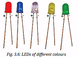
1. Do you see any filament inside it?
Ans: No, there is no filament inside the LED.
2. Do you find one of those (wires) longer than the other?
Ans: Yes, one wire (the positive terminal) is longer than the other (the negative terminal).
Explanation: Unlike incandescent lamps, LEDs have no filament and use positive (longer wire) and negative (shorter wire) terminals to conduct current in one direction.
Activity 3.6: Let us construct
- Take an electric cell, an incandescent lamp used in a torch, a cell holder, a lamp holder, and four lengths of electric wire.
- Remove about 1 cm of the plastic covering from both ends of each wire to expose the metal.
- Attach two wires to the two ends of the cell holder as shown in Fig. 3.7a.
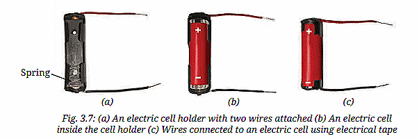
- Insert the cell in the holder such that its negative terminal is towards the spring side of the holder (Fig. 3.7b). In case a cell holder is not available, fix the two wires to the cell using electrical tape (Fig. 3.7c).
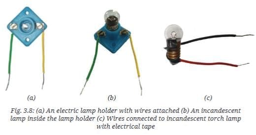
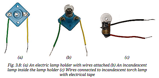
- Attach two wires to the screws of the lamp holder as shown in Fig. 3.8a. Fix the lamp in the holder by turning it around in the holder (Fig. 3.8b). In case a lamp holder is not available, use electrical tape to attach two wires to the two ends of the lamp (Fig. 3.8c).
- Now, we are ready to connect the cell to the lamp to make it glow.
- We will conduct this activity in two parts - prediction and observation. Some of the ways in which the lamp and the cell can be connected are shown in Table 3.1.
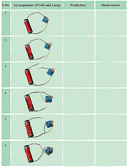
Ans: This states that the lamp glows in arrangements 1 and 6. Since Table 3.1 is not fully shown, I'll assume six arrangements are tested, with 1 and 6 being complete circuits (one terminal of the lamp connected to one terminal of the cell, and the other to the other terminal, as in Fig. 3.9). Other arrangements likely involve incomplete or incorrect connections.
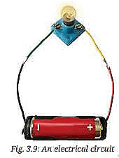 Table 3.1: Trying to make the lamp glow
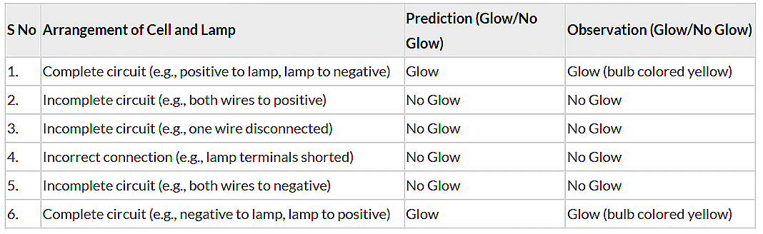
- The lamp glows only when the circuit is complete, with one terminal of the lamp connected to the positive terminal of the cell and the other to the negative terminal (Fig. 3.9).
- Arrangements 1 and 6 are complete circuits, so the lamp glows, and the bulbs are colored yellow. Other arrangements fail due to incomplete or incorrect connections.
- For incandescent lamps, the direction of connection doesn't matter.
Activity 3.7: Let us experiment
- Take two electric cells, an LED of any colour, a cell holder that can fit two cells (Fig. 3.8a), and two lengths of electric wire.
- Remove about 1 cm of the plastic covering from both ends of each wire to expose the metal.
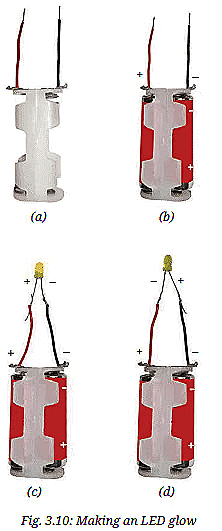
- Connect the two wires to the cell holder as shown in Fig. 3.10a.
- Insert two cells in the holder, taking care that for each cell, its negative terminal is towards the spring side of the holder (Fig. 3.10b) and the battery is ready to use.
- The terminal of the holder which is connected to the positive terminal of one cell is positive and the one connected to the negative terminal of the other cell is the negative terminal.
- Now, connect the free end of the battery positive terminal wire to the longer wire of LED, and the free end of the second wire to the shorter wire of LED (Fig. 3.10c).
- Repeat the above step but interchange the wires connected to the LED (Fig. 3.10d).
1. How will you decide which is the positive terminal of this battery?
Ans: The terminal of the holder connected to the positive terminal of one cell is the positive terminal, and the one connected to the negative terminal of the other cell is the negative terminal.
2. Does the LED glow (when positive battery terminal is connected to longer LED wire, and negative to shorter)?
Ans: Yes, the LED glows (Fig. 3.10c).
3. Does the LED glow again (after interchanging the wires)?
Ans: No, the LED does not glow (Fig. 3.10d).
Explanation: The LED glows only when its positive terminal (longer wire) is connected to the battery's positive terminal and its negative terminal (shorter wire) to the battery's negative terminal, as current flows through an LED in one direction only.
Activity 3.8: Let us construct
- Collect two drawing pins, a safety pin (or a paper clip), two wires, and a small piece of cardboard.
- Insert a drawing pin through the ring of the safety pin and fix it to the cardboard piece, ensuring that the safety pin can rotate freely (Fig. 3.11a).
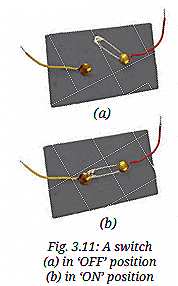
- Fix the second drawing pin to the cardboard piece so the free end of the safety pin can touch it (Fig. 3.11b).
- Connect a wire to each drawing pin-our switch is ready!
Ans: This activity involves constructing a simple switch. There are no direct questions, but the outcome is:
Result: A functional switch is created, where the safety pin can rotate to touch the second drawing pin (ON position) or not (OFF position), ready to complete or break a circuit (Fig. 3.11).
Activity 3.9: Let us test
- Connect the electric cell, lamp, and switch as shown in Fig. 3.8a.
- Rotate the free end of the safety pin till it touches the other drawing pin as shown in Fig. 3.8b.
1. Does the lamp glow (with switch in OFF position, Fig. 3.8a)?
Ans: No, the lamp does not glow because the circuit is open.
2. Does the lamp glow now (with switch in ON position, Fig. 3.8b)?
Ans: Yes, the lamp glows because the safety pin closes the circuit, allowing current to flow.
Explanation: In the OFF position, the circuit is open, preventing current flow. In the ON position, the safety pin connects both drawing pins, completing the circuit and making the lamp glow.
Activity 3.10: Let us draw
- Using symbols shown in Table 3.2, draw the circuit diagram of an electrical circuit given in Fig. 3.12a and Fig. 3.10c.
- Are your circuit diagrams similar to Fig. 3.14a and Fig. 3.14b respectively?
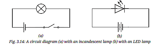
1. Draw the circuit diagram for Fig. 3.12a:
Description: Fig. 3.12a shows a circuit with an electric cell, an incandescent lamp, and a switch in the OFF position.
Circuit Diagram (based on Table 3.2 symbols):
- Electric cell: Long line (positive) and short line (negative).
- Incandescent lamp: Circle with a cross inside.
- Switch (OFF): Two dots with a gap.
- Wires: Straight lines connecting components.
- The diagram matches Fig. 3.14a, with the cell connected to the lamp and switch, but the switch open.
2. Draw the circuit diagram for Fig. 3.10c:
Description: Fig. 3.10c shows a circuit with a battery (two cells), an LED, and wires, with the LED's positive terminal (longer wire) connected to the battery's positive terminal.
Circuit Diagram (based on Table 3.2 symbols):
- Battery: Two cells, each with long (positive) and short (negative) lines, connected positive-to-negative.
- LED: Triangle with two arrows, pointing to the negative side.
- Wires: Straight lines connecting battery positive to LED positive, and LED negative to battery negative.
- The diagram matches Fig. 3.14b, showing a closed circuit with the LED oriented correctly.
3. Are your circuit diagrams similar to Fig. 3.14a and Fig. 3.14b respectively?
Ans: Yes, the drawn diagrams are similar to Fig. 3.14a (incandescent lamp circuit with switch OFF) and Fig. 3.14b (LED circuit with correct polarity).
Explanation: Table 3.2 provides symbols for components. Fig. 3.14a and 3.14b are standard circuit diagrams, and the descriptions above align with the physical setups in Fig. 3.12a and Fig. 3.10c .
Activity 3.11: Let us identify
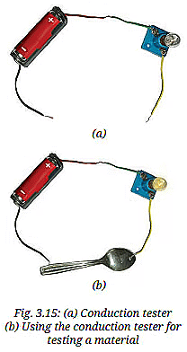
- Connect an electric cell and a lamp while leaving the two ends of wires free as shown in Fig. 3.15a.
- Touch the two free ends of the wires momentarily. Does the lamp glow? If yes, our tester is ready. We can use this tester to identify the materials through which electric current passes.
- Collect objects of different materials, such as metal spoons, coins, cork, rubber, glass, keys, pins, plastic scale, wooden block, aluminium foil, candle, sewing needle, cardboard, paper, and pencil lead.
- One by one, touch the free ends of the tester's wires to both ends of each object you have tested (Fig. 3.15b). Make sure the wires don't touch each other. Does the lamp glow every time?
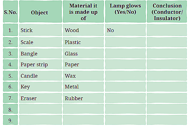
- Record your observations in Table 3.3.
- Analyse your observations. Did the lamp glow for all materials?
- Based on the observations you have recorded in Table 3.3, conclude which materials are conductors of electricity and which are insulators. Note it in Table 3.3.
1. Does the lamp glow (when touching the free ends of the wires)?
Ans: Yes, the lamp glows, confirming the tester is ready.
2. Does the lamp glow every time (for each object)?
Ans: No, the lamp glows only for some materials.
3. Table 3.3: Identifying Conductors and Insulators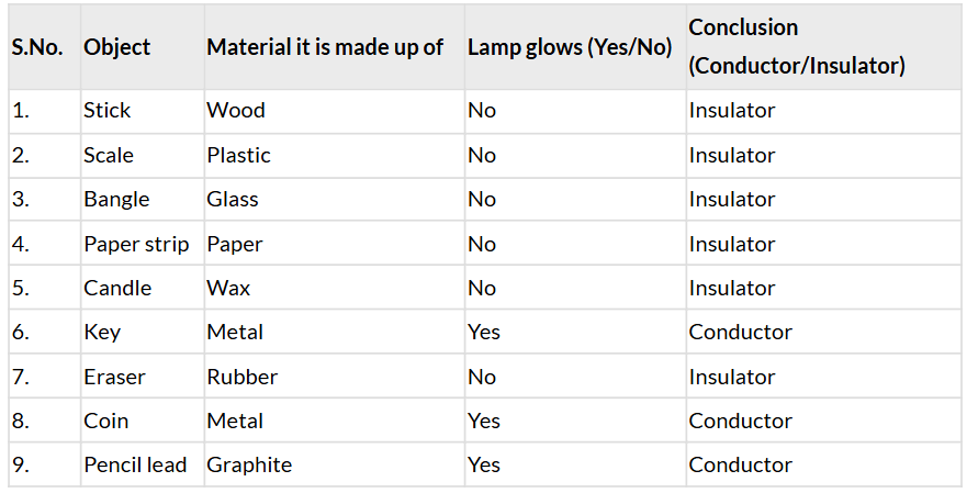
- Metal spoon: Metal, Yes, Conductor
- Cork: Cork, No, Insulator
- Pins: Metal, Yes, Conductor
- Wooden block: Wood, No, Insulator
- Aluminium foil: Metal, Yes, Conductor
- Sewing needle: Metal, Yes, Conductor
- Cardboard: Cardboard, No, Insulator
4. Analyse your observations. Did the lamp glow for all materials?
Ans: No, the lamp glowed only for metals (e.g., key, coin, pins, aluminium foil, sewing needle) and graphite (pencil lead), but not for wood, plastic, glass, paper, wax, rubber, cork, or cardboard.
5. Conclude which materials are conductors of electricity and which are insulators:
- Conductors: Metal (spoon, coin, key, pins, aluminium foil, sewing needle), Graphite (pencil lead).
- Insulators: Wood (stick, wooden block), Plastic (scale), Glass (bangle), Paper (paper strip, cardboard), Wax (candle), Rubber (eraser), Cork.
Explanation: Conductors (metals, graphite) allow electric current to flow, making the lamp glow. Insulators (wood, plastic, glass, etc.) prevent current flow, so the lamp doesn't glow . Graphite, though not a metal, is a conductor due to its carbon structure.
FAQs on NCERT Based Activity: Electricity: Circuits and their Components
| 1. What are the basic components of an electric circuit? |  |
| 2. How does a circuit work? | |
| 3. What is the difference between series and parallel circuits? | |
| 4. Why is it important to use a switch in an electric circuit? | |
| 5. What safety precautions should be taken while working with electrical circuits? | |