HC Verma Summary: Rotational Motion - 1


Rotational Mechanics
Consider a pulley fixed at a typical Indian well on which a rope is wound with one end attached to a bucket. When the bucket is released, the pulley starts rotating. As the bucket goes down, the pulley rotates more rapidly till the bucket goes into the water.
Take the pulley as the system. The centre of mass of the pulley is at its geometrical centre which remains at rest. However, the other particles of the pulley move and are accelerated. The pulley is said to be executing rotational motion. Also, the rotational motion is not uniform. Since σCM = 0, the resultant external force F acting on the pulley must be zero. Even then the pulley is not in rotational equilibrium. We shall now study this type of motion.
Rotation of a Rigid Body About a Given Fixed Line
Take a rigid body like a plate or a ball or your tennis racket or anything else present nearby and hold it between your fingers at two points. Now keep these two points fixed and then displace the body (try it with any rigid body at hand).
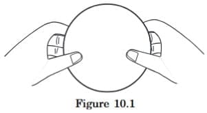
Notice the kind of displacement you can produce. In particular, notice that each particle of the rigid body goes in a circle, the centre being on the line joining the two fixed points between your finger tips. Let us call this line the axis of rotation. In fact, the centre of the circular path of a particle is at the foot of the perpendicular from the particle to this axis. Different particles move in different circles, the planes of all these circles are parallel to each other, and the radii depend on the distances of the particles from this axis. The particles on the axis remain stationary, those close to this line move on smaller circles and those far away from this line move in larger circles. However, each particle takes equal time to complete its circle.
Such a displacement of a rigid body in which a given line is held fixed, is called rotation of the rigid body about the given line. The line itself is called the axis of rotation.
Examples:
(1) Consider the door of your almirah. When you open the door, the vertical line passing through the hinges is held fixed and that is the axis of rotation. Each point of the door describes a circle with the centre at the foot of the perpendicular from the particle on the axis. All these circles are horizontal and thus perpendicular to the axis.
(2) Consider the ceiling fan in your room. When it is on, each point on its body goes in a circle. Locate the centres of the circles traced by different particles on the three blades of the fan and the body covering the motor. All these centres lie on a vertical line through the centre of the body. The fan rotates about this vertical line.
(3) Look at the on-off switch on the front panel of your gas stove in the kitchen. To put the gas on, you push the switch a little, and then you rotate it. While rotating, each particle of the switch moves on a circle. Think about the centres of all such circles. They lie on a straight line (generally horizontal, towards the operator). This is the axis of rotation and the switch rotates about this axis.
Sometimes the axis may not pass through the body. Consider a record rotating on the turntable of a record player. Suppose a fly is sitting on the record near the rim. Look at the path of any particle of the fly. It is a circle with the centre on the vertical line through the centre of the record. The fly is "rotating about this vertical line" (can you consider the fly as a rigid body?). The axis of rotation is lying completely outside the fly.
If each particle of a rigid body moves in a circle, with centres of all the circles on a straight line and with planes of the circles perpendicular to this line, we say that the body is rotating about this line. The straight line itself is called the axis of rotation.
Kinematics
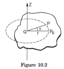
Consider a rigid body rotating about a given fixed line. Take this line as the Z-axis. Consider a particle P of the body (figure 10.2). Look at its position P0 at t = 0. Draw a perpendicular P0Q to the axis of rotation. At time t, the particle moves to P. Let ∠ P0QP0 = θ. We say that the particle P has rotated through an angle θ. In fact, all the particles of the body have also rotated through the same angle θ and so we say that the whole rigid body has rotated through an angle θ. The "angular position" of the body at time t is said to be θ. If P has made a complete revolution on its circle, every particle has done so and we say that the body has rotated through an angle of 2π. So the rotation of a rigid body is measured by the rotation of the line QP from its initial position.
Now, suppose the angular position of the body at time t is θ. During a time Δt, it further rotates through Δθ, so that its angular position becomes θ + Δθ. The average angular velocity during the time interval Δt is ω = Δθ / Δt.
The instantaneous angular velocity at time t is ω = dθ/dt.
We associate the direction of the axis of rotation with the angular velocity. If the body rotates anticlockwise as seen through the axis, the angular velocity is towards the viewer. If it rotates clockwise, the angular velocity is away from the reader. It turns out that the angular velocity adds like a vector and hence it becomes a vector quantity. The magnitude of angular velocity is called angular speed. However, we shall continue to use the word angular velocity if the direction of the axis is clear from the context. The SI unit for angular velocity is radian/sec (rad/s). Quite often the angular velocity is given in revolutions per second (rev/s). The conversion in radian per second may be made using 1 rev = 2π radian.
If the body rotates through equal angles in equal time intervals (irrespective of the smallness of the intervals), we say that it rotates with uniform angular velocity. In this case ω = dθ/dt = constant and thus θ = ω t. If it is not the case, the body is said to be rotationally "accelerated". The angular acceleration is defined as
α = dω/dt = d/dt (dθ/dt) = d²θ/dt².
If the angular acceleration α is constant, we have
ω = ω0 + α t (10.1)
θ = ω0 t + (1/2) α t² (10.2)
ω² = ω0² + 2αθ (10.3)
where ω0 is the angular velocity of the body at t = 0.
As an example, think of your ceiling fan. Switch on the fan. The fan rotates about a vertical line (axis). The angle rotated by the fan in the first second is small, that in the second second is larger, that in the third second is still larger and so on. The fan, thus, has an angular acceleration. The angular velocity ω = dθ/dt increases with time. Wait for about a couple of minutes. The fan has now attained full speed. The angle rotated in any time interval is now equal to the angle rotated in the successive equal time interval. The fan is rotating uniformly about the vertical axis. Now switch off the fan. The angle rotated in any second is smaller than the angle rotated in the previous second. The angular velocity dω/dt decreases as time passes, and finally it becomes zero when the fan stops. The fan has an angular deceleration.
Given the axis of rotation, the body can rotate in two directions. Looking through the axis, it may be clockwise or anticlockwise. One has to define the "positive" rotation. This may be defined according to the convenience of the problem, but once decided, one has to stick to the choice. The angular displacement, angular velocity and the angular acceleration may accordingly be positive or negative.
Notice the similarity between the motion of a particle on a straight line and the rotation of a rigid body about a fixed axis. The position of the particle was decided by a single variable x, which could be positive or negative according to the choice of the positive direction of the X-axis. The rate of change of position gave the velocity and the rate of change of velocity gave the acceleration.
Example 10.1: The motor of an engine is rotating about its axis with an angular velocity of 100 rev/minute. It comes to rest in 15 s, after being switched off. Assuming constant angular deceleration, calculate the number of revolutions made by it before coming to rest.
Solution: The initial angular velocity = 100 rev/minute = (10 π/3) rad/s.
Final angular velocity = 0.
Time interval = 15 s.
Let the angular acceleration be α. Using the equation ω = ω0 + αt, we obtain α = (-2π/9) rad/s².
The angle rotated by the motor during this motion is
θ = ω0 t + (1/2) α t²
= ((10π rad)/(3 s)) (15 s) - (1/2) ((2π rad)/(9 s²)) (15 s)²
= 25π rad = 12.5 revolutions.
Hence the motor rotates through 12.5 revolutions before coming to rest.
Example 10.2: Starting from rest, a fan takes five seconds to attain the maximum speed of 400 rpm(revolutions per minute). Assuming constant acceleration, find the time taken by the fan in attaining half the maximum speed.
Solution: Let the angular acceleration be α. According to the question,
400 rev/min = 0 + α · 5 s (i)
Let t be the time taken in attaining the speed of 200 rev/min which is half the maximum.
200 rev/min = 0 + αt (ii)
Dividing (i) by (ii), we get,
2 = 5 s/t or, t = 2.5 s.
Relation Between the Linear Motion of a Particle of a Rigid Body and its Rotation
Consider a point P of the rigid body rotating about a fixed axis as shown in figure (10.2). As the body rotates, this point moves on a circle. The radius of this circle is the perpendicular distance of the particle from the axis of rotation. Let it be r. If the body rotates through an angle θ, so does the radius joining the particle with the centre of its circle. The linear distance moved by the particle is s = rθ along the circle.
The linear speed along the tangent is
v = ds/dt = r · dθ/dt = rω (10.4)
and the linear acceleration along the tangent, i.e., the tangential acceleration, is
a = dv/dt = r · dω/dt = rα. (10.5)
The relations v = rω and a = rα are very useful and their meanings should be clearly understood. For different particles of the rigid body, the radius r of their circles has different values, but ω and α are same for all the particles. Thus, the linear speed and the tangential acceleration of different particles are different. For r = 0, i.e., for the particles on the axis, v = rω = 0 and a = rα = 0, consistent with the fact that the particles on the axis do not move at all.
Example 10.3: A bucket is being lowered down into a well through a rope passing over a fixed pulley of radius 10 cm. Assume that the rope does not slip on the pulley. Find the angular velocity and angular acceleration of the pulley at an instant when the bucket is going down at a speed of 20 cm/s and has an acceleration of 4.0 m/s².
Solution: Since the rope does not slip on the pulley, the linear speed v of the rim of the pulley is same as the speed of the bucket.
The angular velocity of the pulley is then
ω = v / r = (20 cm/s) / (10 cm) = 2 rad/s
and the angular acceleration of the pulley is
α = a / r = (4.0 m/s²) / (10 cm) = 40 rad/s².
Rotational Dynamics
When one switches a fan on, the centre of the fan remains unmoved while the fan rotates with an angular acceleration. As the centre of mass remains at rest, the external forces acting on the fan must add to zero. This means that one can have angular acceleration even if the resultant external force is zero. But then why do we need to switch on the fan in order to start it? If an angular acceleration may be achieved with zero total external force, why does not a wheel chair start rotating on the floor as soon as one wishes it to do so. Why are we compelled to use our muscles to set it into rotation? In fact, one cannot have angular acceleration without external forces.
What is then the relation between the force and the angular acceleration? We find that even if the resultant external force is zero, we may have angular acceleration. We also find that without applying an external force we cannot have an angular acceleration. What is responsible for producing angular acceleration? The answer is torque which we define below.
Torque of a Force about the Axis of Rotation
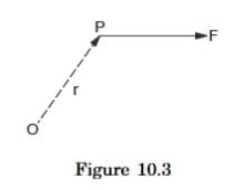
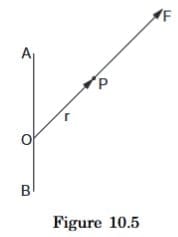
Consider a force F acting on a particle P. Choose an origin O and let r be the position vector of the particle experiencing the force. We define the torque of the force F about O as
Γ = r × F (10.6)
This is a vector quantity having its direction perpendicular to r and F according to the rule of cross product. Now consider a rigid body rotating about a given axis of rotation AB (figure 10.4). Let F be a force acting on the particle P of the body. F may not be in the plane ABP. Take the origin O somewhere on the axis of rotation.
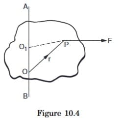
The torque of F about O is Γ = r × F. Its component along OA is called the torque of F about OA. To calculate it, we should find the vector r × F and then find out the angle θ, it makes with OA. The torque about OA is then |r × F| cos θ. The torque of a force about a line is independent of the choice of the origin as long as it is chosen on the line. This can be shown as given below. Let O1 be any point on the line AB (figure 10.4). The torque of F about O1 is
O1P × F = (O1O + OP) × F = O1O × F + OP × F.
As O1O × F ⊥ O1O, this term will have no component along AB.
Thus, the component of O1P × F is equal to that of OP × F.
There are some special cases which occur frequently.
Case I
F ⊥ AB.
r × F is perpendicular to F, but F ⊥ AB, hence r × F is perpendicular to AB. The component of r × F along AB is, therefore, zero.
Case II
F intersects AB (say at O)
Taking the point of intersection as the origin, we see that r = OP and F are in the same line. The torque about O is r × F = 0. Hence the component along OA is zero.
Case III
F ⊥ AB but F and AB do not intersect.
In three dimensions, two lines may be perpendicular without intersecting each other. For example, a vertical line on the surface of a wall of your room and a horizontal line on the opposite wall are mutually perpendicular but they never intersect. Two nonparallel and nonintersecting lines are called skew lines.
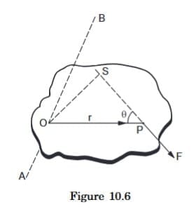
Figure (10.6) shows the plane through the particle P that is perpendicular to the axis of rotation AB. Suppose the plane intersects the axis at the point O. The force F is in this plane. Taking the origin at O,
Γ = r × F - OP × F.
Thus, Γ = F.(OS).
where OS is the perpendicular from O to the line of action of the force F. The line OS is also perpendicular to the axis of rotation. It is thus the length of the common perpendicular to the force and the axis of rotation.
The direction of Γ = O F × F is along the axis AB because AB ⊥ OP and AB ⊥ R. The torque about AB is, therefore, equal to the magnitude of Γ that is F.(OS).
Thus, the torque of F about AB = magnitude of the force F × length of the common perpendicular to the force and the axis. The common perpendicular OS is called the lever arm or moment arm of this torque.
The torque may try to rotate the body clockwise or anticlockwise about AB. Depending on the convenience of the problem one may be called positive and the other negative. It is conventional to take the torque positive if the body rotates anticlockwise as viewed through the axis.
Case IV
- F and OA are skew but not perpendicular.
- Take components of F parallel and perpendicular to the axis.
- The torque of the parallel part is zero from case I and that of the perpendicular part may be found as in case III.
- In most of the applications that we shall see, cases I, II or III will apply.
Example 10.4: Consider a pulley fixed at its centre of mass by a clamp. A light rope is wound over it and the free end is tied to a block. The tension in the rope is T. (a) Write the forces acting on the pulley. How are they related? (b) Locate the axis of rotation. (c) Find the torque of the forces about the axis of rotation.
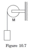
Solution: (a) The forces on the pulley are (figure 10.7)
(i) attraction by the earth, Mg vertically downward,
(ii) tension T by the rope, along the rope,
(iii) contact force N by the support at the centre.
N = T + Mg (centre of mass of the pulley is at rest, so Newton's 1st law applies).
(b) The axis of rotation is the line through the centre of the pulley and perpendicular to the plane of the pulley.
(c) Let us take the positive direction of the axis towards the reader.
The force Mg passes through the centre of mass and it intersects the axis of rotation. Hence the torque of Mg about the axis is zero (Case II). Similarly, the torque of the contact force N is also zero.
The tension T is along the tangent of the rim in the vertically downward direction. The tension and the axis of rotation are perpendicular but never intersect. Case III applies. Join the point where the rope leaves the rim to the centre. This line is the common perpendicular to the tension and the axis. Hence the torque is T.r (positive, since it will try to rotate the pulley anticlockwise).
If there are more than one forces F1, F2, F3, ... acting on a body, one can define the total torque acting on the body about a given line.
To obtain the total torque, we have to get separately the torques of the individual forces and then add them.
Γ = r1 × F1 + r2 × F2 + ...
You may be tempted to add the forces F1, F2, F3, ... vectorially and then obtain the torque of resultant force about the axis. But that won't always work. Even if F1 + F2 + ... = 0, r1 × F1 + r2 × F2 + ... may not. However, if the forces act on the same particle, one can add the forces and then take the torque of the resultant.
10.5 Γ = Iα
We are now in a position to tell how the angular acceleration is produced when the resultant force on the body is zero. It is the total torque that decides the angular acceleration. Although the resultant force on the fan in our example is zero, the total torque is not. Whereas, if one does not apply any force, the torque is also zero and no angular acceleration is produced. For angular acceleration, there must be a torque.
To have linear acceleration of a particle, the total force on the particle should be nonzero. The acceleration of the particle is proportional to the force applied on it. To have angular acceleration about an axis you must have a nonzero torque on the body about the axis of rotation. Do we also have the relation that the angular acceleration is proportional to the total torque on the body? Let us hope so.
Consider a rigid body rotating about a fixed axis AB (Figure 10.8). Consider a particle P of mass m rotating in a circle of radius r.
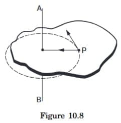
The radial acceleration of the particle is v² / r = ω² r.
Thus, the radial force on it = mω² r.
The tangential acceleration of the particle is dv/dt.
Thus, the tangential force on it
= m dv/dt = m r dω/dt = m r α.
The torque of mω² r about AB is zero as it intersects the axis and that of mrα is mr²α as the force and the axis are skew and perpendicular. Thus, the torque of the resultant force acting on P is mr²α. Summing over all the particles, the total torque of all the forces acting on all the particles of the body is
Γtotal = ∑i mi ri² α = Iα (i)
where
I = ∑i mi ri². (10.7)
The quantity I is called the moment of inertia of the body about the axis of rotation. Note that mi is the mass of the ith particle and ri is its perpendicular distance from the axis.
We have Γtotal = ∑i (ri × Fi) where Fi is the resultant force on the ith particle. This resultant force consists of forces by all the other particles as well as other external forces applied on the ith particle. Thus,
Γtotal = ∑i ri × (∑j ≠ i Fij + Fiext)
where Fij is the force on the ith particle by the jth particle and Fiext is the external force applied on the ith particle. When summation is made on both i and j, the first summation contains pairs like ri × Fij + rj × Fji. Newton's third law tells us that Fij = -Fji so that such pairs become (ri - rj) × Fij. Also the force Fij is along the line joining the particles so that (ri - rj) ∥ Fij and the cross product is zero. Thus, it is necessary to consider only the torques of the external forces applied on the rigid body and (i) becomes
Γext = Iα (10.8)
where the torque and the moment of inertia are both evaluated about the axis of rotation.
Note the similarity between Γ = Iα and F = Ma. Also, note the dissimilarity between the behaviour of M and I. The mass M is a property of the body and does not depend on the choice of the origin or the axes or the kind of motion it undergoes (as long as we are dealing with velocities much less than 3 × 10⁸ m/s). But the moment of inertia I = ∑i mi ri² depends on the choice of the axis about which it is calculated. The quantity ri is the perpendicular distance of the ith particle from the "axis". Changing the axis changes ri and hence I.
Moment of inertia of bodies of simple geometrical shapes may be calculated using the techniques of integration. We shall discuss the calculation for bodies of different shapes in somewhat greater detail in a later section.
Note that Γ = Iα is not an independent rule of nature. It is derived from the more basic Newton's laws of motion.
Example 10.5: A wheel of moment of inertia I and radius r is free to rotate about its centre as shown in figure (10.9). A string is wrapped over its rim and is pulled by a force of 5.0 N. It is found that the torque produces an angular acceleration 2.0 rad/s² in the wheel. Calculate the moment of inertia of the wheel.
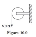
Solution: The forces acting on the wheel are (i) W due to gravity, (ii) N due to the support at the centre and (iii) F due to tension. The torque of W and N are separately zero and that of F is F.r. The net torque is
Γ = (5.0 N).(10 cm) = 0.50 N-m.
The moment of inertia is
I = Γ / α = (0.50 N-m) / (2 rad/s²) = 0.25 kg-m².
Bodies in Equilibrium
The centre of mass of a body remains in equilibrium if the total external force acting on the body is zero. This follows from the equation F = Ma. Similarly, a body remains in rotational equilibrium if the total external torque acting on the body is zero. This follows from the equation Γ = Iα. Thus, if a body remains at rest in an inertial frame, the total external force acting on the body should be zero in any direction and the total external torque should be zero about any line.
We shall often find situations in which all the forces acting on a body lie in a single plane as shown in figure (10.10).
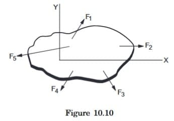
Let us take this plane as the X-Y plane. For translational equilibrium
∑ Fx = 0 (i)
∑ Fy = 0. (ii)
As all the forces are in the X-Y plane, Fz is identically zero for each force and so ∑ Fz = 0 is automatically satisfied. Now consider rotational equilibrium. The torque of each force about the X-axis is identically zero because either the force intersects the axis or it is parallel to it. Similarly, the torque of each force about the Y-axis is identically zero. In fact, the torque about any line in the X-Y plane is zero.
Thus, the condition for rotational equilibrium is
∑ Γz = 0. (iii)
While taking torque about the Z-axis, the origin can be chosen at any point in the plane of the forces. That is, the torque can be taken about any line perpendicular to the plane of the forces. In general, the torque is different about different lines but it can be shown that if the resultant force is zero, the total torque about any line perpendicular to the plane of the forces is equal. If it is zero about one such line, it will be zero about all such lines.
If a body is placed on a horizontal surface, the torque of the contact forces about the centre of mass should be zero to maintain the equilibrium. This may happen only if the vertical line through the centre of mass cuts the base surface at a point within the contact area or the area bounded by the contact points. That is why a person leans in the opposite direction when he or she lifts a heavy load in one hand.
The equilibrium of a body is called stable if the body tries to regain its equilibrium position after being slightly displaced and released. It is called unstable if it gets further displaced after being slightly displaced and released. If it can stay in equilibrium even after being slightly displaced and released, it is said to be in neutral equilibrium.
In the case of stable equilibrium, the centre of mass goes higher on being slightly displaced. For unstable equilibrium it goes lower and for neutral equilibrium it stays at the same height.
Bending of a Cyclist On a Horizontal Turn
Suppose a cyclist is going at a speed v on a circular horizontal road of radius r which is not banked. Consider the cycle and the rider together as the system. The centre of mass C (figure 10.11a) of the system is going in a circle with the centre at O and radius r.
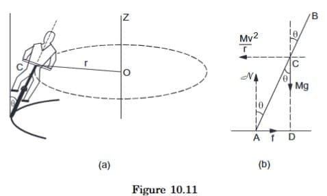
Let us choose O as the origin, OC as the X-axis and vertically upward as the Z-axis. This frame is rotating at an angular speed ω = v/r about the Z-axis. In this frame the system is at rest. Since we are working from a rotating frame of reference, we will have to apply a centrifugal force on each particle. The net centrifugal force on the system will be Mω² r = Mv²/r, where M is the total mass of the system. This force will act through the centre of mass. Since the system is at rest in this frame, no other pseudo force is needed.
Figure (10.11b) shows the forces. The cycle is bent at an angle θ with the vertical. The forces are
(i) weight Mg,
(ii) normal force N,
(iii) friction f and,
(iv) centrifugal force Mv²/r.
In the frame considered, the system is at rest. Thus, the total external force and the total external torque must be zero. Let us consider the torques of all the forces about the point A. The torques of N and f about A are zero because these forces pass through A. The torque of Mg about A is Mg(AD) in the clockwise direction and that of N is N (CD) in the anti-clockwise direction. For rotational equilibrium,
Mg(AD) = (Mv² / r) (CD)
or, AD / CD = v² / rg
or, tanθ = v² / rg (10.9)
Thus the cyclist bends at an angle tan⁻¹(v² / rg) with the vertical.
Angular Momentum
Angular momentum of a particle about a point O is defined as
l = r × p (10.10)
where p is the linear momentum and r is the position vector of the particle from the given point O. The angular momentum of a system of particles is the vector sum of the angular momenta of the particles of the system. Thus,
L = ∑ li = ∑ (ri × pi).
Suppose a particle is going in a circle of radius r and at some instant the speed of the particle is v (figure 10.12). Its angular momentum about the axis of the circle?
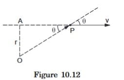
As the origin may be chosen anywhere on the axis, we choose it at the centre of the circle. Then r is along a radius and v is along the tangent so that r is perpendicular to v and l = |r × p| = mvr. Also r × p is perpendicular to r and p and hence is along the axis. Thus, the component of r × p along the axis is mvr itself.
Next consider a rigid body rotating about an axis AB (figure 10.13b). Let the angular velocity of the body be ω. Consider the i th particle going in a circle of radius ri with its plane perpendicular to AB. The linear velocity of this particle at this instant is vi = riω. The angular momentum of this particle about AB is mi vi ri = mi ri² ω. The angular momentum of the whole body about AB is the sum of these components, i.e.,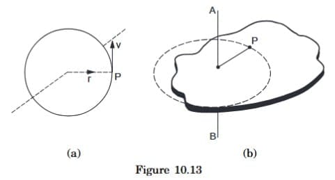
L = ∑ mi ri² ω = Iω (10.12)
where I is the moment of inertia of the body about AB.
Conservation of Angular Momentum
We have defined the angular momentum of a body as L = ∑ (ri × pi). Differentiating with respect to time,
dL/dt = d/dt ∑ (ri × pi)
= ∑ [ dri/dt × pi + ri × dpi/dt ]
= ∑ [ vi × m vi + ri × Fi ]
= ∑ (ri × Fi) = Γtotal (i)
where Fi is the total force acting on the ith particle. This includes any external force as well as the forces on the ith particle by all the other particles. When summation is taken over all the particles, the internal torques add to zero. Thus, (i) becomes
dL/dt = Γext (10.13)
where Γext is the total torque on the system due to all the external forces acting on the system.
For a rigid body rotating about a fixed axis, we can arrive at equation (10.13) in a simpler manner. We have
L = Iω
or, dL/dt = I dω/dt = Iα
or, dL/dt = Γext.
Equation (10.13) shows that
If the total external torque on a system is zero, its angular momentum remains constant.
This is known as the principle of conservation of angular momentum.
Example 10.6: A wheel is rotating at an angular speed ω about its axis which is kept vertical. An identical wheel initially at rest is gently dropped into the same axle and the two wheels start rotating with a common angular speed. Find this common angular speed.
Solution: Let the moment of inertia of the wheel about the axis be I. Initially the first wheel is rotating at the angular speed ω about the axle and the second wheel is at rest. Take both the wheels together as the system. The total angular momentum of the system before the coupling is Iω + 0 = Iω. When the second wheel is dropped into the axle, the two wheels slip on each other and exert forces of friction. The forces of friction have torques about the axis of rotation but these are torques of internal forces. No external torque is applied on the two-wheel system and hence the angular momentum of the system remains unchanged. If the common angular speed is ω', the total angular momentum of the two-wheel system is 2Iω' after the coupling. Thus,
Iω = 2Iω'
or, ω' = ω/2.
FAQs on HC Verma Summary: Rotational Motion - 1
| 1. What is the significance of torque in rotational dynamics? |  |
| 2. How does angular momentum differ from linear momentum? | |
| 3. What role does angular impulse play in changing angular momentum? | |
| 4. Why is the concept of bodies in equilibrium important in rotational motion? | |
| 5. How does the bending of a cyclist on a horizontal turn relate to rotational motion? | |


