HC Verma Summary: Rotational Motion - 2


Angular Impulse
The angular impulse of a torque in a given time interval is defined as
J = ∫t1t2 Γ dt.
If Γ be the resultant torque acting on a body
Γ = dL/dt, or, Γ dt = dL.
Integrating this
J = L2 - L1.
Thus, the change in angular momentum is equal to the angular impulse of the resultant torque.
Kinetic Energy of a Rigid Body Rotating about a Given Axis
Consider a rigid body rotating about a line AB with an angular speed ω. The i th particle is going in a circle of radius ri with a linear speed vi = ω ri. The kinetic energy of this particle is (1/2) mi (ω ri)². The kinetic energy of the whole body is
∑ (1/2) mi ω² ri² = (1/2) ∑ (mi ri²) ω² = (1/2) I ω².
Sometimes it is called rotational kinetic energy. It is not a new kind of kinetic energy as is clear from the derivation. It is the sum of (1/2) m v² of all the particles.
Example 10.7: A uniform sphere of mass 200 g rolls without slipping on a plane surface so that its centre moves at a speed of 2.00 cm/s. Find its kinetic energy.
Solution: As the sphere rolls without slipping on the plane surface, its angular speed about the center is ω = vcm / r. The kinetic energy is
K = (1/2) Icm ω² + (1/2) M vcm²
= (1/2) (2/5) Mr² ω² + (1/2) M vcm²
= (1/5) M vcm² + (1/2) M vcm² = (7/10) M vcm²
= (7/10) (0.200 kg) (0.02 m/s)² = 5.6 × 10⁻⁵ J.
Power Delivered and Work Done by a Torque
Consider a rigid body rotating about a fixed axis on which a torque acts. The torque produces angular acceleration and the kinetic energy increases. The rate of increase of the kinetic energy equals the rate of doing work on it, i.e., the power delivered by the torque.
P = dW/dt = dK/dt
= d/dt ((1/2) I ω²) = I ω dω/dt = I α ω = Γ ω.
The work done in an infinitesimal angular displacement dθ is
dW = P dt = Γ ω dt = Γ dθ.
The work done in a finite angular displacement θ1 to θ2 is
W = ∫θ1θ2 Γ dθ. (10.14)
Calculation of Moment of Inertia
We have defined the moment of inertia of a system about a given line as
I = ∑ mi ri²
where mi is the mass of the ith particle and ri is its perpendicular distance from the given line. If the system is considered to be a collection of discrete particles, this definition may directly be used to calculate the moment of inertia.
Example 10.8: Consider a light rod with two heavy mass particles at its ends. Let AB be a line perpendicular to the rod as shown in figure (10.15). What is the moment of inertia of the system about AB?
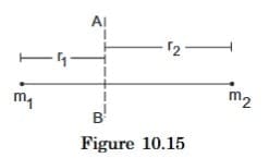
Solution: Moment of inertia of the particle on the left is m1 r1².
Moment of inertia of the particle on the right is m2 r2².
Moment of inertia of the rod is negligible as the rod is light.
Thus, the moment of inertia of the system about AB is m1 r1² + m2 r2².
Example 10.9: Three particles, each of mass m, are situated at the vertices of an equilateral triangle ABC of side L (figure 10.16). Find the moment of inertia of the system about the line AX perpendicular to AB in the plane of ABC.
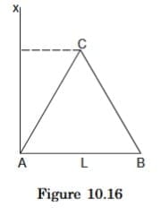
Solution: Perpendicular distance of A from AX = 0
B , , , = L
C , , , = L/2.
Thus, the moment of inertia of the particle at A = 0, of the particle at B = mL², and of the particle at C = m(L/2)². The moment of inertia of the three-particle system about AX is 0 + mL² + m(L/2)² = (5mL²)/4.
Note that we used dm = (M / (π R² l)) (2π x l dx) for the mass of the hollow cylinder in (E).
Moment of Inertia of Continuous Mass Distributions
If the body is assumed to be continuous, one can use the technique of integration to obtain its moment of inertia about a given line. Consider a small element of the body. The element should be so chosen that the perpendiculars from different points of the element to the given line differ only by infinitesimal amounts. Let its mass be dm and its perpendicular distance from the given line be r. Evaluate the product r² dm and integrate it over the appropriate limits to cover the whole body. Thus,
I = ∫ r² dm
under proper limits.
We can call r² dm the moment of inertia of the small element. Moment of inertia of the body about the given line is the sum of the moments of inertia of its constituent elements about the same line.
(A) Uniform Rod About A Perpendicular Bisector
Consider a uniform rod of mass M and length l (figure 10.17) and suppose the moment of inertia is to be calculated about the bisector AB. Take the origin at the middle point O of the rod. Consider the element of the rod between a distance x and x + dx from the origin. As the rod is uniform,
Mass per unit length of the rod = M/l
so that the mass of the element = (M/l)dx.
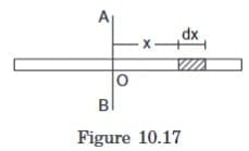
The perpendicular distance of the element from the line AB is x. The moment of inertia of this element about AB is
dl = (M/l) dx x².
When x = -l/2, the element is at the left end of the rod. As x is changed from -l/2 to l/2, the elements cover the whole rod.
Thus, the moment of inertia of the entire rod about AB is
I = ∫-l/2l/2 (M/l) x² dx = [ (M/l) (x³/3) ]-l/2l/2 = Ml²/12.
(B) Moment Of Inertia Of A Rectangular Plate About A Line Parallel To An Edge And Passing Through The Centre
The situation is shown in figure (10.18). Draw a line parallel to AB at a distance x from it and another at a distance x + dx. We can take the strip enclosed between the two lines as the small element.
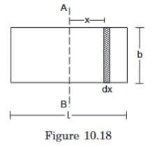
It is "small" because the perpendiculars from different points of the strip to AB differ by not more than dx. As the plate is uniform, its mass per unit area = M/(bl).
Mass of the strip = M/(bl) b dx = (M/l) dx.
The perpendicular distance of the strip from AB = x. The moment of inertia of the strip about AB = dl = (M/l) dx x². The moment of inertia of the given plate is, therefore,
I = ∫-l/2l/2 (M/l) x² dx = Ml²/12.
The moment of inertia of the plate about the line parallel to the other edge and passing through the centre may be obtained from the above formula by replacing l by b and thus,
I = Mb²/12.
(C) Moment of Inertia of a Circular Ring about Its Axis (The Line Perpendicular to the Plane of The Ring Through its Centre)
Suppose the radius of the ring is R and its mass is M. As all the elements of the ring are at the same perpendicular distance R from the axis, the moment of inertia of the ring about its axis is
I = ∫ r² dm = ∫ R² dm = R² ∫ dm = MR².
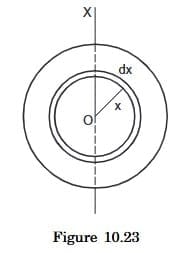
(D) Moment of Inertia of A Uniform Circular Plate About Its Axis
Let the mass of the plate be M and its radius R (figure 10.19). The centre is at O and the axis OX is perpendicular to the plane of the plate.
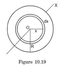
Draw two concentric circles of radii x and x + dx, both centred at O and consider the area of the plate in between the two circles.
This part of the plate may be considered to be a circular ring of radius x. As the periphery of the ring is 2πx and its width is dx, the area of this elementary ring is 2πx dx. The area of the plate is πR². As the plate is uniform, its mass per unit area = M / (π R²).
Mass of the ring = M / (π R²) 2π x dx = (2 M x dx) / R².
Using the result obtained above for a circular ring, the moment of inertia of the elementary ring about OX is
dI = [ (2 M x dx) / R² ] x².
The moment of inertia of the plate about OX is
I = ∫0R (2 M / R²) x³ dx = M R² / 2.
(E) Moment of inertia of a hollow cylinder about its axis
Suppose the radius of the cylinder is R and its mass is M. As every element of this cylinder is at the same perpendicular distance R from the axis, the moment of inertia of the hollow cylinder about its axis is
I = ∫R2dm = R2∫ dm = MR2.
(F) Moment of Inertia of a Hollow Cylinder about its Axis
Suppose the radius of the cylinder is R and its mass is M. As every element of this cylinder is at the same perpendicular distance R from the axis, the moment of inertia of the hollow cylinder about its axis is
I = ∫ R² dm = R² ∫ dm = MR².
(G) Moment of Inertia of a Uniform Solid Cylinder about its Axis
Let the mass of the cylinder be M and its radius R. Draw two cylindrical surfaces of radii x and x + dx coaxial with the given cylinder. Consider the part of the cylinder in between the two surfaces (figure 10.20). This part of the cylinder may be considered to be a hollow cylinder of radius x. The area of cross-section of the wall of this hollow cylinder is 2πx dx. If the length of the cylinder is l, the volume of the material of this elementary hollow cylinder is 2πx dx l.
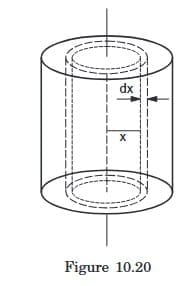
The volume of the solid cylinder is πR²l and it is uniform, hence its mass per unit volume is
ρ = M / (π R² l).
The mass of the hollow cylinder considered is
(M / (π R² l)) (2π x l dx) = (2 M x dx) / R².
As its radius is x, its moment of inertia about the given axis is
dI = [ (2 M x dx) / R² ] x² = (2 M / R²) x³ dx.
The moment of inertia of the solid cylinder is, therefore,
I = ∫0R (2 M / R²) x³ dx = M R² / 2.
Note that the formula does not depend on the length of the cylinder.
(H) Moment of Inertia of a Uniform Hollow Sphere about a Diameter
Let M and R be the mass and the radius of the sphere, O its centre and OX the given axis (figure 10.21). The mass is spread over the surface of the sphere and the inside is hollow.
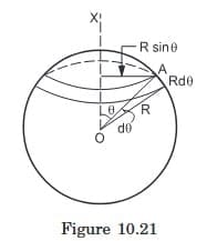
Let us consider a radius OA of the sphere at an angle θ with the axis OX and rotate this radius about OX. The point A traces a circle on the sphere. Now change θ to θ + dθ and get another circle of somewhat larger radius on the sphere. The part of the sphere between these two circles, shown in the figure, forms a ring of radius R sinθ. The width of this ring is Rdθ and its periphery is 2πR sinθ. Hence, the area of the ring = (2π R sinθ) (Rdθ).
Mass per unit area of the sphere = M / (4π R²).
The mass of the ring = M / (4π R²) (2π R sinθ) (Rdθ) = (M/2) sinθ dθ.
The moment of inertia of this elemental ring about OX is
dI = (M/2) sinθ dθ (R sinθ)².
= (M/2) R² sin³ θ dθ
As θ increases from 0 to π, the elemental rings cover the whole spherical surface. The moment of inertia of the hollow sphere is, therefore,
I = ∫0π (M/2) R² sin³ θ dθ = (MR²/2) [ ∫0π (1 - cos² θ) sin θ dθ ] = (-MR²/2) [ cos θ - (cos³ θ)/3 ]0π = (2/3) MR².
Alternative Method
Consider any particle P of the surface, having coordinates (xi, yi, zi) with respect to the centre O as the origin (figure 10.22) and OX as the X-axis. Let PQ be the perpendicular to OX. Then OQ = xi. That is the definition of x-coordinate.
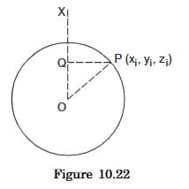
PQ² = OP² - OQ² = (xi² + yi² + zi²) - xi² = yi² + zi².
The moment of inertia of the particle P about the X-axis = mi (yi² + zi²).
The moment of inertia of the hollow sphere about the X-axis is, therefore,
Ix = ∑ mi (yi² + zi²).
Similarly, the moment of inertia of the hollow sphere about the Y-axis is
Iy = ∑ mi (zi² + xi²)
and about the Z-axis it is
Iz = ∑ mi (xi² + yi²)
Adding these three equations we get
Ix + Iy + Iz = ∑ 2 mi (xi² + yi² + zi²) = ∑ 2 mi R² = 2 MR².
As the mass is uniformly distributed over the entire surface of the sphere, all diameters are equivalent. Hence Ix, Iy and Iz must be equal.
Thus, I = (Ix + Iy + Iz) / 3 = (2/3) MR².
(I) Moment Of Inertia Of A Uniform Solid Sphere About A Diameter
Let M and R be the mass and radius of the given solid sphere. Let O be the centre and OX the given axis. Draw two spheres of radii x and x + dx concentric with the given solid sphere. The thin spherical shell trapped between these spheres may be treated as a hollow sphere of radius x.
The mass per unit volume of the solid sphere = 3M / (4π R³).
The thin hollow sphere considered has a surface area 4 π x² and thickness dx. Its volume is 4 π x² dx and hence its mass is = (3M / (4 π R³)) (4 π x² dx) = (3M / R³) x² dx.
Its moment of inertia about the diameter OX is, therefore,
dI = (2/3) [ (3M / R³) x² dx ] x² = (2 M / R³) x⁴ dx.
If x = 0, the shell is formed at the centre of the solid sphere. As x increases from 0 to R, the shells cover the whole solid sphere.
The moment of inertia of the solid sphere about OX is, therefore,
I = ∫0R (2 M / R³) x⁴ dx = (2/5) MR².
Two Important Theorems on Moment of Inertia
Theorem of Parallel Axes
Suppose we have to obtain the moment of inertia of a body about a given line AB (figure 10.24). Let C be the centre of mass of the body and let CZ be the line parallel to AB through C. Let I and I0 be the moments of inertia of the body about AB and CZ respectively. The parallel axes theorem states that
I = I0 + Md²
where d is the perpendicular distance between the parallel lines AB and CZ and M is the mass of the body.
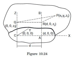
Take C to be the origin and CZ the Z-axis. Let CA be the perpendicular from C to AB. Take CA to be the X-axis. As CA = d, the coordinates of A are (d, 0, 0).
Let P be an arbitrary particle of the body with the coordinates (xi, yi, zi). Let PQ and PR be the perpendiculars from P to CZ and AB respectively. Note that P may not be in the plane containing CZ and AB. We have CQ = zi. Also AR = CQ = zi. Thus, the point Q has coordinates (0, 0, zi) and the point R has coordinates (d, 0, zi).
I = ∑ mi (PR)² = ∑ mi [ (xi - d)² + (yi - 0)² + (zi - zi)² ] = ∑ mi (xi² + yi² + d² - 2xi d) = ∑ mi (xi² + yi²) + ∑ mi d² - 2d ∑ mi xi (i)
We have
∑ mi xi = MXCM = 0.
The moment of inertia about CZ is,
I0 = ∑ mi (PQ)² = ∑ mi [(xi - 0)² + (yi - 0)² + (zi - zi)²] = ∑ mi (xi² + yi²)
From (i),
I = I0 + ∑ mi d² = I0 + Md².
Theorem of Perpendicular Axes
This theorem is applicable only to the plane bodies. Let X and Y-axes be chosen in the plane of the body and Z-axis perpendicular to this plane, three axes being mutually perpendicular. Then the theorem states that
Iz = Ix + Iy.
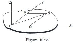
Consider an arbitrary particle P of the body (figure 10.25). Let PQ and PR be the perpendiculars from P on the X and the Y-axes respectively. Also PO is the perpendicular from P to the Z-axis. Thus, the moment of inertia of the body about the Z-axis is
Iz = ∑ mi (PO)² = ∑ mi (PQ² + OQ²) = ∑ mi (PQ² + PR²) = ∑ mi (PQ)² + ∑ mi (PR)² = Ix + Iy.
Example 10.10: Find the moment of inertia of a uniform ring of mass M and radius R about a diameter.
Solution:
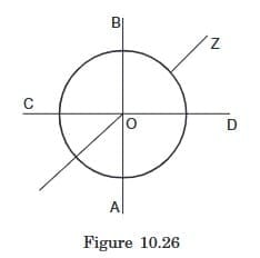
Let AB and CD be two mutually perpendicular diameters of the ring. Take them as X and Y-axes and the line perpendicular to the plane of the ring through the centre as the Z-axis. The moment of inertia of the ring about the Z-axis is I = MR². As the ring is uniform, all of its diameters are equivalent and so Ix = Iy. From perpendicular axes theorem,
Iz = Ix + Iy. Hence Ix = Iz/2 = MR²/2.
Example 10.11: Find the moment of inertia of a solid cylinder of mass M and radius R about a line parallel to the axis of the cylinder and on the surface of the cylinder.
Solution: The moment of inertia of the cylinder about its axis = MR²/2.
Using parallel axes theorem
I = I0 + MR² = MR²/2 + MR² = (3/2)MR².
Similarly, the moment of inertia of a solid sphere about a tangent is (2/5)MR² + MR² = (7/5)MR².
Radius of Gyration
The radius of gyration k of a body about a given line is defined by the equation
I = Mk²
where I is its moment of inertia about the given line and M is its total mass. It is the radius of a ring with the given line as the axis such that if the total mass of the body is distributed on the ring, it will have the same moment of inertia I. For example, the radius of gyration of a uniform disc of radius r about its axis is r/√2.
Combined Rotation And Translation
We now consider the motion of a rigid body which is neither pure translational nor pure rotational as seen from a lab. Suppose instead, there is a frame of reference A in which the motion of the rigid body is a pure rotation about a fixed line. If the frame A is also inertial, the motion of the body with respect to A is governed by the equations developed above. The motion of the body in the lab may then be obtained by adding the motion of A with respect to the lab to the motion of the body in A.
If the frame A is noninertial, we do not hope Γext = Iα to hold. In the derivation of this equation we used F = m α for each particle and this holds good only if α is measured from an inertial frame. If the frame A has an acceleration a in a fixed direction with respect to an inertial frame, we have to apply a pseudo force -m a to each particle. These pseudo forces produce a pseudo torque about the axis.
Pleasantly, there exists a very special and very useful case where Γext = Iα does hold even if the angular acceleration α is measured from a noninertial frame A. And that special case is, when the axis of rotation in the frame A passes through the centre of mass.
Take the origin at the centre of mass. The total torque of the pseudo forces is
∑ ri × (-mi a) = - ( ∑ mi ri ) × a = -M ( (∑ mi ri) / M ) × a
where ri is the position vector of the ith particle as measured from the centre of mass.
But (∑ mi ri) / M is the position vector of the centre of mass and that is zero as the centre of mass is at the origin. Hence the pseudo torque is zero and we get Γext = Iα. To make the point more explicit, we write Γcm = Icmα, reminding us that the equation is valid in a noninertial frame, only if the axis of rotation passes through the centre of mass and the torques and the moment of inertia are evaluated about the axis through the centre of mass.
So, the working rule for discussing combined rotation and translation is as follows. List the external forces acting on the body. The vector sum divided by the mass of the body gives the acceleration of the centre of mass. Then find the torque of the external forces and the moment of inertia of the body about a line through the centre of mass and perpendicular to the plane of motion of the particles. Note that this line may not be the axis of rotation in the lab frame. Still calculate Γ and I about this line. The angular acceleration α about the centre of mass will be obtained by α = Γ/I.
acm = Fext / M
α = Γcmext / Icm (10.15)
These equations together with the initial conditions completely determine the motion.
Rolling
When you go on a bicycle on a straight road what distance on the road is covered during one full pedal? Suppose a particular spoke of the bicycle is painted black and is vertical at some instant pointing downward. After one full pedal the spoke is again vertical in the similar position. We say that the wheel has made one full rotation. During this period the bicycle has moved through a distance 2πR in normal cycling on a good, free road. Here R is the radius of the wheel. The wheels are said to be 'rolling' on the road.
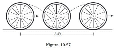
Looking from the road frame, the wheel is not making pure rotation about a fixed line. The particles of the wheel do not go on circles. The path of a particle at the rim will be something like that shown in figure (10.27), whereas the centre of the wheel goes in a straight line. But we still say that during one pedal the wheel has made one rotation, i.e., it has rotated through an angle of 2π. By this we mean that the spoke that was vertical (pointing downward from the centre) again became vertical in the similar position. In this period the centre of the wheel has moved through a distance 2πR. In half of this period, the wheel has moved through a distance πR and the spoke makes an angle of π with its original direction. During a short time-interval Δt, the wheel moves through a distance Δx and the spoke rotates by Δθ. Thus the wheel rotates and at the same time moves forward. The relation between the displacement of (the centre of) the wheel and the angle rotated by (a spoke of) the wheel is Δx = RΔθ. Dividing by Δt and taking limits, we get
v = Rω,
where v is the linear speed of the centre of mass and ω is the angular velocity of the wheel.
This type of motion of a wheel (or any other object with circular boundary) in which the centre of the wheel moves in a straight line and the wheel rotates in its plane about its centre with v = Rω, is called pure rolling.
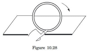
Place a ring on a horizontal surface as shown in figure (10.28) and put your finger on the lowest part. Use other hand to rotate the ring a little while the finger is kept on the lowest point. This is approximately a small part of rolling motion. Note the displacements of different particles of the ring. The centre has moved forward a little, say Δx. The topmost point has moved approximately double of this distance. The part in contact with the horizontal surface below the finger has almost been in the same position.
In pure rolling, the velocity of the contact point is zero. The velocity of the centre of mass is vcm = Rω and that of the topmost point is vtop = 2Rω = 2vcm.
Next, consider another type of combination of rotation and translation, in which the wheel moves through a distance greater than 2πR in one full rotation. Hold the ring of figure (10.28) between three fingers, apply a forward force to move it fast on the table and rotate it slowly through the fingers. Its angular velocity ω = dθ/dt is small and vcm > Rω. This is a case of rolling with forward slipping. This type of motion occurs when you apply sudden brakes to the bicycle on a road which is fairly smooth after rain. The cycle stops after a long distance and the wheel rotates only little during this period. If you look at the particles in contact, these will be found rubbing the road in the forward direction. The particles in contact have a velocity in the forward direction. In this case vcm > Rω. An extreme example of this type occurs when the wheel does not rotate at all and translates with linear velocity v. Then vcm = v and ω = 0.
Yet another type of rolling with slipping occurs when the wheel moves a distance shorter than 2πR while making one rotation. In this case, the velocity vcm < Rω. Hold the ring of figure (10.28) between three fingers, rotate it fast and translate it slowly. It will move a small distance on the table and rotate fast. If you drive a bicycle on a road on which a lot of mud is present, sometimes the wheel rotates fast but moves a little. If you look at the particles in contact, they rub the road in the backward direction. The centre moves less than 2πR during one full rotation and vcm < Rω.
These situations may be visualised in a different manner which gives another interpretation of rolling. Consider a wheel of radius r with its axis fixed in a second-hand car. The wheel may rotate freely about this axis. Suppose the floor of the second-hand car has a hole in it and the wheel just touches the road through the hole. Suppose the person sitting on the back seat rotates the wheel at a uniform angular velocity ω and the driver drives the car at a uniform velocity v on the road which is parallel to the plane of the wheel as shown in figure (10.29). The two motions are independent. The backseater is rotating the wheel at an angular velocity according to his will and the driver is driving the car at a velocity according to his will.
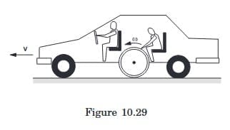
Look at the wheel from the road. If the persons inside the car agree to choose v and ω in such a way that v = ω r, the wheel is in pure rolling on the road. Looking from the road, the centre of the wheel is moving forward at a speed v and the wheel is rotating at an angular velocity ω with v = ω r. The velocity of the lowest particle with respect to the road = its velocity with respect to the car + velocity of the car with respect to the road. So,
vcontact, road = vcontact, car + vcar, road = -ω r + v = 0.
If the driver drives the car at a higher speed, v > ω r, the wheel rubs the road and we have rolling with forward slipping. In this case
vcontact, road = vcontact, car + vcar, road = -ω r + v > 0
Similarly, if v < ω r, we have rolling with backward slipping,
vcontact, road = -ω r + v < 0,
the particles at contact rub the road backward.
Kinetic Energy of a Body in Combined Rotation and Translation
Consider a body in combined translational and rotational motion in the lab frame. Suppose in the frame of the centre of mass, the body is making a pure rotation with an angular velocity ω. The centre of mass itself is moving in the lab frame at a velocity v0. The velocity of a particle of mass mi is vi, cm with respect to the centre-of-mass frame and vi with respect to the lab frame. We have,
vi = vi, cm + v0
The kinetic energy of the particle in the lab frame is
(1/2) mi vi² = (1/2) mi (vi, cm + v0) · (vi, cm + v0) = (1/2) mi vi, cm² + (1/2) mi v0² + (1/2) mi (2 vi, cm · v0).
Summing over all the particles, the total kinetic energy of the body in the lab frame is
K = ∑ (1/2) mi vi² = ∑ (1/2) mi vi, cm² + (1/2) ∑ mi v0² + ( ∑ mi vi, cm ) · v0.
Now ∑ (1/2) mi vi, cm² is the kinetic energy of the body in the centre of mass frame. In this frame, the body is making pure rotation with an angular velocity ω. Thus, this term is equal to (1/2) Icm ω². Also (∑ mi vi, cm) / M is the velocity of the centre of mass in the centre of mass frame which is obviously zero. Thus,
K = (1/2) Icm ω² + (1/2) M v0².
In the case of pure rolling, v0 = Rω so that
K = (1/2)(Icm + MR²)ω².
Using the parallel axes theorem, Icm + MR² = I, which is the moment of inertia of the wheel about the line through the point of contact and parallel to the axis. Thus, K = (1/2) I ω².
This gives another interpretation of rolling. At any instant a rolling body may be considered to be in pure rotation about an axis through the point of contact. This axis translates forward with a speed v0.
Angular Momentum Of A Body In Combined Rotation And Translation
Consider the situation described in the previous section. Let O be a fixed point in the lab which we take as the origin. Angular momentum of the body about O is
L = ∑ mi ri × vi = ∑ mi (ri, cm + r0) × (vi, cm + v0).
Here, r0 is the position vector of the centre of mass. Thus,
L = ∑ mi (ri, cm × vi, cm) + ( ∑ mi ri, cm ) × v0 + r0 × ( ∑ mi vi, cm ) + ( ∑ mi ) r0 × v0.
∑ mi ri, cm = M Rcm, cm = 0
∑ mi vi, cm = M Vcm, cm = 0.
Thus, L = ∑ mi (ri, cm × vi, cm) + M r0 × v0 = Lcm + M r0 × v0.
The first term Lcm represents the angular momentum of the body as seen from the centre-of-mass frame. The second term M r0 × v0 equals the angular momentum of the body if it is assumed to be concentrated at the centre of mass translating with the velocity v0.
10.20 Why Does A Rolling Sphere Slow Down ?
When a sphere is rolled on a horizontal table it slows down and eventually stops. Figure (10.30) shows the situation. The forces acting on the sphere are (a) weight mg, (b) friction at the contact and (c) the normal force. As the centre of the sphere decelerates, the friction should be opposite to its velocity, that is towards left in figure (10.30). But this friction will have a clockwise torque that should increase the angular velocity of the sphere. There must be an anticlockwise torque that causes the decrease in the angular velocity.
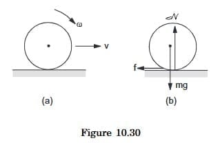
In fact, when the sphere rolls on the table, both the sphere and the surface deform near the contact. The contact is not at a single point as we normally assume, rather there is an area of contact. The front part pushes the table a bit more strongly than the back part. As a result, the normal force does not pass through the centre, it is shifted towards the right. This force, then, has an anticlockwise torque. The net torque causes an angular deceleration.
Worked Out Examples
Example 1: A Wheel Rotates With A Constant Acceleration Of 2.0 Rad/s². If The Wheel Starts From Rest, How Many Revolutions Will It Make In The First 10 Seconds?
Solution: The angular displacement in the first 10 seconds is given by
θ = ω0 t + (1/2) α t² = (1/2) (2.0 rad/s²) (10 s)² = 100 rad.
As the wheel turns by 2π radian in each revolution, the number of revolutions in 10 s is
n = 100 / (2π) = 16.
Example 2: The Wheel Of A Motor, Accelerated Uniformly From Rest, Rotates Through 2.5 Radian During The First Second. Find The Angle Rotated During The Next Second.
Solution: As the angular acceleration is constant, we have
θ = ω0 t + (1/2) α t² = (1/2) α t².
Thus,
2.5 rad = (1/2) α (1 s)² α = 5 rad/s²
or,
α = 5 rad/s².
The angle rotated during the first two seconds is
= (1/2) × (5 rad/s²) (2 s)² = 10 rad.
Thus, the angle rotated during the 2nd second is
10 rad - 2.5 rad = 7.5 rad.
Example 3: A Wheel Having Moment Of Inertia 2 Kg-m² About Its Axis, Rotates At 50 Rpm About This Axis. Find The Torque That Can Stop The Wheel In One Minute.
Solution: The initial angular velocity = 50 rpm = (5π/3) rad/s.
Using ω = ω0 + α t,
α = (ω - ω0) / t = (0 - 5π/3) / 60 rad/s² = -π/36 rad/s².
The torque that can produce this deceleration is
Γ = I |α| = (2 kg-m²) (π/36 rad/s²) = π/18 N-m.
FAQs on HC Verma Summary: Rotational Motion - 2
| 1. What is angular impulse and how does it relate to angular momentum? |  |
| 2. How is the kinetic energy of a rigid body rotating about a given axis calculated? | |
| 3. What is the relationship between power delivered by a torque and work done? | |
| 4. What are the two important theorems on moment of inertia? | |
| 5. Why does a rolling sphere slow down over time? | |


