Ethernet Frames


Ethernet Frames
An Ethernet frame is the fundamental unit of data transmission in Ethernet networks. When you send information across a local network-whether it's loading a webpage, sending an email, or streaming a video-that data travels in carefully structured packages called frames. Think of a frame as an envelope: it contains the actual message you want to send, along with important addressing and verification information that helps the network deliver it correctly. Understanding Ethernet frames is essential to understanding how local networks function at their most basic level.
What is a Frame?
Before diving into Ethernet frames specifically, let's clarify what a frame is in networking terms. A frame is a unit of data at the Data Link Layer (Layer 2) of the OSI model. It encapsulates higher-level data (like IP packets) by adding headers and trailers that contain information needed for local network delivery.
Analogy: If you're mailing a letter, the letter itself is your message. The envelope with the recipient's address, return address, and postal stamps is like the frame-it provides the information necessary to deliver the letter through the postal system.
The term "frame" is used specifically at Layer 2. At other layers, data units have different names:
- Bits at the Physical Layer (Layer 1)
- Frames at the Data Link Layer (Layer 2)
- Packets at the Network Layer (Layer 3)
- Segments at the Transport Layer (Layer 4)
Purpose of Ethernet Frames
Ethernet frames serve several critical functions in network communication:
- Addressing: Frames identify both the sender and the intended receiver using MAC addresses, ensuring data reaches the correct device on the local network.
- Data Encapsulation: Frames wrap higher-layer data (like IP packets) in a standardized format that Ethernet hardware can process.
- Error Detection: Frames include error-checking information that allows receiving devices to detect if data was corrupted during transmission.
- Synchronization: Frames include fields that help receiving devices recognize when a new frame is starting and align their reception timing.
- Type Identification: Frames indicate what type of data they're carrying (such as IPv4, IPv6, or ARP), allowing the receiving device to process it correctly.
Ethernet Frame Structure
An Ethernet frame consists of several distinct fields, each with a specific purpose. The most commonly used Ethernet frame format today is Ethernet II (also called DIX Ethernet, named after Digital, Intel, and Xerox, the companies that developed it). Let's examine each field in detail.
Complete Ethernet II Frame Layout
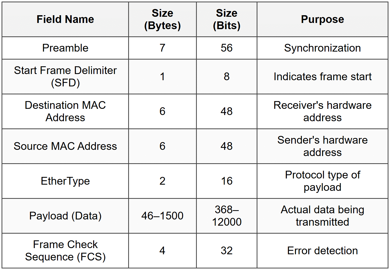
Let's explore each field in detail.
Preamble
The preamble is a 7-byte field consisting of alternating 1s and 0s (10101010 repeated seven times). Its purpose is to help the receiving network interface card (NIC) synchronize its receiver clock with the incoming signal.
Analogy: Think of the preamble like a conductor tapping the music stand before an orchestra begins playing. It helps everyone get in sync and ready for what's coming.
The pattern is: 10101010 10101010 10101010 10101010 10101010 10101010 10101010
This field operates at the physical layer and is often considered separate from the frame itself in some technical discussions, but it's essential for successful frame reception.
Start Frame Delimiter (SFD)
The Start Frame Delimiter is a 1-byte field with the pattern 10101011. Notice that it's almost identical to the preamble bytes, but the last two bits are 11 instead of 10. This signals to the receiving device that the actual frame content is about to begin.
After the SFD, the receiving device knows that the next byte will be the start of the destination MAC address.
Destination MAC Address
The destination MAC address is a 6-byte (48-bit) field that specifies the hardware address of the intended recipient. A MAC address (Media Access Control address) is a unique identifier assigned to every network interface card.
MAC addresses are typically written in hexadecimal format, such as: 00:1A:2B:3C:4D:5E or 00-1A-2B-3C-4D-5E
There are three types of destination addresses:
- Unicast: A specific single device (first byte's least significant bit is 0)
- Multicast: A group of devices (first byte's least significant bit is 1)
- Broadcast: All devices on the network (address is FF:FF:FF:FF:FF:FF)
Source MAC Address
The source MAC address is a 6-byte field that identifies the device that created and sent the frame. This allows the receiver to know where the frame came from and to send replies if needed.
The source MAC address is always a unicast address-frames can never legitimately be sent from a multicast or broadcast address.
EtherType
The EtherType field is a 2-byte field that indicates what type of protocol data is contained in the payload. This tells the receiving device how to interpret and process the data.
Common EtherType values include:
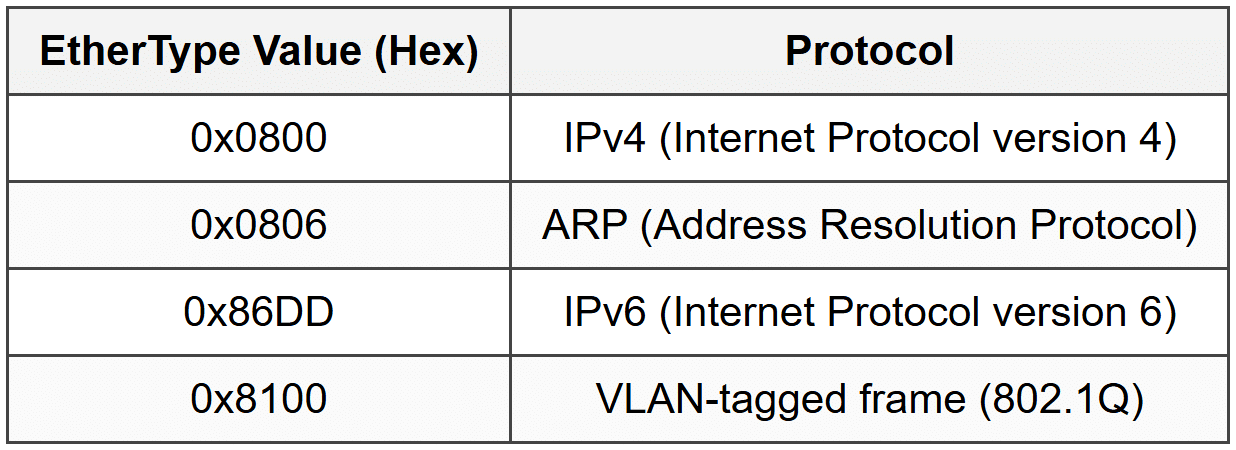
For example, if the EtherType value is 0x0800, the receiving device knows the payload contains an IPv4 packet and should pass it to the IP layer for further processing.
Payload (Data Field)
The payload is the actual data being transmitted. This field carries the higher-layer protocol information-typically an IP packet, but it could also be ARP data, IPv6 packets, or other protocol data units.
The payload size has important constraints:
- Minimum size: 46 bytes
- Maximum size: 1500 bytes
The maximum payload size of 1500 bytes is called the Maximum Transmission Unit (MTU) for standard Ethernet. If the data to be sent is larger than 1500 bytes, it must be split into multiple frames.
If the actual data is smaller than 46 bytes, padding (extra zeros) is added to reach the minimum size. This minimum size requirement helps with collision detection in traditional Ethernet networks.
Note: Some modern Ethernet implementations support "jumbo frames" with payloads up to 9000 bytes, but these are not part of the standard Ethernet specification and require all network equipment to support them.
Frame Check Sequence (FCS)
The Frame Check Sequence is a 4-byte field used for error detection. It contains a Cyclic Redundancy Check (CRC) value calculated based on the frame's contents.
Here's how it works:
- The sending device performs a mathematical calculation (CRC-32) on the frame's data
- The result is placed in the FCS field
- The receiving device performs the same calculation on the received data
- If the calculated value matches the FCS value, the frame is assumed to be intact
- If they don't match, the frame has been corrupted and is discarded
Analogy: The FCS is like a seal on a package. If the seal is broken or doesn't match, you know something went wrong during delivery and the contents might be damaged.
Important: The FCS can detect errors but cannot correct them. If an error is detected, the frame is simply dropped, and upper-layer protocols (like TCP) handle retransmission if needed.
Frame Size Constraints
Understanding Ethernet frame size limits is crucial for network design and troubleshooting.
Minimum Frame Size
The minimum Ethernet frame size is 64 bytes (excluding the preamble and SFD). This breaks down as:
Destination MAC: 6 bytes
Source MAC: 6 bytes
EtherType: 2 bytes
Payload: 46 bytes (minimum)
FCS: 4 bytes
Total: 64 bytes
The minimum size requirement exists to ensure proper collision detection in traditional half-duplex Ethernet networks. If a frame is too small, a collision might occur, and the sending device might finish transmitting before it detects the collision.
If the actual data is less than 46 bytes, the system adds padding (zeros) to meet the minimum requirement.
Maximum Frame Size
The maximum Ethernet frame size is 1518 bytes (excluding preamble and SFD). This consists of:
Destination MAC: 6 bytes
Source MAC: 6 bytes
EtherType: 2 bytes
Payload: 1500 bytes (maximum)
FCS: 4 bytes
Total: 1518 bytes
For VLAN-tagged frames (802.1Q), the maximum is 1522 bytes due to the additional 4-byte VLAN tag.
Frames that exceed the maximum size are called jabber frames or giant frames and are considered errors. Frames smaller than the minimum are called runt frames.
The Interframe Gap
Between consecutive Ethernet frames, there must be a brief pause called the Interframe Gap (IFG) or Interpacket Gap (IPG). This gap is 96 bits (12 bytes) of idle time.
The purpose of the IFG is to:
- Give receiving devices time to process the previous frame
- Allow network hardware to prepare for the next frame
- Prevent frames from running together and becoming indistinguishable
Analogy: The IFG is like the pause between words when speaking. Without pauses, all the words would run together and become unintelligible.
At 1 Gbps Ethernet, 96 bits takes 96 nanoseconds. The IFG is enforced at the physical layer.
IEEE 802.3 Frame Format
While Ethernet II is the most common frame format today, you should be aware that another format exists: the IEEE 802.3 frame format. This format was developed by the IEEE standards committee and has a slightly different structure.
Key Differences from Ethernet II
In the IEEE 802.3 format, the 2-byte field that corresponds to EtherType in Ethernet II is instead a Length field that specifies the size of the payload.
To identify the protocol type, the 802.3 format uses additional headers within the payload:
- LLC (Logical Link Control) header: Provides basic protocol identification
- SNAP (Subnetwork Access Protocol) header: Can be added for more detailed protocol identification
Distinguishing Between Frame Types
How can a receiving device tell whether a frame is Ethernet II or 802.3? The answer lies in the value of the 2-byte field after the MAC addresses:
- If the value is ≥ 1536 (0x0600), it's an EtherType field (Ethernet II)
- If the value is ≤ 1500, it's a Length field (IEEE 802.3)
This works because the maximum payload size is 1500 bytes, so a value of 1500 or less makes sense as a length. EtherType values are assigned starting from 1536, so any value 1536 or higher must be a protocol type, not a length.
Note: In modern networks, Ethernet II frames are far more common. IEEE 802.3 frames with LLC/SNAP are primarily encountered in legacy systems or specific enterprise applications.
MAC Addresses in Detail
Since MAC addresses are fundamental to Ethernet frames, let's explore them more thoroughly.
MAC Address Structure
A MAC address is 48 bits (6 bytes) long and is typically represented in hexadecimal notation. Each hexadecimal digit represents 4 bits, so 12 hexadecimal digits represent 48 bits.
Example: A4:5E:60:E8:2B:3C
A MAC address is divided into two halves:
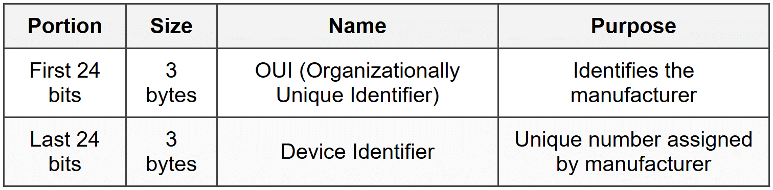
The OUI is assigned by the IEEE to manufacturers. For example, all network cards made by Cisco will share the same OUI prefix, but each will have a unique device identifier.
Special Bits in MAC Addresses
Within the first byte of a MAC address, two specific bits have special meaning:
Least Significant Bit of First Byte (I/G Bit)
The Individual/Group (I/G) bit determines whether the address is unicast or multicast:
- 0: Unicast (individual device)
- 1: Multicast (group of devices)
Second Least Significant Bit of First Byte (U/L Bit)
The Universal/Local (U/L) bit indicates whether the address is globally unique or locally administered:
- 0: Universally administered (assigned by manufacturer)
- 1: Locally administered (manually configured)
Broadcast MAC Address
The broadcast MAC address is a special address consisting of all 1s: FF:FF:FF:FF:FF:FF
Frames sent to this address are delivered to all devices on the local network segment. This is commonly used by protocols like ARP when a device needs to find another device's MAC address.
How Frames Are Processed
Understanding how devices handle Ethernet frames helps clarify why each field exists.
Sending a Frame
When a device wants to send data:
- The higher-layer protocol (like IP) provides data to be sent and the destination IP address
- The device determines the destination MAC address (using ARP if necessary)
- The Ethernet driver creates a frame:
- Adds the destination MAC address
- Adds its own MAC address as the source
- Sets the appropriate EtherType
- Adds the payload data (padding if necessary)
- Calculates and adds the FCS
- The physical layer adds the preamble and SFD
- The frame is transmitted as electrical signals, light pulses, or radio waves
Receiving a Frame
When a device receives a frame:
- The physical layer detects the preamble and synchronizes
- The SFD indicates the frame is starting
- The network interface card reads the destination MAC address
- The NIC checks if the destination matches:
- Its own MAC address (unicast)
- A multicast group it belongs to
- The broadcast address (FF:FF:FF:FF:FF:FF)
- If not in promiscuous mode and none match, the frame is ignored
- The entire frame is received and the FCS is checked
- If the FCS is correct, the frame is accepted; otherwise, it's discarded
- The EtherType is examined to determine which protocol should receive the payload
- The payload is passed to the appropriate higher-layer protocol (like IP)
Promiscuous Mode: Network interfaces can be configured in promiscuous mode, which means they accept all frames regardless of destination address. This is used for network monitoring and analysis tools like Wireshark.
Frame Transmission and Bandwidth
Understanding how frames relate to network bandwidth helps in capacity planning and troubleshooting.
Calculating Transmission Time
The time it takes to transmit a frame depends on its size and the network speed. The formula is:
[/[ \text{Transmission Time} = \frac{\text{Frame Size (bits)}}{\text{Bandwidth (bits per second)} } ]/]
Where Transmission Time is the time in seconds, Frame Size is the total frame size in bits, and Bandwidth is the network speed in bits per second.
Example: How long does it take to transmit a minimum-sized frame (64 bytes) on a 100 Mbps Ethernet link?
Frame size = 64 bytes = 64 × 8 = 512 bits
Bandwidth = 100 Mbps = 100,000,000 bits/second
Transmission time = 512 ÷ 100,000,000
Transmission time = 0.00000512 seconds
Transmission time = 5.12 microseconds
Effective Throughput
Not all bandwidth is available for actual data. The frame overhead (headers, FCS, preamble, IFG) reduces effective throughput. For maximum-sized frames, efficiency is higher because the overhead is proportionally smaller.
For a 1500-byte payload frame:
Useful data: 1500 bytes
Frame overhead: 18 bytes (6+6+2+4)
Preamble + SFD: 8 bytes
Interframe Gap: 12 bytes
Total overhead: 38 bytes
Efficiency = 1500 ÷ (1500 + 38) = 1500 ÷ 1538 ≈ 97.5%
For a minimum-sized frame (46-byte payload):
Useful data: 46 bytes
Total with overhead: 84 bytes (frame + preamble + IFG)
Efficiency = 46 ÷ 84 ≈ 54.8%
This shows that larger frames use bandwidth more efficiently.
VLAN Tagging and Frame Modification
Modern Ethernet networks often use Virtual LANs (VLANs) to logically segment networks. VLAN information is added to Ethernet frames using the 802.1Q standard.
802.1Q VLAN Tag
A VLAN tag is a 4-byte field inserted into the Ethernet frame between the source MAC address and the EtherType field:
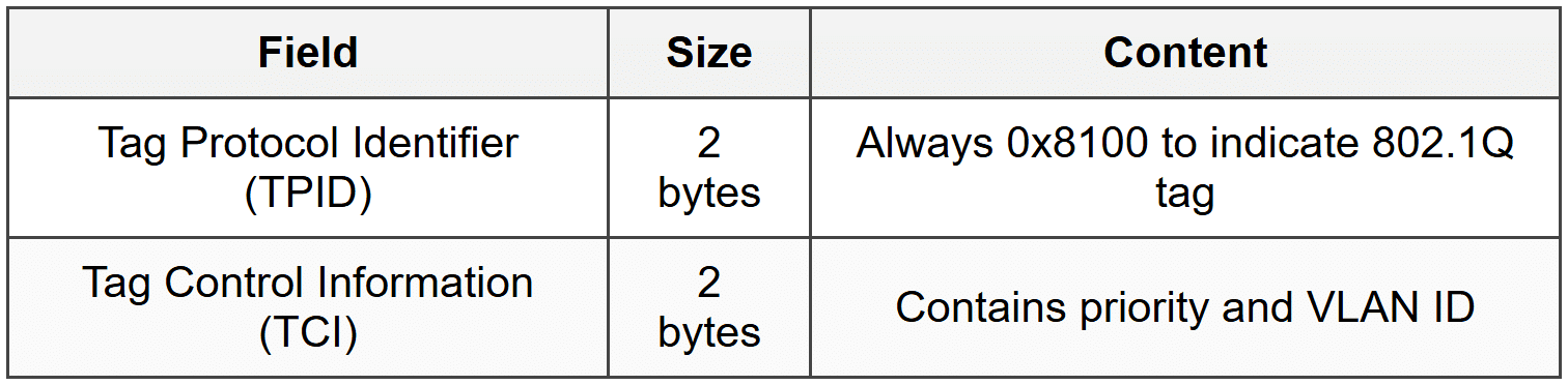
The TCI field is further subdivided:
- Priority Code Point (PCP): 3 bits for Quality of Service priority (0-7)
- Drop Eligible Indicator (DEI): 1 bit indicating if frame can be dropped during congestion
- VLAN Identifier (VID): 12 bits identifying the VLAN (0-4095)
With the VLAN tag, the maximum frame size becomes 1522 bytes instead of 1518 bytes.
Tagged vs. Untagged Frames
- Untagged frames: Standard Ethernet II frames without VLAN information
- Tagged frames: Frames with an 802.1Q VLAN tag inserted
Network switches can be configured to add tags (when frames enter the switch from an access port) or remove tags (when frames exit to an access port). Trunk ports between switches typically carry tagged frames for multiple VLANs.
Error Detection: CRC in Detail
The Frame Check Sequence uses a specific error-detection algorithm called CRC-32 (32-bit Cyclic Redundancy Check). While the mathematical details are complex, understanding the principle is valuable.
How CRC Works
- The sender treats the frame data as a very large binary number
- This number is divided by a predetermined polynomial (a specific binary value)
- The remainder of this division becomes the FCS value
- The receiver performs the same division on the received data
- If the remainder matches the received FCS, no error is detected
The polynomial used for Ethernet CRC-32 is:
(/(x^{32} + x^{26} + x^{23} + x^{22} + x^{16} + x^{12} + x^{11} + x^{10} + x^8 + x^7 + x^5 + x^4 + x^2 + x + 1/)/)
Note: You don't need to perform CRC calculations manually-network hardware does this automatically. However, understanding that it's a mathematical check helps you appreciate its reliability and limitations.
What CRC Can and Cannot Detect
CRC-32 is very effective at detecting:
- All single-bit errors
- All double-bit errors
- All errors affecting an odd number of bits
- All burst errors of 32 bits or less
- Most longer burst errors
However, CRC cannot:
- Correct errors-it can only detect them
- Detect all possible errors (though the probability of undetected errors is extremely low)
- Detect intentional malicious modifications (it's not a security mechanism)
Frame Handling Scenarios
Let's examine some common scenarios involving Ethernet frames to solidify understanding.
Scenario 1: ARP Request
When a device needs to find the MAC address for a known IP address, it uses the Address Resolution Protocol (ARP):
- The source device creates an ARP request packet
- It encapsulates this in an Ethernet frame with:
- Destination MAC: FF:FF:FF:FF:FF:FF (broadcast)
- Source MAC: Its own MAC address
- EtherType: 0x0806 (ARP)
- All devices on the local network receive the frame
- Only the device with the matching IP address responds with an ARP reply containing its MAC address
Scenario 2: IP Packet Transmission
When sending an IP packet to another device on the same network:
- The source device has an IP packet to send
- It knows the destination IP and uses ARP to find the destination MAC (or retrieves it from its ARP cache)
- It creates an Ethernet frame:
- Destination MAC: The destination device's MAC
- Source MAC: Its own MAC
- EtherType: 0x0800 (IPv4)
- Payload: The IP packet
- The frame is transmitted
- Only the device with the matching destination MAC processes the frame fully
Scenario 3: Sending to a Remote Network
When sending to a device on a different network (through a router):
- The source device determines the destination is not on the local network
- It addresses the frame to the default gateway (router) MAC address, not the final destination
- The EtherType still indicates the protocol (IPv4/IPv6)
- The router receives the frame, extracts the IP packet, and determines the next hop
- The router creates a new frame with:
- Its own MAC as the source
- The next hop's MAC as the destination
- The same IP packet as the payload
Key Point: Ethernet frames operate only on the local network segment. MAC addresses in frames change at each router hop, but the IP packet inside remains the same (except for TTL and checksum updates).
Common Frame Errors and Issues
Network administrators frequently encounter frame-related problems. Understanding these helps with troubleshooting.
Types of Frame Errors
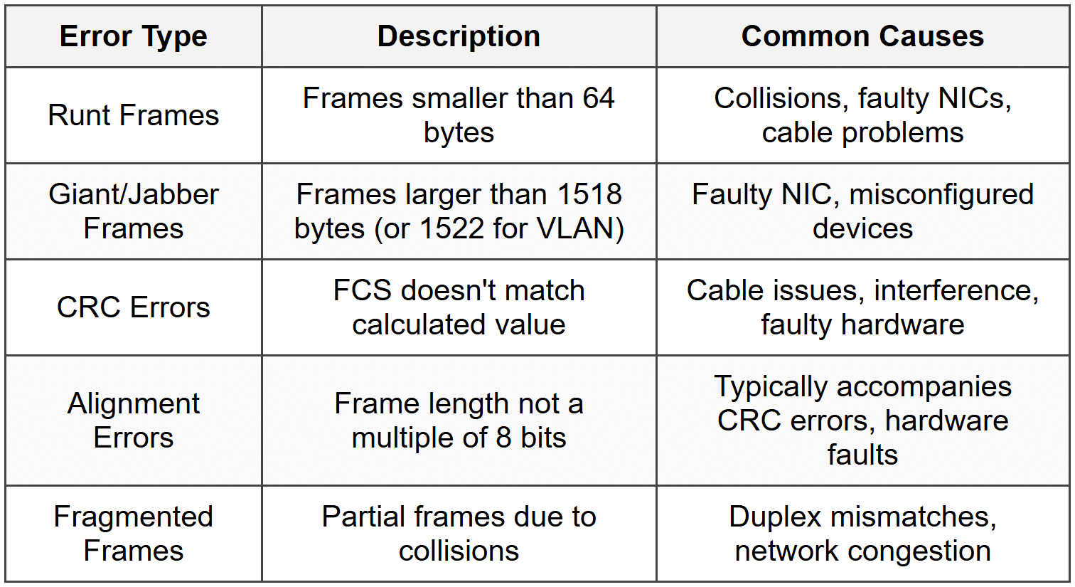
Frame Drops
Frames may be dropped (discarded) for several reasons:
- Failed FCS check: The most common reason-indicates corruption during transmission
- Buffer overflow: The receiving device's memory is full and can't accept more frames
- Size violations: Runt or giant frames are automatically dropped
- Destination filtering: The NIC doesn't match the destination MAC and isn't in promiscuous mode
- VLAN mismatches: Frame is tagged for a VLAN the port doesn't belong to
Dropped frames don't generate error messages at the Ethernet level. Higher-layer protocols (like TCP) detect the loss through missing acknowledgments and retransmit.
Capturing and Analyzing Frames
Network professionals use tools to capture and examine Ethernet frames for troubleshooting and analysis.
Packet Capture Tools
The most common tool is Wireshark, which can capture frames from a network interface and display their contents in detail. Other tools include:
- tcpdump: Command-line packet analyzer for Unix/Linux systems
- Microsoft Network Monitor: Windows-based packet capture
- Cisco Packet Tracer: Simulation tool for educational purposes
Reading a Frame Capture
When you capture a frame, you'll see information organized by layer:
- Frame information: Total size, arrival time, frame number
- Ethernet II layer: Source and destination MAC addresses, EtherType
- Network layer: IP addresses, protocol (if IP)
- Transport layer: Port numbers, sequence numbers (if TCP/UDP)
- Application layer: Protocol-specific data (HTTP, DNS, etc.)
The hexadecimal dump shows the raw bytes of the frame, while the packet analyzer decodes and interprets each field.
Analogy: Think of a packet analyzer as an X-ray machine for network traffic. It lets you see inside each frame and understand exactly what information it contains and how it's structured.
Evolution of Ethernet Framing
Understanding the historical context helps explain why Ethernet frames are designed as they are.
Original Ethernet (DIX)
Developed in the 1970s by Xerox, and later refined by Digital, Intel, and Xerox (DIX), the original Ethernet used a shared coaxial cable and operated at 10 Mbps. The Ethernet II frame format from this era remains the dominant format today.
IEEE Standardization
In the 1980s, the IEEE created the 802.3 standard, which introduced the alternative frame format with LLC/SNAP. This was intended to support multiple protocol stacks (not just IP), but the industry largely continued using Ethernet II frames.
Modern Ethernet
Today's Ethernet operates at speeds from 10 Mbps to 400 Gbps and uses twisted-pair cables or fiber optics instead of coaxial cable. However, the basic frame structure remains remarkably similar to the original design, demonstrating the robustness of the format.
Key improvements in modern Ethernet include:
- Full-duplex operation (eliminating collisions)
- Switched networks (replacing shared media)
- Power over Ethernet (PoE) capability
- Energy Efficient Ethernet standards
Despite these advances, the fundamental frame format has remained stable, ensuring backward compatibility.
Practical Considerations
Frame Size and Application Performance
The choice of frame size affects performance. Larger frames mean:
- Advantages:
- Better efficiency (less overhead per data byte)
- Fewer frames to process for the same amount of data
- Lower CPU utilization on network devices
- Disadvantages:
- Longer transmission time, which can increase latency
- Greater impact if a frame is lost or corrupted
- Larger probability of encountering errors during transmission
For real-time applications like voice or video, smaller frames may be preferable despite lower efficiency, because they reduce latency and jitter.
Jumbo Frames
Some networks use jumbo frames with payloads up to 9000 bytes to increase efficiency for large data transfers. However:
- All devices in the path must support jumbo frames
- They're not part of the IEEE standard
- Different vendors may implement different maximum sizes
- They're typically used only in specialized environments like storage networks or data centers
Network Design Implications
Understanding frames is essential for proper network design:
- Switch capacity: Must be able to handle the frame rate, not just bandwidth. A 10 Gbps switch handling minimum-sized frames needs much higher processing capability than one handling maximum-sized frames at the same bandwidth.
- Buffer sizing: Switches need sufficient buffer memory to hold frames during congestion periods.
- VLAN planning: Understand how VLAN tags affect frame size and maximum frame counts per second.
Review Questions
- What is the purpose of the preamble in an Ethernet frame, and how long is it?
- What are the minimum and maximum sizes of an Ethernet frame (excluding preamble and SFD), and why do these limits exist?
- Explain the difference between the EtherType field in Ethernet II frames and the corresponding field in IEEE 802.3 frames.
- How can a receiving device distinguish between an Ethernet II frame and an IEEE 802.3 frame?
- What is the purpose of the Frame Check Sequence (FCS), and what happens when an error is detected?
- What is padding in an Ethernet frame, and when is it necessary?
- Describe the structure of a MAC address and explain what the OUI represents.
- What is the broadcast MAC address, and when would a device send a frame to this address?
- Calculate the transmission time for a maximum-sized Ethernet frame (1518 bytes) on a 1 Gbps link.
- What is the Interframe Gap, and why is it necessary?
- Explain what happens to the destination MAC address when a frame passes through a router on its way to a remote network.
- What is a runt frame, and what typically causes such frames?
- How does VLAN tagging (802.1Q) modify the Ethernet frame structure?
- Why is the minimum Ethernet frame size 64 bytes, and what problem does this solve?
- What is the difference between a unicast, multicast, and broadcast destination MAC address?
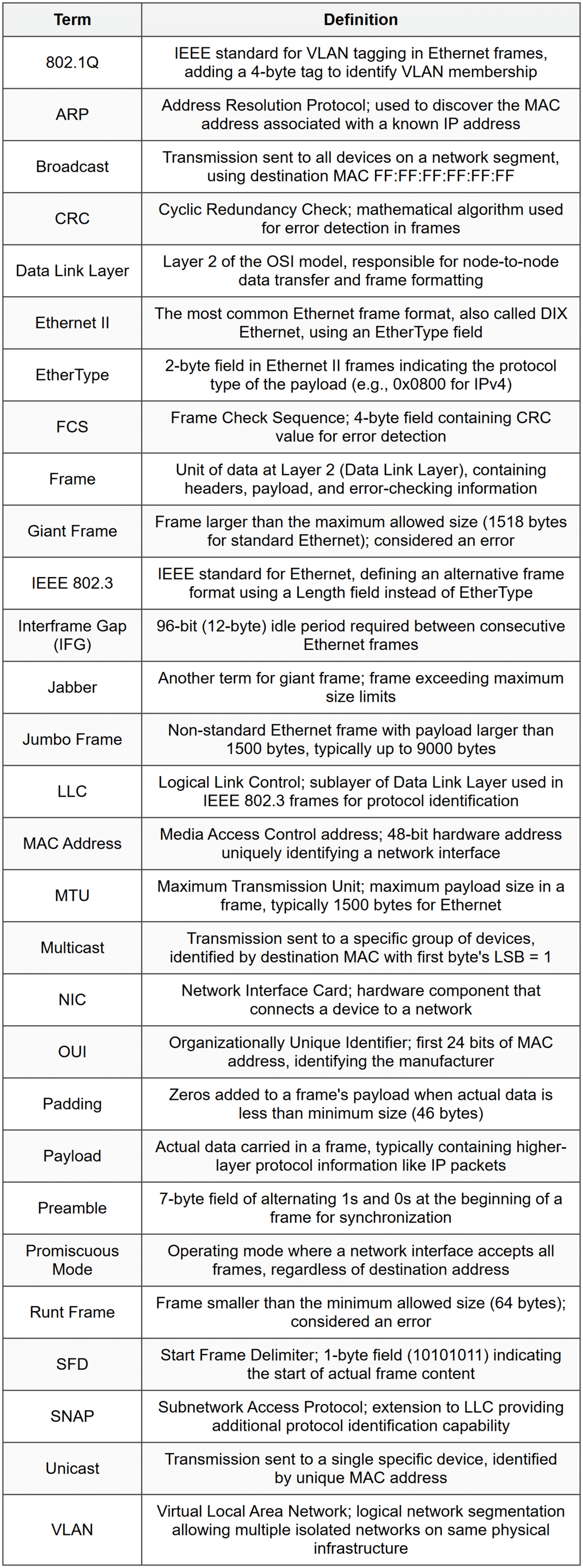
Glossary