Physical vs Logical Topology


Physical vs Logical Topology
When we talk about computer networks, we are describing how different devices like computers, printers, and servers connect and communicate with each other. To understand these networks fully, we need to look at them from two different perspectives: how they are physically arranged (the actual wires and hardware you can touch) and how data actually flows through them (the path information takes). These two perspectives are called physical topology and logical topology. Understanding the difference between these two concepts is essential because a network's physical layout doesn't always match how data travels through it.
What is Network Topology?
Before we dive into the differences, let's understand what topology means in networking. The word "topology" comes from mathematics and simply means "arrangement" or "structure." In computer networking, topology refers to the arrangement of various elements (links, nodes, devices) in a network.
Every network has two types of arrangements:
- The physical arrangement - where devices and cables are actually located
- The logical arrangement - how data flows between devices
Think of a city's transportation system. The physical topology is like looking at a map showing where all the roads, highways, and streets are actually built. The logical topology is like looking at a bus route map that shows which path the bus actually takes to get from point A to point B, even though many other roads exist.
Physical Topology
Physical topology refers to the actual, tangible layout of the network. It describes the physical arrangement of devices, cables, and other network components. When you look at physical topology, you're examining:
- Where each device is physically located
- How cables are actually connected between devices
- The type of cables used (copper, fiber optic, etc.)
- The physical distance between devices
- The placement of network hardware like switches, routers, and hubs
Characteristics of Physical Topology
Physical topology has several important characteristics that distinguish it:
- Visible and tangible: You can see and touch the physical topology. You can trace cables from one device to another.
- Installation-dependent: The physical topology depends on how the network was installed in the building or location.
- Affects cost: Physical topology directly impacts the amount of cabling needed, which affects the overall cost of the network.
- Affects troubleshooting: When physical problems occur (like a broken cable), you need to understand the physical topology to fix them.
- May include redundant paths: Sometimes extra cables are installed for backup purposes, even if they aren't normally used.
Common Physical Topology Types
Bus Physical Topology
In a bus physical topology, all devices connect to a single central cable called the backbone or bus. This main cable runs through the area, and each device taps into it.
Imagine a train track with multiple stations along a single line. Each station connects to the same track, just as each computer connects to the same cable in a bus topology.
Star Physical Topology
In a star physical topology, each device has its own dedicated cable that connects directly to a central device (usually a switch or hub). All cables radiate out from this central point like the points of a star.
This is the most common physical topology in modern networks, especially in office buildings and homes.
Ring Physical Topology
In a ring physical topology, devices are connected in a closed loop. Each device connects to exactly two other devices, forming a circular pathway for signals.
Mesh Physical Topology
In a mesh physical topology, devices have multiple connections to other devices. In a full mesh, every device connects to every other device. In a partial mesh, some devices connect to multiple others, but not all possible connections exist.
Factors Influencing Physical Topology Choice
Network designers choose physical topologies based on several practical considerations:
- Building layout: The physical structure of the building affects where cables can be run
- Cable length limitations: Different cable types have maximum length restrictions
- Budget: More complex topologies require more cable and may cost more
- Future expansion: Some topologies make it easier to add new devices later
- Fault tolerance: Some topologies continue working even if a cable breaks
Logical Topology
Logical topology refers to the way data actually flows through the network, regardless of the physical layout. It describes the path that data takes from one device to another and how devices communicate at the data link layer of the network.
The logical topology is determined by:
- The network protocol being used
- How network devices are configured
- The network access method (how devices decide when to transmit)
- The actual path data packets take through the network
Characteristics of Logical Topology
Logical topology has distinct characteristics:
- Invisible: You cannot see the logical topology just by looking at the network. It exists in how the network operates.
- Protocol-dependent: The logical topology is determined by network protocols and device configurations.
- Can be changed without physical changes: You can often change the logical topology by reconfiguring devices without moving any cables.
- Affects performance: The logical topology determines how efficiently data moves through the network.
- Independent of physical layout: The same physical topology can support different logical topologies.
Common Logical Topology Types
Bus Logical Topology
In a bus logical topology, data travels to all devices on the network. Every device receives every transmission, but only the intended recipient processes the data. This uses a broadcast method of communication.
The Ethernet protocol traditionally used a bus logical topology, where all devices share the same communication channel.
Ring Logical Topology
In a ring logical topology, data travels in a circular path from one device to the next. Each device receives data and passes it along to the next device until it reaches the destination.
Token Ring and FDDI (Fiber Distributed Data Interface) are examples of technologies that use ring logical topologies.
Star Logical Topology
In a star logical topology, data passes through a central device that makes decisions about where to send it next. The central device controls the flow of data.
Modern switched Ethernet networks use a star logical topology, where the switch intelligently forwards data only to the intended recipient.
Network Access Methods
The logical topology is closely related to how devices access the network medium. The two primary access methods are:
- CSMA/CD (Carrier Sense Multiple Access with Collision Detection): Used in traditional Ethernet with bus logical topology. Devices listen before transmitting and detect if two devices transmit simultaneously.
- Token passing: Used in ring logical topologies. A special signal called a token circulates, and only the device holding the token can transmit data.
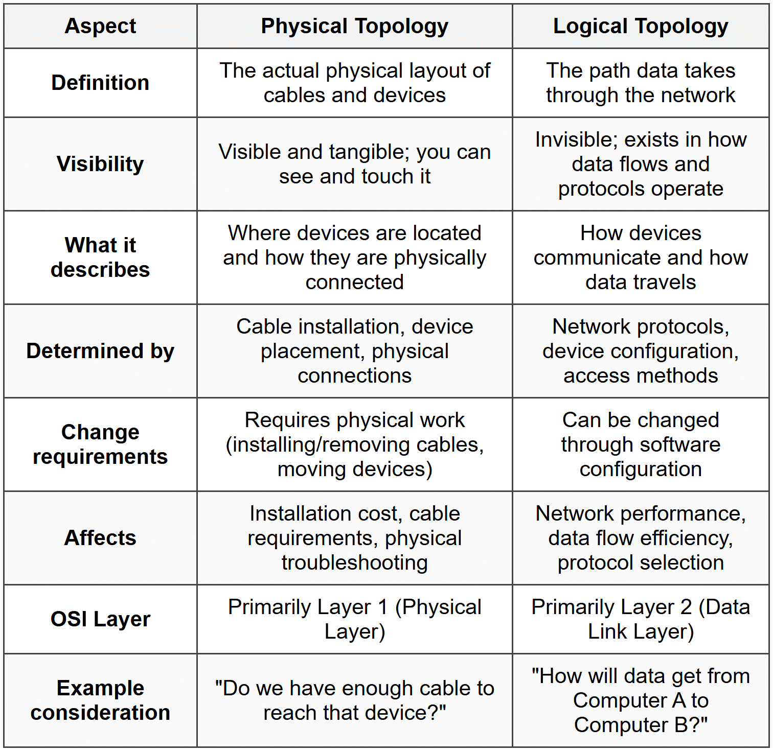
Key Differences Between Physical and Logical Topology
Now that we understand each concept individually, let's compare them directly to understand their differences clearly.
Why Physical and Logical Topologies Can Differ
One of the most important concepts to understand is that physical and logical topologies are independent of each other. A network can have one type of physical topology while using a completely different logical topology. This is not just possible-it's actually very common in modern networks.
How This Independence Works
The independence exists because:
- Hardware can be intelligent: Modern network devices like switches can receive data on one cable and make decisions about where to send it next, changing the logical path data takes.
- Protocols define behavior: The communication protocols determine how data flows, regardless of the physical cable arrangement.
- Configuration provides flexibility: Network administrators can configure devices to create different logical paths through the same physical infrastructure.
Think about a postal system. The physical topology is like the physical road network connecting houses and post offices. The logical topology is like the postal service's rules for routing mail. A letter from your house to your neighbor might physically travel along many roads to a central sorting facility and back, even though the houses are right next to each other. The physical layout (roads) hasn't changed, but the logical path (mail routing rules) determines where the letter actually goes.
Real-World Examples of Physical vs Logical Topology
Let's examine some concrete examples to solidify your understanding of how physical and logical topologies differ in practice.
Example 1: Traditional Ethernet Network with a Hub
Physical Topology: Star
Logical Topology: Bus
In this classic example, all computers have individual cables connecting to a central hub. When you look at the network, you see a star pattern with the hub in the center. However, a hub is a simple device that receives data on one port and broadcasts it to all other ports. Every computer receives every transmission, just like in a bus topology. Therefore:
- Physically, it's wired as a star (separate cables to a central point)
- Logically, it operates as a bus (all devices share the same communication channel)
Example 2: Modern Ethernet Network with a Switch
Physical Topology: Star
Logical Topology: Star
This looks identical to Example 1 physically-all computers connect with individual cables to a central switch. But a switch is intelligent. It learns which devices are on which ports and sends data only to the specific port where the destination device is connected. Therefore:
- Physically, it's wired as a star (separate cables to a central point)
- Logically, it operates as a star (data goes to the central switch, which forwards it only to the destination)
Example 3: Token Ring Network
Physical Topology: Star
Logical Topology: Ring
Token Ring networks (like IBM Token Ring) physically connect computers to a central device called an MAU (Multistation Access Unit). This looks like a star pattern. However, inside the MAU, the connections are wired to create a logical ring. Data passes from one computer to the next in a circular pattern, even though the physical cables all go to the center. Therefore:
- Physically, it's wired as a star (cables radiate from central MAU)
- Logically, it operates as a ring (data circulates in a loop through all devices)
Example 4: Wireless Network
Physical Topology: No physical connections (wireless)
Logical Topology: Star
In a wireless network, there are no physical cables connecting devices. However, all devices communicate through a central wireless access point (WAP). Data doesn't go directly from one laptop to another; it goes from the laptop to the access point, and then from the access point to the destination laptop. Therefore:
- Physically, there are no cables (wireless connections)
- Logically, it operates as a star (all communication passes through the access point)
Practical Implications for Network Design and Management
Understanding the distinction between physical and logical topology has important practical applications for anyone working with networks.
Network Design Considerations
When designing a network, you must consider both topologies:
- Physical topology decisions: Based on building layout, budget, cable availability, and ease of installation
- Logical topology decisions: Based on performance requirements, protocol standards, and how data should flow
The best approach is often to choose a flexible physical topology (like star) that can support different logical topologies as needs change.
Troubleshooting Networks
When problems occur, understanding both topologies helps you diagnose issues:
- Physical problems: Broken cables, disconnected devices, faulty network cards-these require understanding the physical topology
- Logical problems: Configuration errors, protocol conflicts, broadcast storms-these require understanding the logical topology
Example: If one computer cannot communicate with another, you might check the physical connection first (is the cable plugged in?), then check the logical configuration (is the switch configured correctly? Are the devices on the same network?).
Performance Optimization
Performance tuning often involves the logical topology:
- Changing from hubs to switches changes the logical topology from bus to star, improving performance
- Creating VLANs (Virtual LANs) creates logical segments without changing physical wiring
- Configuring spanning tree protocol affects the logical path data takes through redundant physical connections
Network Upgrades
One major advantage of understanding this distinction is upgrade flexibility:
- You can upgrade from a logical bus to a logical star by replacing hubs with switches, without rewiring
- You can implement new protocols that change logical topology without touching physical infrastructure
- You can reconfigure logical paths for redundancy while maintaining the same physical layout
The Role of Network Devices
Different network devices affect physical and logical topologies in different ways. Understanding these devices helps clarify the relationship between the two topology types.
Devices That Affect Physical Topology
- Cables: Define the physical connections and layout
- Connectors: Determine how devices physically attach to cables
- Patch panels: Organize physical cable terminations in equipment rooms
- Cable trays and conduits: Determine the physical path of cables through buildings
Devices That Affect Logical Topology
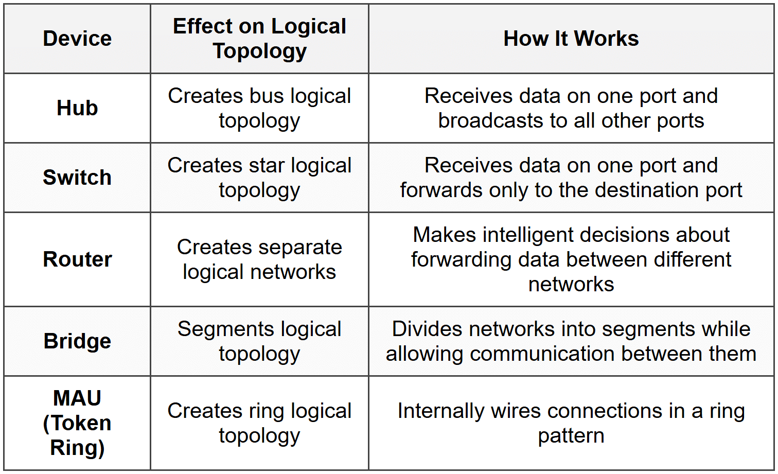
Devices That Affect Both
Some devices affect both physical and logical topologies:
- Switches: Define the physical star (where cables connect) and logical star (how data is forwarded)
- Wireless access points: Create the physical wireless infrastructure and central logical hub
Common Misconceptions
Let's address some frequent misunderstandings about physical and logical topologies:
Misconception 1: Physical and Logical Topologies Must Match
Reality: They are independent and often differ. Modern networks frequently use star physical topology with different logical topologies.
Misconception 2: Logical Topology Doesn't Matter for Small Networks
Reality: Even small networks have both physical and logical topologies. Understanding both helps with troubleshooting and performance, regardless of network size.
Misconception 3: Changing Physical Topology Always Changes Logical Topology
Reality: You can change physical layout (move devices, reorganize cables) without changing how data flows logically, as long as the same devices are used and configured the same way.
Misconception 4: Wireless Networks Don't Have Physical Topology
Reality: While they lack physical cables between devices, wireless networks still have physical components (access points, antennas) with a physical arrangement. The "physical topology" simply describes the wireless infrastructure layout rather than cable layout.
Misconception 5: Only Network Engineers Need to Understand This
Reality: Anyone who works with networks benefits from understanding both topologies. IT support staff, system administrators, and even end users who troubleshoot their own connectivity issues can use this knowledge.
Historical Context
Understanding how network topologies evolved helps explain why we have the current distinction between physical and logical topologies.
Early Networks
In early computer networks, physical and logical topologies were usually the same:
- Early Ethernet (10BASE5, 10BASE2): Used a bus physical topology with coaxial cable, and operated as a bus logically. All devices literally attached to the same cable.
- Simplicity: There was no intelligent device in the middle to change how data flowed.
The Introduction of Hubs
When hubs were introduced, we saw the first common divergence:
- Physical topology became star (easier to install and manage)
- Logical topology remained bus (hubs just repeated signals to all ports)
- This provided installation benefits without changing the fundamental network operation
The Switch Revolution
The introduction of switches changed the logical topology:
- Physical topology remained star (same cabling as hubs)
- Logical topology became star (switches intelligently forward data)
- This dramatically improved network performance without rewiring buildings
Modern Networks
Today's networks clearly separate physical and logical concerns:
- Physical infrastructure is designed for flexibility and ease of management
- Logical topology is determined by intelligent devices and software configuration
- Virtual networks (VLANs, VPNs) create logical topologies completely independent of physical layout
Advanced Concepts
VLANs and Virtual Topologies
VLANs (Virtual Local Area Networks) take the separation of physical and logical topology to an extreme. With VLANs, you can create multiple completely separate logical networks using the same physical infrastructure.
For example, in an office building:
- Physical topology: One star network with all devices connected to the same switches
- Logical topology: Multiple separate networks (one for sales, one for engineering, one for management) that cannot directly communicate with each other, even though they share the same physical switches and cables
Redundancy and Failover
Networks often have redundant physical paths for reliability. The active logical topology uses one set of paths, while backup paths exist physically but aren't used logically unless the primary paths fail.
- Physical topology: Mesh with multiple paths between devices
- Logical topology: Tree or star, with protocols like Spanning Tree Protocol (STP) blocking redundant paths to prevent loops, but ready to activate them if needed
Software-Defined Networking (SDN)
Modern Software-Defined Networking completely decouples physical and logical topologies. Network administrators can create, modify, and delete logical network paths through software, without touching physical infrastructure. The same physical network can support many different logical configurations simultaneously.
Summary
Let's recap the essential points about physical and logical topology:
- Physical topology describes the actual, tangible layout of network devices and cables-what you can see and touch.
- Logical topology describes how data actually flows through the network-the path data takes and how devices communicate.
- These two topologies are independent-a network can have one type of physical topology while using a different logical topology.
- Physical topology is determined by cable installation and device placement.
- Logical topology is determined by network protocols and device configuration.
- Common physical topologies include bus, star, ring, and mesh.
- Common logical topologies include bus, star, and ring.
- Network devices like hubs, switches, and routers affect the logical topology.
- Modern networks typically use star physical topology for flexibility and ease of management.
- Understanding both topologies is essential for network design, troubleshooting, and optimization.
Key Takeaway: Physical topology is about where things are and how they're connected. Logical topology is about how data flows and how devices communicate. Both are important, both are different, and understanding both gives you complete knowledge of how a network really works.
Review Questions
- What is the fundamental difference between physical topology and logical topology?
- Can a network have a star physical topology and a bus logical topology? If so, provide an example.
- Why is it important for network administrators to understand both physical and logical topologies?
- What network device creates a star physical topology but a bus logical topology, and how does it work?
- How does a switch differ from a hub in terms of logical topology?
- If you replace all the hubs in a network with switches but don't change any cables, which topology changes-physical, logical, or both? Explain.
- What are three factors that influence the choice of physical topology when designing a network?
- Describe how a Token Ring network demonstrates the difference between physical and logical topologies.
- Can you change a network's logical topology without changing its physical topology? Provide an example.
- Why do modern networks typically use star physical topology rather than bus or ring physical topologies?
- What role do network protocols play in determining logical topology?
- In troubleshooting, how would you determine whether a problem is related to physical topology or logical topology?
- What does it mean that physical and logical topologies are "independent" of each other?
- How do VLANs demonstrate the separation between physical and logical network organization?
- What is one advantage of having flexibility between physical and logical topologies when upgrading a network?
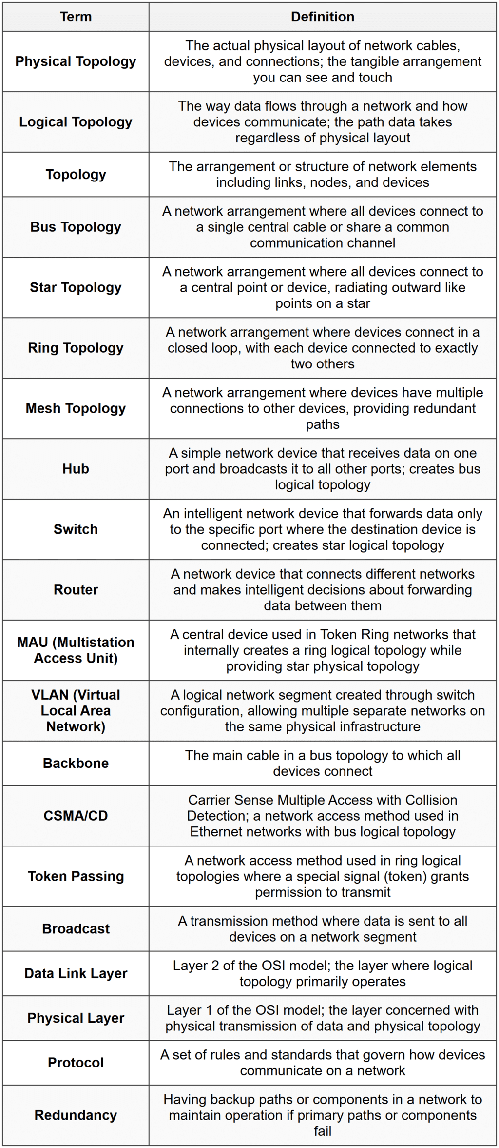
Glossary