Switching Methods & Frame Forwarding


Switching Methods & Frame Forwarding
When you send data across a network, it doesn't travel as one continuous stream. Instead, it's broken into small chunks called frames. Network switches are the devices responsible for receiving these frames and forwarding them to their correct destination. But how exactly does a switch decide when and how to forward a frame? This is where switching methods come into play.
In this study document, you'll learn about the different techniques switches use to process and forward frames, the advantages and disadvantages of each method, and how they impact network performance. Understanding these concepts is essential for anyone working with or studying computer networks.
What Is a Network Switch?
Before we dive into switching methods, let's make sure we understand what a switch actually does.
A network switch is a device that connects multiple devices (like computers, printers, and servers) within a local area network (LAN). When one device wants to send data to another, the switch receives the data frame and forwards it to the appropriate destination port.
Think of a switch like a postal worker at a sorting facility. When mail arrives, the worker reads the address on each envelope and places it in the correct bin for delivery. Similarly, a switch reads the destination address in each frame and forwards it to the correct port.
Switches operate primarily at Layer 2 of the OSI model (the Data Link Layer), though some advanced switches also operate at Layer 3. They use MAC addresses (Media Access Control addresses) to identify devices and make forwarding decisions.
Key Components of Switch Operation
- MAC Address Table: Also called a CAM table (Content Addressable Memory), this is a database the switch maintains that maps MAC addresses to specific ports.
- Ingress Port: The port where a frame enters the switch.
- Egress Port: The port where a frame exits the switch toward its destination.
- Frame Buffer: Temporary memory where frames are stored while being processed.
Understanding Frame Structure
To understand switching methods, you need to know what's inside a frame. A typical Ethernet frame consists of several fields:
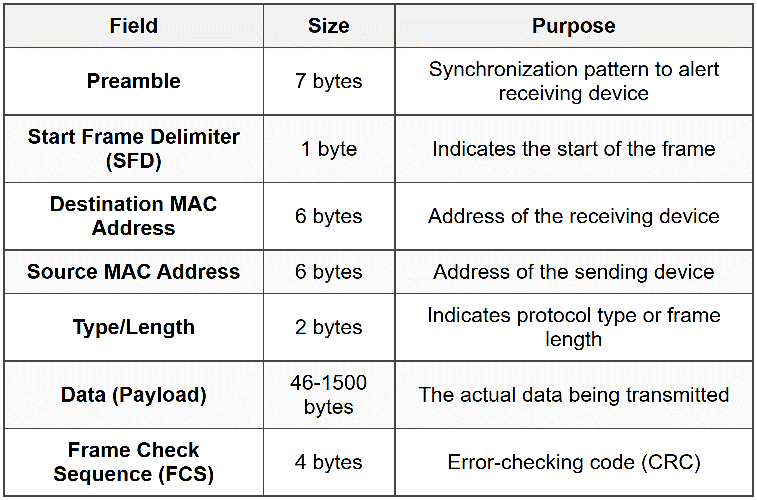
The Frame Check Sequence (FCS) is particularly important for switching methods. It's a cyclic redundancy check (CRC) value calculated based on the frame's contents. The receiving device recalculates this value to verify that the frame wasn't corrupted during transmission.
Important: Different switching methods read different amounts of the frame before making forwarding decisions. Some read only the destination address, while others read the entire frame including the FCS.
The Three Main Switching Methods
There are three primary methods switches use to forward frames:
- Store-and-Forward Switching
- Cut-Through Switching
- Fragment-Free Switching
Each method represents a different trade-off between speed and error checking. Let's examine each one in detail.
Store-and-Forward Switching
Store-and-forward switching is the most reliable and thorough switching method. In this approach, the switch receives and stores the entire frame in its buffer before making any forwarding decision.
How Store-and-Forward Works
- The switch receives the incoming frame on an ingress port.
- The entire frame is stored in the switch's memory buffer.
- The switch performs a CRC check by verifying the Frame Check Sequence (FCS).
- If the frame passes the error check, the switch reads the destination MAC address.
- The switch looks up the destination MAC address in its MAC address table.
- The frame is forwarded out the appropriate egress port.
- If the frame fails the error check, it is discarded.
Imagine a quality control inspector at a factory who examines every product completely before allowing it to ship. This is like store-and-forward-the switch inspects the entire frame for errors before forwarding it.
Advantages of Store-and-Forward
- Error Detection: The switch checks for errors and discards corrupted frames, preventing bad data from propagating through the network.
- Network Reliability: Only valid frames are forwarded, improving overall network quality.
- Automatic Buffering: Can handle frames arriving on ports with different speeds (e.g., 100 Mbps to 1 Gbps).
- Standards Compliance: Enforces minimum and maximum frame size requirements.
Disadvantages of Store-and-Forward
- Higher Latency: The switch must receive the entire frame before forwarding, which introduces delay.
- Variable Delay: Larger frames take longer to receive completely, so latency varies with frame size.
Latency Calculation
The latency in store-and-forward switching depends on the frame size and the port speed. The time to receive a frame can be calculated as:
\[ \text{Receive Time} = \frac{\text{Frame Size (bits)}}{\text{Port Speed (bits per second)}} \]Where:
- Frame Size is measured in bits
- Port Speed is the transmission rate in bits per second (bps)
Example:
A 1500-byte frame on a 100 Mbps port:
Frame size = 1500 bytes × 8 bits/byte = 12,000 bits
Port speed = 100,000,000 bps
Receive time = 12,000 ÷ 100,000,000 = 0.00012 seconds = 120 microseconds
When Store-and-Forward Is Used
Store-and-forward is the default method for most modern switches, especially:
- Enterprise-grade switches
- Switches connecting networks with different speeds
- Environments where data integrity is critical
- Networks requiring quality of service (QoS) features
Cut-Through Switching
Cut-through switching is the fastest switching method. Instead of waiting for the entire frame, the switch begins forwarding as soon as it reads the destination MAC address.
How Cut-Through Works
- The switch begins receiving the frame on an ingress port.
- The switch reads only the first 14 bytes (destination MAC, source MAC, and type/length fields).
- As soon as the destination MAC address is read, the switch looks it up in the MAC address table.
- The switch immediately begins forwarding the frame out the appropriate egress port.
- The rest of the frame is forwarded as it arrives, without buffering.
- No error checking is performed on the frame.
Think of an express courier service that starts delivering a package as soon as they read the address label, without inspecting the contents. Cut-through switching works the same way-it forwards immediately based on the destination address alone.
Advantages of Cut-Through
- Low Latency: Minimal delay since forwarding begins almost immediately.
- Fixed Delay: Latency is consistent regardless of frame size.
- High Performance: Ideal for time-sensitive applications like voice or video.
Disadvantages of Cut-Through
- No Error Detection: Corrupted frames are forwarded along with valid ones.
- Network Pollution: Bad frames propagate through the network, wasting bandwidth.
- Speed Limitation: Both ingress and egress ports must operate at the same speed.
- No Buffering: Cannot accommodate speed mismatches between ports.
Latency in Cut-Through Switching
The latency is essentially the time required to read the destination MAC address (first 14 bytes of the frame header):
\[ \text{Cut-Through Latency} = \frac{112 \text{ bits}}{\text{Port Speed (bps)}} \]Where:
- 112 bits = 14 bytes (destination MAC + source MAC + type field)
- Port Speed is in bits per second
Example:
On a 1 Gbps port:
Latency = 112 bits ÷ 1,000,000,000 bps = 0.000000112 seconds = 0.112 microseconds
When Cut-Through Is Used
- High-performance computing environments
- Low-latency trading systems
- Real-time applications
- Networks with generally clean, error-free transmission media
Note: Many modern switches that support cut-through can automatically fall back to store-and-forward if they detect a high error rate on the network. This is called adaptive switching.
Fragment-Free Switching
Fragment-free switching is a compromise between store-and-forward and cut-through. It's sometimes called runt-free switching or modified cut-through.
Understanding Frame Fragments and Collisions
In traditional Ethernet networks using hubs and shared media, collisions could occur when two devices transmitted simultaneously. Most collisions are detected within the first 64 bytes of a frame. A frame smaller than 64 bytes is considered a runt frame or collision fragment and is invalid.
Fragment-free switching addresses this by reading the first 64 bytes before forwarding.
How Fragment-Free Works
- The switch receives the incoming frame.
- The switch reads and buffers the first 64 bytes of the frame.
- This ensures the frame is not a collision fragment.
- Once 64 bytes are received, the switch looks up the destination MAC address.
- The switch begins forwarding the frame out the appropriate port.
- The rest of the frame is forwarded as it arrives.
Imagine a security checkpoint that inspects the first portion of every package to ensure it meets minimum safety standards, then lets it through without a full inspection. Fragment-free switching performs this basic check before forwarding.
Advantages of Fragment-Free
- Filters Collision Fragments: Prevents most error frames (runts) from propagating.
- Lower Latency than Store-and-Forward: Doesn't wait for the entire frame.
- Better than Cut-Through: Catches the most common frame errors.
Disadvantages of Fragment-Free
- Incomplete Error Detection: Errors in the rest of the frame (beyond 64 bytes) are not detected.
- Still Forwards Some Bad Frames: Frames with errors after byte 64 still get forwarded.
- Higher Latency than Cut-Through: Must wait for 64 bytes before forwarding.
Latency in Fragment-Free Switching
The latency depends on the time to receive the first 64 bytes:
\[ \text{Fragment-Free Latency} = \frac{512 \text{ bits}}{\text{Port Speed (bps)}} \]Where:
- 512 bits = 64 bytes (minimum frame size to check)
- Port Speed is in bits per second
Example:
On a 100 Mbps port:
Latency = 512 bits ÷ 100,000,000 bps = 0.00000512 seconds = 5.12 microseconds
When Fragment-Free Is Used
- Networks transitioning from hubs to switches
- Environments where collision fragments were historically a problem
- As a middle ground when store-and-forward is too slow but cut-through is too risky
Important: In modern switched networks with full-duplex connections, collisions don't occur, making fragment-free switching less relevant. Most contemporary networks use store-and-forward exclusively.
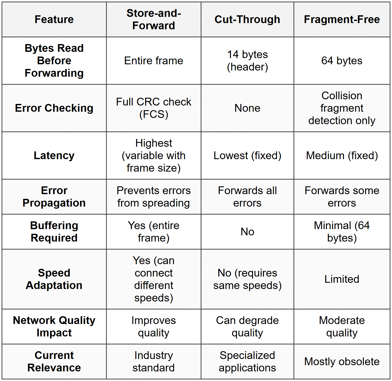
Comparison of Switching Methods
Let's summarize the key differences among the three switching methods:
Frame Forwarding Decision Process
Regardless of the switching method used, every switch must make a forwarding decision for each frame it receives. This decision is based on the switch's MAC address table.
How the MAC Address Table Works
The MAC address table (also called the CAM table or switching table) is a dynamic database that maps MAC addresses to switch ports. The switch builds and maintains this table automatically through a process called learning.
The Learning Process
- When a frame arrives on a port, the switch reads the source MAC address.
- The switch adds an entry to its MAC address table: "This MAC address is reachable via this port."
- Each entry includes a timestamp.
- If a device doesn't send any traffic for a period (typically 300 seconds or 5 minutes), its entry ages out and is removed.
- This process happens continuously and automatically.
Think of the MAC address table like a phone directory that updates itself. Each time someone calls you, the directory notes their number and which line they called from. If someone doesn't call for months, their entry is eventually removed to keep the directory current.
Three Types of Frame Forwarding
When a switch receives a frame, it examines the destination MAC address and takes one of three actions:
1. Unicast Forwarding (Known Destination)
If the destination MAC address exists in the MAC address table:
- The switch looks up the destination MAC address in its table.
- It finds the associated egress port.
- The frame is forwarded only out that specific port.
- This is the most efficient type of forwarding.
2. Flooding (Unknown Destination)
If the destination MAC address is not in the MAC address table:
- The switch doesn't know which port leads to the destination.
- The frame is forwarded out all ports except the ingress port (where it arrived).
- This is called flooding or an unknown unicast flood.
- When the destination device responds, the switch learns its location and updates the table.
Note: Flooding is normal behavior, not an error. It ensures the frame reaches its destination even when the switch hasn't yet learned the destination's location.
3. Broadcasting
If the destination MAC address is the broadcast address (FF:FF:FF:FF:FF:FF):
- The frame is intended for all devices on the network.
- The switch forwards the frame out all ports except the ingress port.
- Every device on the local network receives the broadcast frame.
Common broadcast uses:
- ARP (Address Resolution Protocol) requests
- DHCP (Dynamic Host Configuration Protocol) discovery
- Network announcements
Forwarding Decision Flowchart
Here's the logical process a switch follows:
- Receive frame on ingress port
- Learn source MAC address → Update MAC address table
- Examine destination MAC address
- Decision:
- If destination = broadcast address → Flood to all ports (except ingress)
- If destination in MAC table → Forward to specific egress port
- If destination not in MAC table → Flood to all ports (except ingress)
- If destination = source port → Filter (drop the frame)
Frame Filtering and Forwarding Optimization
Beyond basic forwarding, switches perform additional operations to optimize network performance.
Frame Filtering
Filtering occurs when a switch receives a frame destined for a device on the same port where the frame arrived. In this case:
- The switch drops the frame rather than forwarding it.
- This is because the frame has already reached the local network segment.
- Filtering prevents unnecessary traffic and loops.
Imagine a mail carrier who picks up a letter from your mailbox addressed to your neighbor next door. Instead of taking it to the post office for processing, the carrier simply walks it directly to your neighbor. That's filtering-the switch realizes the frame doesn't need to go anywhere else.
Microsegmentation
Microsegmentation is a key benefit of switching. Each switch port creates its own collision domain, meaning:
- Devices on different ports can communicate simultaneously without collisions.
- Each connection gets dedicated bandwidth.
- Network performance improves dramatically compared to hubs.
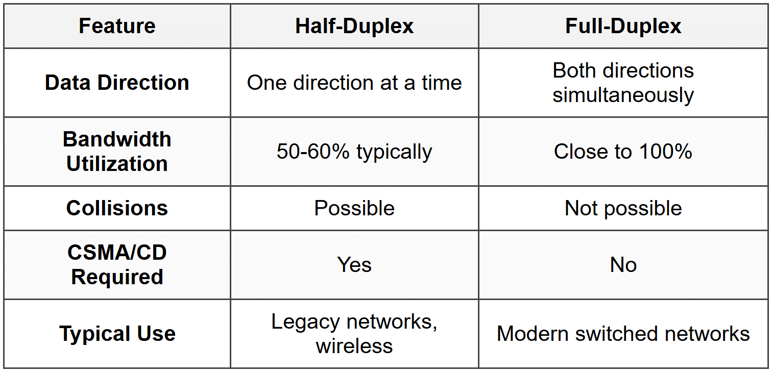
Full-Duplex Operation
Modern switches support full-duplex communication:
- Devices can send and receive data simultaneously.
- Effectively doubles the bandwidth (e.g., 100 Mbps becomes 100 Mbps in each direction).
- Eliminates collisions entirely on point-to-point links.
- No need for CSMA/CD (Carrier Sense Multiple Access with Collision Detection).
Switch Latency and Performance Metrics
Understanding switch performance involves several key metrics beyond just the switching method.
Types of Latency
Latency is the time delay from when a frame enters a switch until it exits. Several factors contribute to total latency:
- Propagation Delay: Time for electrical signals to travel through cables (minimal in LANs).
- Serialization Delay: Time to place bits onto the wire at a given speed.
- Processing Delay: Time for the switch to make forwarding decisions.
- Queuing Delay: Time a frame waits in a buffer when the egress port is busy.
Switching Method Impact on Latency
Different switching methods have dramatically different latency characteristics:
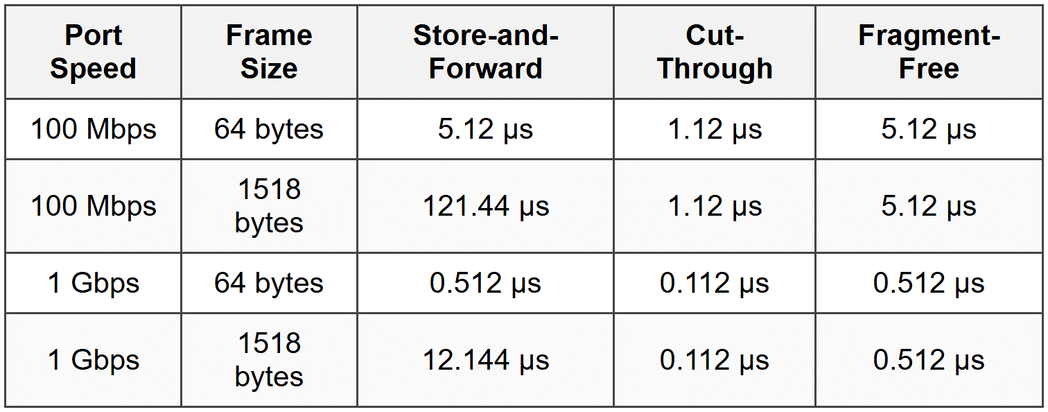
Where μs = microseconds (millionths of a second)
Throughput
Throughput is the amount of data the switch can successfully forward per unit of time. It's measured in:
- Bits per second (bps): e.g., 1 Gbps, 10 Gbps
- Frames per second (fps): Number of frames processed
- Packets per second (pps): For Layer 3 switches
Backplane Bandwidth
The backplane or switching fabric is the internal connection within a switch that carries data between ports. Its bandwidth determines the switch's maximum capacity:
\[ \text{Required Backplane Bandwidth} = \sum (\text{Port Speed} \times 2) \]The factor of 2 accounts for full-duplex operation (traffic in both directions).
Example:
A 24-port switch with all 1 Gbps ports:
Required bandwidth = 24 ports × 1 Gbps × 2 = 48 Gbps backplane bandwidth
Wire-Speed Switching
A switch achieves wire-speed performance when it can forward frames at the maximum rate of its ports without dropping frames due to processing limitations.
Important: Wire-speed capability is independent of the switching method used. Store-and-forward switches can operate at wire-speed if they have sufficient processing power and memory.
Error Handling and Frame Validation
How switches handle errors depends on the switching method and the type of error detected.
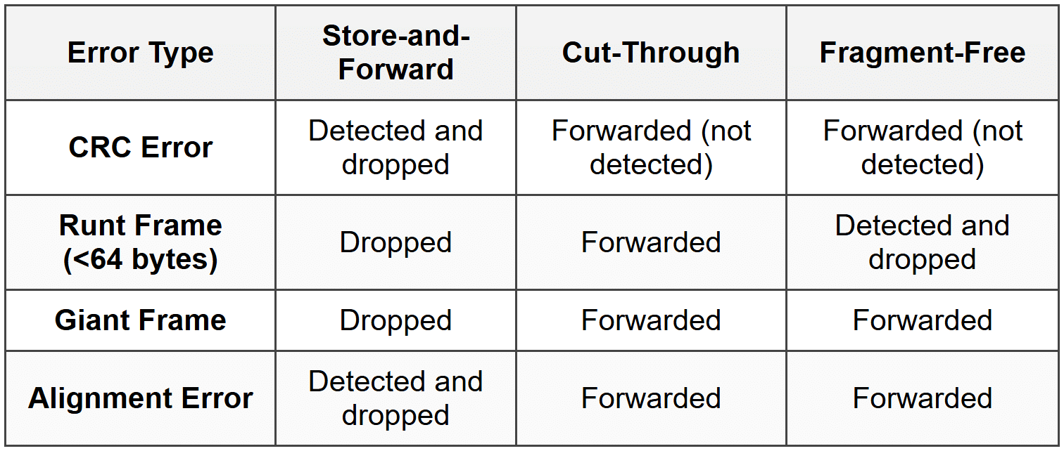
Types of Frame Errors
- CRC Errors: Frame Check Sequence doesn't match calculated value (data corruption).
- Runt Frames: Frames smaller than 64 bytes (often collision fragments).
- Giant Frames: Frames larger than the maximum allowed size (1518 bytes for standard Ethernet, 1522 for VLAN-tagged).
- Jabber: A device continuously transmitting garbage data.
- Alignment Errors: Frame doesn't end on a byte boundary.
Error Handling by Switching Method
Error Statistics and Monitoring
Switches maintain error counters for each port, tracking:
- CRC errors
- Runt frames
- Giant frames
- Collisions (in half-duplex mode)
- Dropped frames
Network administrators monitor these statistics to identify problems like faulty cables, malfunctioning network adapters, or electromagnetic interference.
Adaptive Switching and Auto-Negotiation
Adaptive Switching
Some advanced switches implement adaptive switching or automatic switching mode selection:
- The switch normally operates in cut-through mode for low latency.
- It monitors the error rate on the network.
- If errors exceed a threshold, the switch automatically falls back to store-and-forward mode.
- When the error rate drops, it returns to cut-through mode.
This provides the best of both worlds: low latency when the network is clean, and error filtering when problems arise.
Auto-Negotiation
Auto-negotiation is a mechanism that allows devices to automatically configure optimal connection parameters:
- Speed: 10 Mbps, 100 Mbps, 1 Gbps, 10 Gbps, etc.
- Duplex mode: Half-duplex or full-duplex
When two devices connect, they exchange information about their capabilities and select the highest common performance level.
Warning: Duplex mismatches (one side configured for full-duplex, the other for half-duplex) cause severe performance problems including excessive collisions, CRC errors, and slow throughput. Always verify duplex settings match on both ends of a connection.
VLANs and Frame Forwarding
While VLANs (Virtual Local Area Networks) are a broader topic, they affect frame forwarding behavior.
VLAN Basics
A VLAN is a logical grouping of devices that creates a separate broadcast domain, even if devices are connected to the same physical switch.
- Frames are tagged with a VLAN ID (802.1Q standard).
- Switches forward frames only to ports in the same VLAN.
- Broadcast frames are flooded only within the same VLAN.
Impact on Switching Methods
VLANs don't fundamentally change the switching method, but they add complexity:
- The switch must read the VLAN tag (if present) in addition to MAC addresses.
- The MAC address table includes VLAN information (MAC address + VLAN ID + port).
- Forwarding decisions consider both MAC address and VLAN membership.
Practical Considerations and Best Practices
Choosing a Switching Method
In practice, most network administrators don't choose a switching method-modern switches use store-and-forward by default. However, understanding the options helps in specific scenarios:
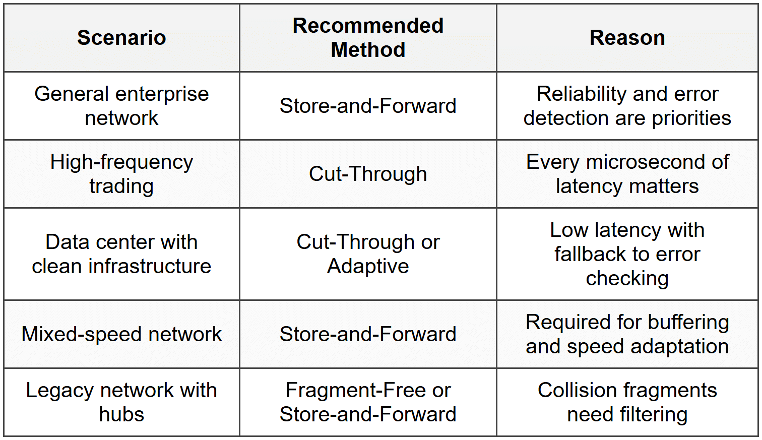
Network Design Considerations
- Use full-duplex wherever possible: Eliminates collisions and doubles bandwidth.
- Monitor error rates: High error rates indicate physical layer problems that no switching method can fix.
- Avoid speed mismatches: Connect devices of similar speeds to avoid buffering delays.
- Segment networks with VLANs: Reduces broadcast traffic and improves security.
- Size switch buffers appropriately: Larger buffers help in high-traffic scenarios but increase cost.
Troubleshooting Frame Forwarding Issues
Common problems and solutions:
- Problem: Slow performance despite adequate bandwidth
- Check: Duplex settings (look for duplex mismatch)
- Check: Error counters (high CRC or collision counts)
- Problem: Devices can't communicate
- Check: VLAN configuration
- Check: MAC address table for learned addresses
- Check: Port status (up/down)
- Problem: Intermittent connectivity
- Check: Cable quality and connections
- Check: Switch port errors
- Check: MAC address table stability (flapping)
Advanced Topics and Modern Developments
Software-Defined Networking (SDN)
In SDN environments, frame forwarding decisions can be controlled by a central controller rather than individual switch logic:
- The controller programs flow tables into switches.
- Switches consult these tables for forwarding decisions.
- Allows for more sophisticated, network-wide forwarding policies.
- The underlying switching method (store-and-forward, etc.) still applies at the physical layer.
Data Center Bridging (DCB)
DCB is a set of enhancements to Ethernet for data center environments:
- Priority-based flow control: Prevents frame loss in specific traffic classes.
- Enhanced transmission selection: Bandwidth allocation across traffic types.
- Congestion notification: Signals switches to slow transmission before dropping frames.
These features build on traditional switching methods but add quality of service and lossless operation.
Cut-Through in Modern Data Centers
High-performance data centers increasingly use cut-through switching for:
- Storage networks requiring ultra-low latency
- High-frequency communication between servers
- Distributed computing applications sensitive to latency jitter
Modern implementations include:
- Adaptive cut-through: Automatic fallback to store-and-forward when errors are detected
- Per-flow switching mode: Different flows can use different methods simultaneously
- Intelligent error handling: Logging errors even when not checking FCS
Review Questions
- What is the primary difference between store-and-forward and cut-through switching in terms of when forwarding begins?
- Why does store-and-forward switching have variable latency while cut-through has fixed latency?
- A network switch receives a frame with a destination MAC address that is not in its MAC address table. What action does the switch take?
- What type of error does fragment-free switching detect that cut-through switching does not?
- Calculate the time required to receive a complete 1518-byte frame on a 1 Gbps port. Show your work.
- Why is cut-through switching unable to connect ports operating at different speeds (e.g., 100 Mbps to 1 Gbps)?
- What is the purpose of the Frame Check Sequence (FCS) field in an Ethernet frame?
- Explain how a switch builds its MAC address table. What information does it learn from incoming frames?
- In what situation would a network administrator prefer cut-through switching over store-and-forward switching despite the lack of error checking?
- What is the main advantage that fragment-free switching historically provided in networks with hubs?
- If a switch operates in full-duplex mode, what happens to collision detection, and why?
- Why do modern enterprise networks predominantly use store-and-forward switching as the default method?
- What is adaptive switching, and what problem does it solve?
- Describe what happens when a switch receives a frame with the destination MAC address FF:FF:FF:FF:FF:FF.
- What is microsegmentation, and how does switching enable it?
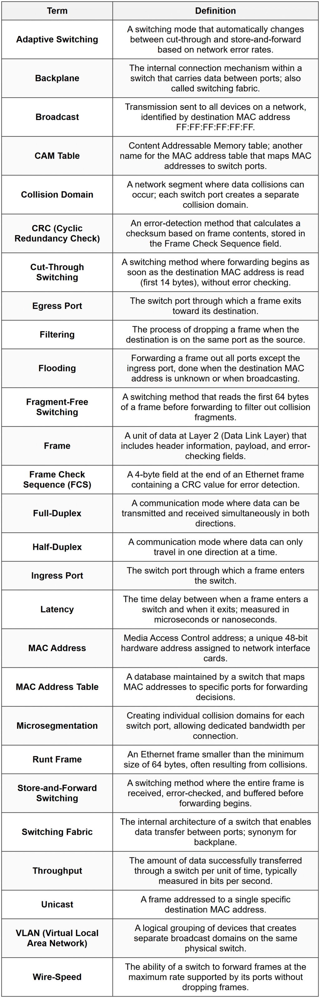
Glossary