Assignment : Textures


Section 1: Multiple Choice Questions
- Q1. You are working on a 3D model of a brick wall and need to add surface detail without increasing polygon count. Which texture type would be most appropriate to simulate the raised mortar lines between bricks?
- Diffuse texture only
- Normal map combined with base color texture
- Emission texture
- Transparency texture
- Q2. When unwrapping a cylindrical object like a water bottle in Blender, which UV unwrapping method would minimize distortion while keeping the label area as a single, rectangular UV island?
- Smart UV Project
- Cube Projection
- Cylinder Projection
- Sphere Projection
- Q3. A student notices that their metallic texture appears too bright and unrealistic in the render. The roughness value is set to 0.1 and the metallic value is set to 1.0. What is the most likely cause of the unrealistic appearance?
- The metallic value should be set to 0.5
- The object lacks proper environment lighting or HDRI for realistic reflections
- The roughness value is too high
- The base color is incorrect
- Q4. You want to create a texture that makes certain parts of a glass object completely transparent while other parts remain opaque. Which shader node input in the Principled BSDF would you primarily use?
- Transmission
- Alpha
- Clearcoat
- Specular
- Q5. When baking textures in Blender, you need to transfer detail from a high-resolution mesh to a low-resolution game model. Which baking type would capture the surface detail and lighting information most effectively?
- Diffuse bake only
- Combined bake with all lighting
- Normal map bake from the high-res to low-res mesh
- Emission bake
Section 2: Conceptual Questions
- Q1. Explain the difference between procedural textures and image textures in Blender. Provide one advantage and one disadvantage of each approach.
- Q2. Describe what UV mapping is and why it is necessary for applying image textures to 3D models. What happens if a model is not UV unwrapped before applying an image texture?
- Q3. In the Principled BSDF shader, explain the role of the Roughness parameter and how it affects the appearance of both metallic and non-metallic materials.
Section 3: Node Setup Analysis
Task 1: Examine the following shader node setup description and answer the questions below.
Image Texture Node (brick_color.png) └─> Color output connected to Base Color input of Principled BSDF Image Texture Node (brick_normal.png) [Color Space: Non-Color] └─> Color output connected to Normal Map Node └─> Normal output connected to Normal input of Principled BSDF Image Texture Node (brick_roughness.png) [Color Space: Non-Color] └─> Color output connected to Roughness input of Principled BSDF
Questions:
- What is the purpose of setting the Color Space to "Non-Color" for the normal and roughness texture nodes?
- Why must the normal texture pass through a Normal Map node before connecting to the Principled BSDF?
- If the rendered material appears flat despite having a normal map connected, what are two possible causes?
Task 2: A user wants to create a glowing neon sign. They set up the following:
Image Texture Node (neon_text.png) └─> Color output connected to Emission input of Principled BSDF └─> Alpha output connected to Alpha input of Principled BSDF Emission Strength: 5.0
Questions:
- Will this setup produce a glowing effect in the Eevee render engine? What additional setting might need to be enabled?
- Explain what the Alpha connection accomplishes in this setup.
- How would you increase the intensity of the glow effect surrounding the neon sign?
Section 4: Practical Application Tasks
- Q1. Create a complete node-based material setup for a wooden table surface. Your setup must include:
- A base color texture for the wood grain
- A normal map to simulate wood grain depth
- Appropriate roughness settings for a polished wood finish
- Proper color space settings for each texture node
Describe the complete node connections and parameter values you would use.
- Q2. You have created a character model and need to prepare it for texture painting. Outline the complete workflow from an un-unwrapped model to being ready for texture painting in Texture Paint mode. Include:
- UV unwrapping steps and seam placement considerations
- Creating and assigning a new image texture
- Setting up the material nodes
- Switching to Texture Paint workspace
- Q3. A product visualization requires a brushed metal texture with visible directional scratches. Describe how you would create this material using a combination of:
- Metallic and roughness values in the Principled BSDF
- An anisotropic texture approach or procedural method
- Proper lighting setup to showcase the material effectively
Provide specific parameter values and explain your choices.
- Q4. You need to create a seamless tileable texture for a large floor surface. The texture is a 2K image but the floor is much larger. Explain:
- How to set up the texture coordinates to control tiling frequency
- What UV mapping method would be appropriate for a flat floor plane
- How to verify the texture is seamless and adjust if visible seams appear
- How to add subtle variation to avoid obvious repetition
Section 5: Challenge Problem (Optional)
Advanced Material Creation: Weathered Painted Metal
Create a complex material that simulates painted metal that has weathered over time, showing areas where paint has chipped away to reveal bare metal underneath. Your material must demonstrate:
- Use of a mask texture or procedural method to control where paint appears versus bare metal
- Different roughness values for painted areas (slightly rough) versus metal areas (more reflective)
- Edge wear using geometry-based masking or texture-based approach
- Subtle color variation in the painted areas
- Rust or dirt accumulation in recessed areas (bonus)
Deliverable: Provide a complete node graph description showing all nodes, their connections, and parameter settings. Explain the logic behind your layering approach and how each element contributes to the final weathered appearance.
Constraints:
- Must use the Principled BSDF as the primary shader
- May combine procedural and image textures
- Should use Mix nodes or ColorRamp nodes to blend between paint and metal properties
- Must be physically plausible for realistic rendering
Answer Key
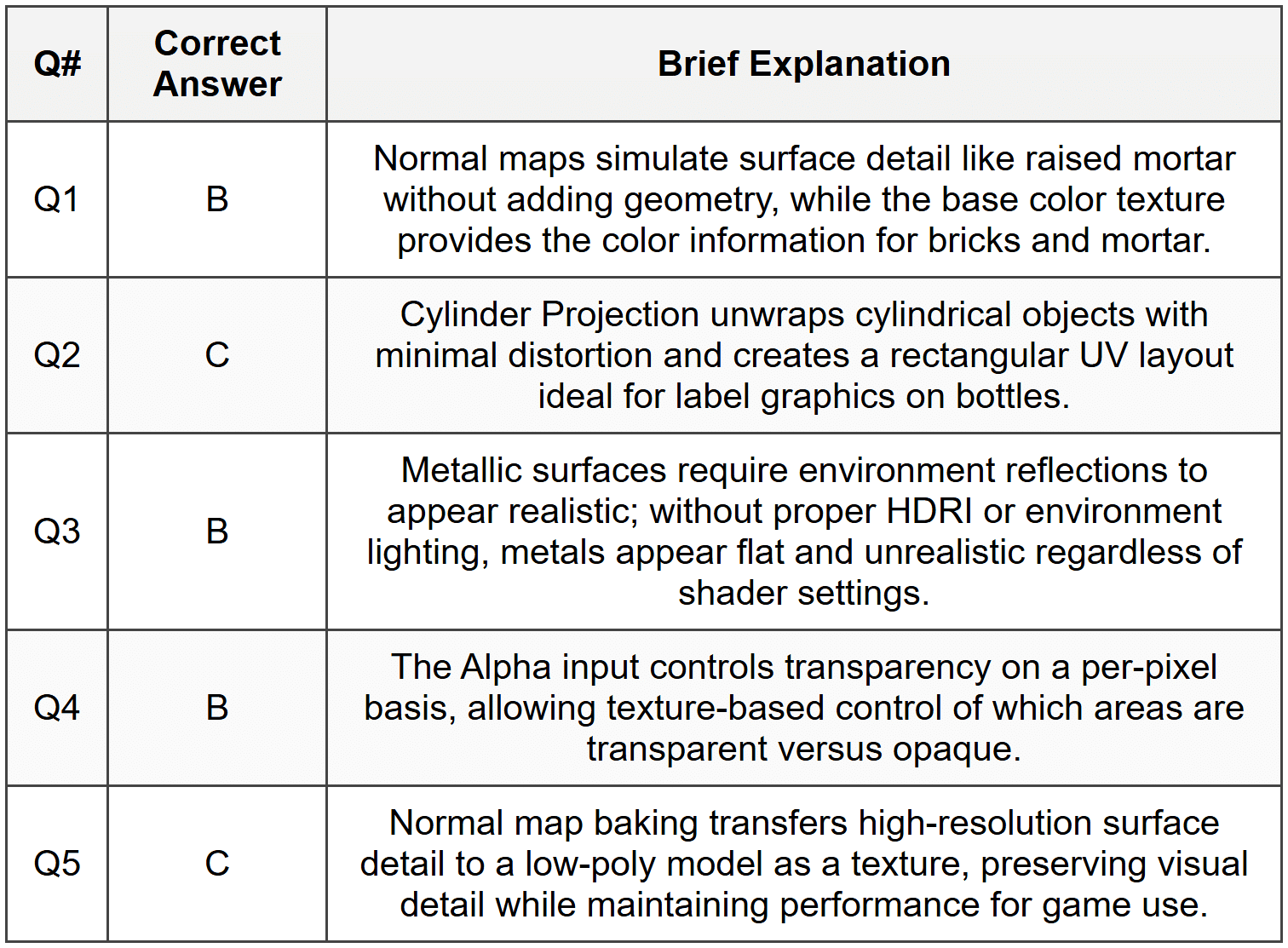
Section 1 - MCQ Answers
Section 2 Answers
Q1 Answer: Procedural textures are generated mathematically within Blender using nodes like Noise, Voronoi, or Musgrave. An advantage is that they are resolution-independent and never pixelate regardless of how close the camera gets. A disadvantage is that they can be less controllable and harder to achieve specific artistic looks compared to painted textures. Image textures are external files (PNG, JPG, etc.) that are mapped onto surfaces. An advantage is complete artistic control and the ability to create any specific pattern or design. A disadvantage is that they have fixed resolution and can appear pixelated when viewed too closely or stretched across large surfaces.
Q2 Answer: UV mapping is the process of unwrapping a 3D model's surface into a flat 2D representation, creating a correspondence between 3D surface points and 2D texture coordinates. It is necessary because image textures are 2D files, and Blender needs to know how to project these 2D images onto the 3D surface. Without UV unwrapping, Blender will use default coordinates that often result in stretched, distorted, or incorrectly positioned textures. The UV map acts like a pattern for wrapping paper around an object, telling Blender exactly which part of the texture image should appear on which part of the 3D model.
Q3 Answer: The Roughness parameter in the Principled BSDF controls how smooth or rough a surface appears by affecting how light scatters when reflecting off the material. A roughness value of 0.0 creates a perfect mirror-like reflection with sharp, clear reflections. Higher roughness values (up to 1.0) scatter reflected light more, creating blurrier, more diffuse reflections. For metallic materials, roughness determines whether the metal appears polished (low roughness) or brushed/oxidized (high roughness). For non-metallic materials, it controls the sharpness of specular highlights, with low roughness creating shiny plastics or glossy surfaces and high roughness creating matte surfaces like concrete or fabric.
Section 3 Answers
Task 1 Answers:
Color Space Question: Setting Color Space to "Non-Color" prevents Blender from applying color management transformations to data textures. Normal maps and roughness maps contain directional or numerical data, not actual colors meant for display. If interpreted as color data, Blender would apply gamma correction and color space conversions that would corrupt the data values, resulting in incorrect normals or roughness behavior.
Normal Map Node Question: The Normal Map node is required because normal map images store directional information in a tangent space format (the RGB values represent XYZ direction vectors). The Normal Map node interprets these color values correctly and converts them into actual normal vector data that the shader can use. Without this node, the shader would interpret the pretty blue-purple colors as actual colors rather than directional information.
Flat Appearance Causes: Two possible causes are: (1) The normal map strength might be set too low in the Normal Map node (default is 1.0; if reduced to near 0, it has no effect). (2) The lighting in the scene might be too flat or ambient; normal maps rely on directional lighting to show their effect, so insufficient or purely ambient lighting will not reveal the surface detail captured in the normal map.
Task 2 Answers:
Eevee Glow Question: This setup will produce emission, but to see a visible bloom/glow effect in Eevee, you must enable Bloom in the Render Properties panel. Emission alone makes the surface bright, but the Bloom post-processing effect creates the glowing halo around bright areas that makes neon signs appear to glow convincingly.
Alpha Connection: The Alpha connection makes parts of the material transparent based on the alpha channel of the texture. This allows the neon sign texture to have the text or shapes emit light while the surrounding areas remain completely invisible, so only the actual neon elements appear rather than a glowing rectangle.
Increasing Glow Intensity: To increase the glow effect, you can: increase the Emission Strength value beyond 5.0 (higher values create stronger bloom); increase the Bloom Intensity setting in Render Properties; or decrease the Bloom Threshold to make the glow affect a larger area around the bright emission source.
Section 4 Answers
Q1 Answer:
Complete wooden table material setup:
Image Texture Node 1 (wood_color.png):
Color Space: sRGB
Color output → Base Color of Principled BSDF
Image Texture Node 2 (wood_normal.png):
Color Space: Non-Color
Color output → Color input of Normal Map node
Normal Map node Strength: 1.0
Normal Map node Normal output → Normal input of Principled BSDF
Image Texture Node 3 (wood_roughness.png):
Color Space: Non-Color
Color output → Roughness input of Principled BSDF
Principled BSDF Settings:
Metallic: 0.0 (wood is non-metallic)
Roughness: controlled by texture (or base value 0.3-0.5 for polished wood if no texture)
Specular: 0.5 (default)
Clearcoat: 0.2-0.5 (optional, adds glossy finish layer for polished table)
Clearcoat Roughness: 0.1 (for subtle glossy finish)
The clearcoat parameters simulate a protective varnish or polish layer common on wooden furniture.
Q2 Answer:
Complete workflow for texture painting preparation:
Step 1 - UV Unwrapping:
Enter Edit Mode (Tab). Strategically place seams along edges where cuts would be least visible (underside of arms, back of head, inside of legs). Select edges and press Ctrl+E → Mark Seam. Select all faces (A) and press U → Unwrap. Switch to UV Editor to verify unwrap quality and minimal stretching. Arrange UV islands efficiently within the 0-1 texture space.
Step 2 - Create Image Texture:
In UV Editor, click Image → New Image. Set resolution (2048×2048 or 4096×4096 for characters). Choose color (typically neutral gray or white). Name the image appropriately. Ensure "Generated Type" is set to Blank or UV Grid for testing.
Step 3 - Material Setup:
Switch to Shading workspace. Create new material for the object. Add Image Texture node. Select the newly created image in the node. Connect Image Texture Color output to Base Color of Principled BSDF. This connection is essential for texture painting to work.
Step 4 - Enter Texture Paint Mode:
Switch to Texture Paint workspace or select Texture Paint mode from mode dropdown. In the header, ensure the correct image texture is selected as the active paint texture. Select a brush and begin painting directly on the 3D model. Changes appear in real-time both on the model and in the UV Editor.
Q3 Answer:
Brushed metal material creation:
Base Material Settings:
Principled BSDF Metallic: 1.0 (full metal)
Base Color: slight tint (RGB 0.9, 0.9, 0.95 for steel, or warmer for brass/copper)
Base Roughness: 0.3
Anisotropic Approach:
Set Anisotropic value: 0.7-0.9 (creates directional reflection stretching)
Add Texture Coordinate node → Object output
Add Mapping node to control rotation
Rotate to align scratches with desired direction (typically rotating Z axis by 90° for vertical brushing)
Connect to Vector input of a Noise Texture or Scratch texture
Use this texture to slightly modulate Anisotropic Rotation (0-1 value)
Also connect (via ColorRamp for contrast) to Roughness to create variation in scratch brightness
Alternative Procedural Method:
Use Wave Texture set to Bands, Direction Y (or X for horizontal)
Scale: 50-100 for fine lines
Add Noise Texture with high scale (500+) and low detail
Mix both textures using Color Mix node in Overlay or Add mode
Pass through ColorRamp to increase contrast
Connect to Roughness input (invert if needed so scratches are more reflective)
Lighting Setup:
Use HDRI environment with strong directional components or add Area Light at grazing angle (10-20° to surface). This reveals anisotropic reflections. Add second fill light from opposite side at lower intensity. The directional lighting is crucial as it creates the linear highlights characteristic of brushed metal.
Q4 Answer:
Texture Coordinate Control:
Add Texture Coordinate node → UV output (for UV-mapped objects) or Generated output (for procedural)
Add Mapping node after Texture Coordinate
Connect Mapping Vector output to Image Texture Vector input
In Mapping node, adjust Scale values (e.g., Scale X: 10, Y: 10 for 10× tiling)
Higher scale values increase repetition; lower values decrease it
UV Mapping Method:
For a flat floor plane, use standard Unwrap (U → Unwrap) which creates a simple flat projection. Alternatively, for perfectly aligned tiling, select the floor face in Edit Mode and use U → Reset. This aligns the UV to the 0-1 space perfectly. For axis-aligned floors, UV → Project from View (with camera directly above) also works well.
Seamless Verification:
In UV Editor, enable View → Repeat Image to see tiled preview. Visible lines at tile boundaries indicate non-seamless texture. If seams appear, the texture itself needs fixing in external software (like offset filter in image editor). In Blender, you cannot fix fundamental texture seams, only hide them with variation.
Adding Variation:
Add Noise Texture (scale 2-5) → ColorRamp → Mix RGB node
Use Mix RGB to blend original texture with slightly rotated or color-shifted version
Use Noise to control which version appears where (set Mix to 0.15-0.3 for subtle variation)
Alternatively, overlay a subtle Voronoi or Musgrave texture at low strength to break up obvious repetition patterns
Keep variation subtle (factor 0.1-0.2) to avoid losing the base texture appearance
Section 5 Answer
Weathered Painted Metal - Complete Node Setup:
Mask Creation:
Noise Texture Node: Scale 15, Detail 3, Roughness 0.6
→ ColorRamp node (adjust to create distinct black/white areas; black = metal, white = paint)
Position black stop at 0.35, white stop at 0.45 for sharp transition with some variation
Edge Wear Addition:
ColorRamp output → Input 1 of Mix RGB (Multiply mode)
Geometry Node → Pointiness output → ColorRamp (compress range to isolate edges)
Position black at 0.5, white at 0.52 for tight edge detection
→ Input 2 of Mix RGB
Result: edges show more metal exposure
Paint Material Branch:
Base Color: Color RGB (0.7, 0.2, 0.15) for red paint
Add Noise Texture: Scale 150 → ColorRamp → Mix RGB with base color (factor 0.15) for subtle color variation
Roughness: 0.45 (slightly rough painted surface)
Metallic: 0.0
Metal Material Branch:
Base Color: RGB (0.8, 0.8, 0.82) light gray metal
Roughness: 0.25 (more reflective bare metal)
Metallic: 1.0
Blending Paint and Metal:
Mix Shader Node:
Fac input ← connected to edge-wear-modified mask from earlier
Shader input 1 ← Principled BSDF configured for metal (metallic settings)
Shader input 2 ← Principled BSDF configured for paint (non-metallic settings)
Alternative Single-Shader Approach:
Use one Principled BSDF and drive parameters with mask:
Mask → Base Color Mix (metal color to paint color)
Mask → Roughness Mix (0.25 to 0.45)
Mask → Metallic Mix (1.0 to 0.0)
This is more efficient and easier to control
Bonus Rust/Dirt (Optional Enhancement):
Musgrave Texture: Scale 5, Dimension 0.3 (creates organic patterns)
→ ColorRamp (isolate dark areas for dirt accumulation)
Multiply with inverted Pointiness (so recesses accumulate dirt)
Use as factor in additional Mix RGB to add brown/orange tint (rust color) to base color in specific areas
Mix factor: 0.2-0.4 for subtle weathering
Logic Explanation: The mask separates paint from metal regions. Edge detection adds realistic wear at geometry edges where paint would naturally chip first. Each material branch has appropriate physical properties: metal is reflective and metallic, paint is rougher and non-metallic. The procedural noise ensures variation appears natural rather than uniform. Subtle color variation in paint prevents artificial uniformity. Optional rust uses geometric information (pointiness) to logically place weathering in recessed areas where moisture would accumulate. All elements layer progressively to build complex realism from simple components.