Internal Hardware Components


Overview
This chapter covers the physical components installed inside desktop and laptop computers, including motherboards, CPUs, RAM, storage devices, power supplies, and expansion cards. You must know form factors, compatibility requirements, installation procedures, and how to diagnose hardware failures. Expect multiple performance-based questions requiring you to select correct components or troubleshoot boot failures.
Core Concepts
Motherboard Form Factors
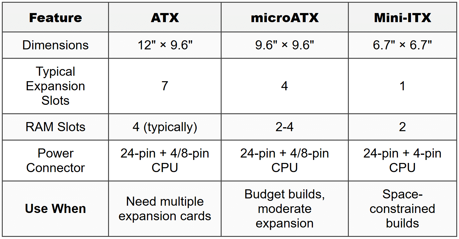
The motherboard is the main circuit board that connects all internal components and determines what hardware you can install. Form factor defines the physical size, mounting hole positions, power connector types, and expansion slot layout.
- ATX (Advanced Technology Extended): 12 inches × 9.6 inches, most common desktop form factor, uses 24-pin main power connector plus 4/8-pin CPU power
- microATX (mATX): 9.6 inches × 9.6 inches, smaller than ATX, fewer expansion slots (typically 4 instead of 7), fits in ATX cases
- Mini-ITX: 6.7 inches × 6.7 inches, compact builds, limited to 1 PCIe slot, passive cooling possible, requires mini-ITX or larger case
- ITX variants: ITX standard defines maximum dimensions-boards can be smaller but must maintain mounting hole compatibility
When to Use This
- Choose ATX when building gaming or workstation systems requiring multiple expansion cards (multiple GPUs, capture cards, sound cards)
- Choose microATX for budget builds or mid-tower cases where space is somewhat limited but you need 2-3 expansion slots
- Choose Mini-ITX for home theater PCs (HTPCs), compact gaming builds, or systems where desk space is critically limited
- Verify case compatibility before purchasing-Mini-ITX board fits in ATX case, but ATX board does not fit in Mini-ITX case
Central Processing Unit (CPU)
The CPU executes instructions and performs calculations. You must match CPU socket type to motherboard, ensure chipset compatibility, and verify BIOS support for specific CPU models.
- Intel sockets: LGA (Land Grid Array)-pins on motherboard, contact pads on CPU. Current: LGA 1700 (12th/13th/14th gen), LGA 1200 (10th/11th gen), LGA 1151 (6th-9th gen)
- AMD sockets: PGA (Pin Grid Array) for older CPUs-pins on CPU, holes in socket. AM4 uses PGA. AM5 switched to LGA
- Socket AM4: Ryzen 1000-5000 series, requires compatible chipset BIOS update for newer CPUs on older boards
- Socket AM5: Ryzen 7000+ series, LGA design, DDR5 only, PCIe 5.0 support
- Thermal paste (thermal compound): Required between CPU and heatsink to transfer heat, apply rice grain-sized amount or use pre-applied paste
- Cooling: Stock coolers included with most CPUs except high-end models, aftermarket required for overclocking or quieter operation
When to Use This
- Verify motherboard socket type matches CPU before purchase-physically incompatible sockets prevent installation
- Check motherboard manufacturer's CPU support list-older boards need BIOS updates to recognize newer CPUs in same socket family
- Replace thermal paste when reseating CPU or if system overheats-dried paste loses thermal conductivity
- Install aftermarket cooler when CPU temperatures exceed 80-90°C under load or noise levels are unacceptable
Random Access Memory (RAM)
RAM provides temporary high-speed storage for data and programs currently in use. System cannot boot without functional RAM, and insufficient capacity causes performance degradation.
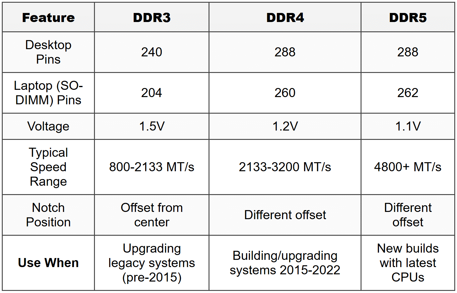
- DDR4: 288 pins (desktop), 260 pins (SO-DIMM laptop), speeds from 2133 MT/s to 3200+ MT/s, voltage 1.2V, notch offset to prevent installing in DDR5 slot
- DDR5: 288 pins (desktop), 262 pins (SO-DIMM), speeds from 4800 MT/s+, voltage 1.1V, on-die ECC, different notch position than DDR4
- DDR3: 240 pins (desktop), 204 pins (SO-DIMM), older standard, 1.5V, still found in legacy systems
- Dual-channel architecture: Install RAM in matching pairs in specific slots (consult motherboard manual-typically slots 2 and 4 first) to double memory bandwidth
- Single-channel vs dual-channel: Dual-channel provides approximately 20-30% better performance in memory-intensive tasks
- Speed matching: Mixing speeds runs all modules at slowest module's speed, mixing capacities works but loses dual-channel if unbalanced
- ECC (Error-Correcting Code): Detects and corrects single-bit errors, requires CPU and motherboard support, used in servers, incompatible with non-ECC boards
When to Use This
- Install RAM in matching pairs in correct slots (usually color-coded or slots 2 and 4) to enable dual-channel mode for maximum performance
- Choose DDR4 for systems built 2015-2022, choose DDR5 for current-generation builds (Intel 12th gen+, AMD Ryzen 7000+)
- Upgrade RAM capacity when system uses 80%+ of available memory during normal workloads-check Task Manager Performance tab
- Use ECC RAM only in servers or workstations where data integrity is critical and motherboard/CPU support ECC
Storage Devices
Storage devices provide permanent data retention. You must know interface types, form factors, and performance characteristics to select appropriate drives and troubleshoot failures.
Hard Disk Drives (HDD)
- 3.5-inch: Desktop drives, 7200 RPM or 5400 RPM, capacities up to 20+ TB, use SATA interface
- 2.5-inch: Laptop drives, 5400 RPM typically, lower capacity than 3.5-inch, SATA interface
- Rotation speed: 7200 RPM faster than 5400 RPM but generates more heat and noise
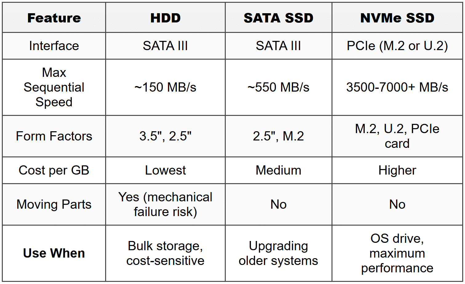
- SATA III (SATA 3.0): 6 Gbps maximum throughput, backward compatible with SATA II devices
Solid State Drives (SSD)
- 2.5-inch SATA SSD: Same form factor as 2.5-inch HDD, SATA III interface (6 Gbps = ~550 MB/s maximum), drop-in replacement for HDD
- M.2 SATA SSD: M.2 form factor, uses SATA protocol, same speed limit as 2.5-inch SATA (~550 MB/s), lengths: 2242, 2260, 2280 (most common), 22110
- M.2 NVMe SSD: Uses PCIe lanes instead of SATA, PCIe 3.0 x4 reaches ~3500 MB/s, PCIe 4.0 x4 reaches ~7000 MB/s, requires M.2 slot with NVMe support (M key or M+B key)
- M.2 keying: B key (SATA or PCIe x2), M key (PCIe x4), B+M key (SATA), notch position prevents incorrect insertion
When to Use This
- Choose 3.5-inch HDD for bulk storage where speed is not critical (media libraries, backups, archives) and cost per GB matters most
- Choose 2.5-inch SATA SSD when upgrading older systems with only SATA ports-provides significant speed improvement over HDD for boot and application loading
- Choose M.2 NVMe SSD for operating system drive in new builds-dramatically faster boot times and application launches than SATA
- Verify motherboard M.2 slot supports NVMe before purchasing NVMe drive-some older M.2 slots are SATA-only
Power Supply Unit (PSU)
The PSU converts AC wall power to DC voltages required by computer components. Insufficient wattage or failing PSU causes system instability, random shutdowns, and boot failures.
- Wattage rating: Calculate total system power draw, add 20% overhead. Typical gaming system needs 650-750W, workstations 850W+
- Voltage rails: +3.3V (RAM, chipset logic), +5V (drives, USB), +12V (CPU, GPU-highest power draw), -12V (legacy), +5VSB (standby power)
- 24-pin main connector: Powers motherboard (20+4 pin design allows compatibility with older 20-pin boards)
- 4+4-pin or 8-pin CPU power: Dedicated 12V power for CPU, high-end systems may require dual 8-pin
- 6-pin and 8-pin PCIe power: GPU power, each 6-pin delivers 75W, each 8-pin delivers 150W, high-end GPUs need 2-3 connectors
- SATA power: 15-pin connector for drives, provides +3.3V, +5V, +12V
- Molex (4-pin peripheral): Legacy connector, +5V and +12V, used for fans and older drives
- 80 PLUS certification: Efficiency rating-Bronze (82%), Silver (85%), Gold (87%), Platinum (90%), Titanium (92%) at 50% load
- Modular vs non-modular: Modular allows disconnecting unused cables for cleaner builds, non-modular has all cables permanently attached
When to Use This
- Calculate system wattage requirements using online PSU calculator or add up component TDP values-never undersize PSU as it causes instability
- Choose modular PSU for cleaner cable management in builds with good airflow requirements or visible side panels
- Select 80 PLUS Gold or higher for systems running 24/7 to reduce electricity costs and heat output
- Replace PSU if system experiences random shutdowns under load, won't power on, or makes clicking/buzzing sounds
Expansion Cards
Expansion cards add functionality via PCIe slots. You must know slot types, lane configurations, and compatibility.
PCIe Slots and Versions
- Physical slots: PCIe x1, x4, x8, x16 (number indicates physical length and maximum lanes)
- Lane configuration: Smaller cards fit in larger slots (x1 card in x16 slot), electrical connection determines actual bandwidth
- PCIe 3.0: ~1 GB/s per lane (x16 = ~16 GB/s)
- PCIe 4.0: ~2 GB/s per lane (x16 = ~32 GB/s)
- PCIe 5.0: ~4 GB/s per lane (x16 = ~64 GB/s)
- Backward compatibility: PCIe 4.0 card works in 3.0 slot at 3.0 speeds, newer cards in older slots operate at slot's maximum version
Graphics Cards (GPU)
- Slot requirement: PCIe x16 slot (most common), may operate electrically at x8 or x16 depending on CPU/chipset lane distribution
- Power connectors: Entry cards use slot power only (75W max), mid-range need 1× 8-pin, high-end need 2-3× 8-pin
- Physical clearance: Check case GPU length clearance, may block adjacent slots with large heatsinks
Sound Cards
- Slot: Typically PCIe x1, provides better audio quality and signal-to-noise ratio than onboard audio
- Use case: Audio production, gaming with high-end headphones, when onboard audio has interference/noise
Network Interface Cards (NIC)
- Wired NIC: PCIe x1, adds Ethernet ports (1 Gbps or 2.5/10 Gbps), used when motherboard NIC fails or additional ports needed
- Wireless NIC: Adds Wi-Fi and Bluetooth, PCIe x1, includes external antennas
When to Use This
- Install dedicated GPU when integrated graphics cannot handle workload (gaming, video editing, 3D rendering, multi-monitor setups)
- Add sound card only when onboard audio produces static/buzzing or lacks required features (optical output, studio-grade DAC)
- Install wired NIC when onboard NIC fails or when upgrading from 1 Gbps to 2.5/10 Gbps for faster local network transfers
- Install wireless NIC when motherboard lacks Wi-Fi or when upgrading to newer Wi-Fi standard (Wi-Fi 6/6E)
Cooling Systems
Inadequate cooling causes thermal throttling (reduced performance) or system shutdowns. Different components require different cooling solutions.
- Case fans: 120mm or 140mm most common, positive pressure (more intake than exhaust) reduces dust, negative pressure improves cooling slightly
- CPU air coolers: Heatsink with fan, adequate for most CPUs, tower coolers (vertical fins) more efficient than low-profile
- All-in-One (AIO) liquid coolers: Closed-loop systems with radiator, pump in CPU block, 240mm/280mm/360mm radiators, better cooling than air for high-end CPUs
- Thermal paste application: Rice grain or small pea-sized amount in CPU center, spreads with heatsink pressure, reapply if removing heatsink
When to Use This
- Use stock CPU cooler for non-overclocked CPUs with 65W TDP or less in typical office/home use
- Install aftermarket air cooler when CPU temperatures exceed 80°C under load or stock cooler is too loud
- Choose AIO liquid cooler for overclocked CPUs, high-TDP processors (105W+), or compact cases where tower cooler blocks RAM slots
- Add case fans when internal case temperature measured near components exceeds 40°C at idle or 70°C under load
Troubleshooting
1. Error: Computer powers on but displays no video, motherboard diagnostic LEDs show CPU error, all fans spin normally.
Resolve: CPU not seated properly or bent pins in socket. Remove CPU cooler, lift retention arm, carefully remove CPU, inspect socket for bent pins (Intel) or CPU pins (AMD older sockets), straighten bent pins with mechanical pencil tip or credit card edge, reseat CPU ensuring orientation marker aligns, secure retention arm, reapply thermal paste, reinstall cooler.
Check first: Inspect CPU socket for bent pins before assuming CPU is defective-bent pins prevent electrical contact and are common installation error.
Do NOT do first: Do not replace motherboard or CPU without inspecting socket-bent pins are repairable and replacing components wastes time and money when simple pin straightening fixes issue.
Why other options are wrong: Reseating RAM or GPU does not resolve CPU error LED indication. PSU provides power if fans spin, so PSU replacement is unnecessary. BIOS update cannot proceed if CPU is not detected.
2. Error: System boots but shuts down after 30 seconds to 2 minutes, CPU temperature shown in BIOS rapidly climbs to 90-100°C.
Resolve: CPU cooler not making proper contact or thermal paste missing/dried. Heatsink may be loose (retention clips not engaged), plastic film not removed from cooler base, or no thermal paste applied. Power off, remove cooler, verify retention mechanism fully engaged, confirm plastic protective film removed from heatsink base, clean old thermal paste with isopropyl alcohol 90%+, apply fresh thermal paste (rice grain amount), reinstall cooler ensuring even pressure.
Check first: Verify CPU cooler retention clips/screws are fully engaged and heatsink is firmly attached with no wiggle-loose heatsink is most common cause of immediate thermal shutdown.
Do NOT do first: Do not assume CPU is defective and replace it-CPUs rarely fail, and thermal issues are almost always mounting or paste problems which are easily correctable.
Why other options are wrong: Insufficient case airflow causes gradual temperature increase over hours, not immediate 90°C+ in under 2 minutes. Overclocking settings would not be present on new build or after BIOS reset. Faulty temperature sensor would show incorrect reading but system would not actually shut down from thermal protection.
3. Error: New RAM installed, system beeps continuously (pattern varies by manufacturer), no display output, sometimes single long beep followed by two short beeps.
Resolve: RAM not fully seated in slot or incompatible RAM installed. Press RAM firmly into slot until retention clips click into locked position on both sides-requires significant force. If still fails, verify RAM is correct DDR generation for motherboard (DDR4 vs DDR5), check motherboard QVL (Qualified Vendor List) for compatibility, test one stick at a time in different slots to isolate bad module or slot.
Check first: Ensure RAM is pressed fully into slot until both retention clips automatically snap into locked position-partially inserted RAM is most common cause of beep codes after RAM installation.
Do NOT do first: Do not immediately assume RAM is defective and return it-improper seating accounts for majority of "new RAM doesn't work" cases and wastes time on returns.
Why other options are wrong: BIOS update not needed for RAM detection unless using extremely new modules on older board. GPU or storage issues produce different error patterns or no beeps at all. PSU would cause no power or random shutdowns, not consistent beep code pattern.
4. Error: Computer powers on for 1-2 seconds, all fans spin, then immediately powers off, cycle repeats continuously with no display output.
Resolve: Power supply failure or short circuit. Most commonly, motherboard standoffs positioned incorrectly causing motherboard to short against case, or modular PSU cable from different manufacturer causing voltage mismatch. First, disconnect all non-essential components (GPU, drives, extra RAM leaving one stick), test boot. If problem persists, verify motherboard standoffs align only with motherboard mounting holes-remove extras. Confirm all PSU cables are from same PSU model. Test with known-good PSU if available.
Check first: Verify motherboard standoffs are positioned only where motherboard has mounting holes and no extra standoffs exist in case that could contact motherboard backside creating short circuit.
Do NOT do first: Do not start replacing expensive components like motherboard or CPU-power cycling indicates electrical protection triggering, usually from short or PSU issue, not failed component.
Why other options are wrong: RAM or CPU issues produce beep codes or solid power-on with no video. Drive failures do not prevent boot attempt. Overheating causes shutdown after some runtime, not instant power-off cycling before POST.
5. Error: M.2 NVMe SSD not detected in BIOS, installed in M.2 slot on motherboard that has two M.2 slots, SATA drives all detected normally.
Resolve: M.2 slot shares PCIe lanes with SATA ports or other M.2 slot. Check motherboard manual for lane sharing configuration-commonly, M.2_2 slot disables SATA ports 5-6 when populated, or using both M.2 slots reduces primary PCIe x16 slot to x8 mode. If NVMe drive installed in M.2 slot designated for SATA-only (some boards have this configuration), drive will not detect. Move NVMe drive to correct M.2 slot that supports NVMe/PCIe mode, or enable M.2 mode in BIOS if option exists, or disconnect SATA devices connected to disabled ports.
Check first: Consult motherboard manual to identify which M.2 slot supports NVMe and what PCIe/SATA port combinations are disabled when M.2 slot is populated-lane sharing is standard design.
Do NOT do first: Do not assume M.2 drive is defective and return it-incorrect slot selection or lane conflict is far more common than failed new drive.
Why other options are wrong: BIOS update rarely needed for standard NVMe drive detection. Driver installation happens in OS, not BIOS detection phase. Secure Boot or UEFI/Legacy settings affect boot mode, not drive hardware detection in BIOS.
Step-by-Step Procedures
Task: Installing RAM
- Power off system, disconnect power cable, press power button to discharge residual power.
- Open case, locate RAM slots near CPU socket, identify correct slots for dual-channel operation (consult motherboard manual-typically slots 2 and 4 for two modules).
- Push down retention clips at both ends of RAM slot to open position (clips fold outward).
- Align RAM module notch with slot key-notch is off-center, only fits one orientation.
- Insert RAM vertically, ensuring gold contacts not visible, press firmly downward on both ends simultaneously until retention clips automatically snap upward into locked position with audible click-requires 20-30 pounds of force.
- Verify both retention clips fully engaged and locked into notches on module sides.
- Reconnect power, boot to BIOS, verify full RAM capacity detected (Check: System Information or Memory section).
- Enter operating system, open Task Manager → Performance → Memory to confirm dual-channel operation if two modules installed.
Task: Installing M.2 NVMe SSD
- Power off system, disconnect power cable, ground yourself with anti-static wrist strap.
- Locate M.2 slot on motherboard, consult manual to identify which slot supports NVMe and what ports it disables.
- Remove M.2 mounting screw and standoff if present at end of slot matching drive length (2280 = 80mm length most common).
- Install standoff at correct position for drive length if not present.
- Insert M.2 drive into slot at 30-degree angle, align notch (M key notch is right side gap), gently push until contacts fully inserted.
- Press drive down flat against standoff, install mounting screw through drive hole into standoff-do not overtighten (finger-tight plus 1/4 turn).
- Boot to BIOS, navigate to Storage or Boot section, confirm drive detected with correct capacity.
- In operating system installation or Disk Management, initialize drive as GPT, create partition, format NTFS or other required filesystem.
Task: Installing Power Supply
- Disconnect all power cables from existing PSU, label connections if reusing components to simplify cable routing.
- Remove PSU mounting screws from rear of case (typically four screws), slide PSU out toward interior.
- Position new PSU in case with fan orientation correct-fan should face ventilation (downward if case has PSU vent on bottom, toward rear if solid bottom).
- Align PSU with mounting holes, install four mounting screws, tighten securely.
- Connect 24-pin main power to motherboard, ensure connector fully seated with locking clip engaged.
- Connect 4+4-pin or 8-pin CPU power to motherboard CPU power socket near CPU (may be labeled EPS12V or CPU_PWR).
- Connect PCIe power cables to GPU if required (6-pin and/or 8-pin), ensure separate cables used for multi-connector GPUs when possible.
- Connect SATA power cables to drives, do not force-connector is keyed with L-shape.
- Route cables for clean airflow, use cable ties or built-in case management, connect PSU power cable to wall outlet, switch PSU power switch to ON (I position).
- Power on system, verify POST, check BIOS hardware monitoring for voltage rails within spec (+12V: 11.4-12.6V, +5V: 4.75-5.25V, +3.3V: 3.14-3.47V).
Practice Questions
Q1: A technician is upgrading a computer's RAM from 16 GB to 32 GB using two new 16 GB DDR4 modules. After installation, the system boots but BIOS shows only 16 GB detected. Both modules are the same brand and speed. What should the technician check first?
(a) Update the motherboard BIOS to latest version
(b) Verify RAM modules are installed in correct slots for dual-channel operation
(c) Reseat the RAM modules ensuring retention clips are fully engaged
(d) Check Windows Task Manager to confirm actual RAM availability
Ans: (c)
Correct answer is reseat RAM ensuring retention clips fully engaged-one module is likely not seated completely, which is most common cause of partial RAM detection. BIOS update (a) is unnecessary for RAM capacity detection. Slot configuration (b) affects dual-channel mode but both modules would still show full capacity even in single-channel. Windows Task Manager (d) is irrelevant when BIOS already shows incorrect capacity indicating hardware detection problem.
Q2: A user reports their computer shuts down randomly during gaming but works fine for office tasks. The shutdowns occur after 15-30 minutes of gaming. BIOS hardware monitor shows CPU temperature at 45°C at idle. What is the most likely cause?
(a) Insufficient power supply wattage for GPU under load
(b) Failing hard drive causing system instability
(c) RAM overheating from insufficient case airflow
(d) Malware consuming system resources
Ans: (a)
Insufficient PSU wattage causes shutdowns specifically during high-load scenarios like gaming when GPU power draw peaks-PSU cannot deliver required power and system shuts down as protection. Failing HDD (b) causes boot failures or application crashes, not clean shutdowns. RAM overheating (c) is extremely rare and would show errors/BSODs, not shutdowns. Malware (d) causes performance degradation but not sudden power-off behavior typical of PSU overload.
Q3: A technician installs a new M.2 NVMe SSD into a motherboard's second M.2 slot (M.2_2). After installation, the NVMe drive is not detected in BIOS, but the existing SATA SSDs work normally. Which troubleshooting step should the technician perform first?
(a) Replace the M.2 NVMe drive with a known-good drive
(b) Check motherboard manual to verify M.2_2 supports NVMe and identify disabled SATA ports
(c) Update motherboard BIOS to add NVMe support
(d) Enable NVMe boot option in BIOS Boot menu
Ans: (b)
Check motherboard manual for M.2_2 slot capabilities and lane sharing configuration-many motherboards have M.2 slots that share lanes with SATA ports or only support SATA mode, not NVMe. This is design limitation, not fault. Replacing drive (a) wastes time when configuration issue is most probable. BIOS update (c) rarely needed for basic NVMe detection on modern boards. Boot option (d) only matters after drive is detected, which has not occurred yet.
Q4: A computer was recently upgraded with a new high-end graphics card. Now the system powers on but displays no video. The GPU fans spin, the motherboard power LED is lit, but there are no beep codes. What should the technician do FIRST?
(a) Reseat the graphics card and verify PCIe power connectors are firmly attached
(b) Replace the power supply with higher wattage model
(c) Clear CMOS to reset BIOS settings
(d) Test with integrated graphics to verify motherboard functionality
Ans: (a)
Reseat GPU and verify PCIe power connections-improper seating or loose power connectors are most common issues with new GPU installation causing no video output despite fans spinning. PSU replacement (b) is premature without confirming current PSU wattage is actually insufficient or testing with reseated card. CMOS clear (c) may help if BIOS settings conflict but physical installation error more likely with new hardware. Testing integrated graphics (d) skips verifying the actual problem component first.
Q5: A system builder is installing a motherboard into a new case. After connecting all cables and powering on, the system runs for 2 seconds then powers off, repeating this cycle continuously. What is the most likely cause?
(a) CPU cooler not properly installed causing immediate thermal protection
(b) Extra motherboard standoff creating short circuit between motherboard and case
(c) RAM incompatibility with motherboard
(d) Graphics card drawing too much power
Ans: (b)
Extra standoff or misaligned standoffs create short circuit between motherboard traces and metal case, triggering immediate power protection shutdown and restart cycle. CPU thermal issue (a) takes longer than 2 seconds to reach thermal limit. RAM incompatibility (c) produces beep codes or powers on without video but does not cause instant power cycle. GPU power draw (d) would cause shutdown under load after successful boot, not immediate cycling before POST.
Q6: A technician needs to select RAM for a new build. The motherboard supports DDR4-3200 and has four RAM slots with dual-channel support. The client needs 32 GB total capacity. Which configuration provides best performance?
(a) Four 8 GB DDR4-3200 modules installed in all four slots
(b) Two 16 GB DDR4-3200 modules installed in slots 2 and 4
(c) Two 16 GB DDR4-2666 modules installed in slots 1 and 2
(d) One 32 GB DDR4-3200 module installed in slot 1
Ans: (b)
Two 16 GB modules in slots 2 and 4 enables dual-channel operation at full rated speed (DDR4-3200) with proper slot population per motherboard design (slots 2 and 4 for two modules is standard). Four modules (a) works but stresses memory controller and may reduce maximum stable speed slightly. Slots 1 and 2 (c) is incorrect slot configuration for dual-channel on most boards, plus slower speed reduces performance. Single module (d) operates in single-channel mode with significantly reduced memory bandwidth.
Quick Review
- ATX: 12" × 9.6", 7 expansion slots. microATX: 9.6" × 9.6", 4 slots. Mini-ITX: 6.7" × 6.7", 1 slot. All use 24-pin + 4/8-pin CPU power.
- DDR4: 288 pins desktop, 260 pins SO-DIMM, 1.2V, up to 3200+ MT/s. DDR5: 288 pins desktop, 262 pins SO-DIMM, 1.1V, 4800+ MT/s. Notch positions different-physically incompatible.
- Dual-channel RAM: Install matching pairs in slots 2 and 4 (typically) for ~20-30% performance increase. Check motherboard manual for correct slot population.
- M.2 NVMe: Uses PCIe lanes, 3500-7000+ MB/s. M.2 SATA: Uses SATA protocol, ~550 MB/s. Check M key (NVMe) vs B+M key (SATA) and motherboard slot support.
- PCIe versions: 3.0 = ~1 GB/s per lane, 4.0 = ~2 GB/s per lane, 5.0 = ~4 GB/s per lane. Backward compatible-newer card in older slot runs at slot speed.
- PSU connectors: 24-pin main, 4+4 or 8-pin CPU, 6-pin PCIe (75W), 8-pin PCIe (150W), 15-pin SATA power. Calculate total wattage + 20% headroom.
- Thermal paste: Rice grain or small pea amount on CPU center. Reapply when removing heatsink. Insufficient paste or missing contact causes immediate thermal shutdown.
- Common boot failures: No video + CPU LED = CPU not seated or bent pins. Beep codes = RAM not fully seated. 2-second power cycle = short circuit (check standoffs) or PSU failure.
- M.2 troubleshooting: Slot may disable SATA ports when populated or only support SATA, not NVMe. Check manual for lane sharing and slot capabilities before assuming drive failure.
- RAM installation force: Requires significant pressure (20-30 lbs) until retention clips automatically snap into locked position with audible click. Partial insertion is most common RAM installation error.


