Networking Hardware


Overview
This chapter covers the physical devices that build and connect networks-routers, switches, access points, firewalls, modems, and cables. You must know what each device does, when to use it, and how to choose between similar devices. Expect questions that test device selection, port counts, speed standards, and basic configuration scenarios.
Core Concepts
Network Interface Card (NIC)
A NIC is the hardware component that connects a device to a network, either wired (Ethernet) or wireless (Wi-Fi). It has a unique MAC address burned into the hardware at manufacture. Modern NICs are usually built into the motherboard, but you can add discrete NICs via PCIe slots or USB adapters.
- Wired NICs: Use RJ45 ports; speeds include 10/100 Mbps (Fast Ethernet), 1 Gbps (Gigabit Ethernet), 10 Gbps, and higher
- Wireless NICs: Use 802.11 standards (a/b/g/n/ac/ax); must match or exceed the access point standard for full speed
- MAC address: 48-bit identifier written as six pairs of hexadecimal digits (e.g., 00:1A:2B:3C:4D:5E)
- Drivers must match the operating system and NIC chipset
When to Use This
- Add a PCIe NIC when the onboard NIC fails or you need higher speeds (e.g., upgrade from 1 Gbps to 10 Gbps)
- Use a USB NIC for temporary connectivity or laptops without Ethernet ports
- Install a wireless NIC to add Wi-Fi to a desktop that only has wired connectivity
Hub
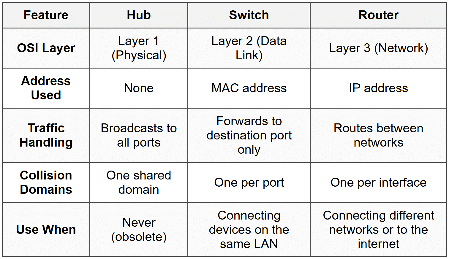
A hub is a legacy device that connects multiple devices on a network by broadcasting all data to every port. It operates at Layer 1 (Physical) of the OSI model and does not examine or filter traffic. All devices share bandwidth, causing collisions and slowdowns as traffic increases.
- No intelligence; no MAC address table
- Half-duplex communication (cannot send and receive simultaneously)
- Creates a single collision domain
- Obsolete; replaced by switches
When to Use This
- You should never use a hub in modern networks-it's inefficient and insecure
- Know it for the exam to distinguish it from switches and to identify it as a wrong answer in performance scenarios
Switch
A switch connects multiple devices on a LAN and uses a MAC address table to forward traffic only to the destination device. It operates at Layer 2 (Data Link) and creates separate collision domains for each port, dramatically improving performance over hubs.
- Learns MAC addresses by examining the source address of incoming frames
- Full-duplex communication on each port (send and receive simultaneously)
- Port counts: 5, 8, 16, 24, 48 ports are common
- Managed switches: Support VLANs, QoS, port mirroring, and remote administration via web interface, CLI, or SNMP
- Unmanaged switches: Plug-and-play; no configuration options; cheaper
- PoE (Power over Ethernet): Delivers power and data over the same Ethernet cable; used for IP cameras, VoIP phones, and wireless access points
- PoE standards: 802.3af (15.4 W), 802.3at (PoE+, 30 W), 802.3bt (PoE++, up to 100 W)
When to Use This
- Use an unmanaged switch for small offices or home networks where you just need to add more wired ports
- Use a managed switch in corporate environments where you need VLANs to segment traffic or QoS to prioritize voice/video
- Use a PoE switch to power devices like IP phones and cameras without running separate power cables
Router
A router connects different networks together and routes traffic between them using IP addresses. It operates at Layer 3 (Network) and makes decisions based on routing tables. Home routers combine a router, switch, wireless access point, and firewall in one device.
- Routes traffic between LANs, WANs, and the internet
- Uses IP addresses and routing tables; does not use MAC addresses for forwarding decisions
- Provides NAT (Network Address Translation) to allow multiple devices on a private network to share one public IP
- DHCP server: Automatically assigns IP addresses to devices on the network
- Default gateway: The router's IP address that local devices use to reach external networks
- Common protocols: RIP, OSPF, BGP for routing decisions
When to Use This
- Use a router to connect your LAN to the internet or to connect multiple LANs together
- Use NAT when you have a limited number of public IP addresses and multiple internal devices
- Configure DHCP on the router to automatically assign IPs instead of manually configuring each device
Wireless Access Point (WAP)
A WAP extends a wired network by creating a wireless network that devices can connect to via Wi-Fi. It operates at Layer 2 and bridges wireless clients to the wired LAN. In a home router, the WAP is built in; in enterprise environments, WAPs are separate devices managed centrally.
- 802.11 standards: 802.11a (5 GHz, 54 Mbps), 802.11b (2.4 GHz, 11 Mbps), 802.11g (2.4 GHz, 54 Mbps), 802.11n (2.4/5 GHz, 600 Mbps), 802.11ac (5 GHz, up to 3.5 Gbps), 802.11ax (Wi-Fi 6, 2.4/5/6 GHz, up to 9.6 Gbps)
- SSID: The network name broadcast by the WAP; can be hidden but this reduces usability, not security
- Channels: 2.4 GHz has 11 channels in North America (only 1, 6, 11 are non-overlapping); 5 GHz has more channels and less interference
- Encryption: WEP (broken), WPA (outdated), WPA2 (minimum acceptable), WPA3 (current best practice)
- Fat AP vs Thin AP: Fat APs operate independently; thin APs require a wireless controller
When to Use This
- Add a WAP to a wired network when you need wireless coverage in areas where running cables is impractical
- Use a PoE-powered WAP to simplify installation (one cable for power and data)
- Deploy thin APs in enterprise environments with many access points for centralized management via a wireless controller
- Use 5 GHz for higher speeds and less interference in dense environments; use 2.4 GHz for better range through walls
Firewall
A firewall filters network traffic based on rules, blocking or allowing packets according to IP addresses, ports, and protocols. It can be hardware (dedicated appliance) or software (running on a computer or router).
- Operates at Layer 3 and Layer 4 (IP and port filtering)
- Stateful firewalls: Track active connections and allow return traffic automatically
- Stateless firewalls: Evaluate each packet independently without tracking connections
- Next-Generation Firewalls (NGFW): Add deep packet inspection, intrusion prevention, and application awareness
- Common ports to remember: HTTP 80, HTTPS 443, FTP 21, SSH 22, Telnet 23, SMTP 25, DNS 53, DHCP 67/68, RDP 3389
When to Use This
- Place a hardware firewall at the network perimeter to protect the entire network from external threats
- Enable the software firewall on individual devices for additional protection, especially on laptops that connect to untrusted networks
- Use stateful inspection to reduce false positives and allow legitimate return traffic without creating separate rules
- Block unused ports and allow only necessary services to minimize attack surface
Modem
A modem converts digital signals from your network into the format required by your ISP's infrastructure (cable, DSL, fiber). It connects your router or computer to the ISP and is often provided by the ISP.
- Cable modem: Uses coaxial cable (DOCSIS standard); speeds up to 1 Gbps or more
- DSL modem: Uses telephone lines; speeds typically 1-100 Mbps depending on distance from the central office
- Fiber modem (ONT): Converts optical signals to electrical; speeds up to 10 Gbps
- Modems operate at Layer 1; they do not route or switch traffic
When to Use This
- Use the modem type that matches your ISP's infrastructure-you cannot substitute a DSL modem for cable service
- For best performance and control, use a separate modem and router instead of an ISP-provided combo unit
- Replace a failing modem when you see frequent disconnections or speeds far below your plan's advertised rate
Patch Panel
A patch panel is a mounted hardware assembly with multiple ports, used to organize and manage network cables in a structured cabling environment. Wall jacks terminate at the back of the patch panel, and short patch cables connect the panel to the switch.
- Common sizes: 12, 24, 48 ports
- Uses 110 punch-down blocks or keystone jacks on the back
- Simplifies troubleshooting and reconfiguration without disturbing wall cabling
- Labeled clearly for each port (room number, desk number, etc.)
When to Use This
- Use a patch panel in any permanent installation where cables run through walls to multiple rooms or desks
- Place the patch panel in a central wiring closet or server room to consolidate all network connections
- Label every port to avoid confusion and reduce troubleshooting time
Power over Ethernet (PoE) Injector
A PoE injector adds power to an Ethernet cable when your switch does not support PoE. It sits between a non-PoE switch and the powered device (like a WAP or IP camera).
- Useful when you have only a few PoE devices and buying a full PoE switch is not cost-effective
- Supports the same PoE standards: 802.3af (15.4 W), 802.3at (30 W), 802.3bt (up to 100 W)
- Requires its own power source (AC adapter or outlet)
When to Use This
- Use an injector when you need to power one or two PoE devices but your existing switch does not support PoE
- Deploy injectors in small offices or temporary setups to avoid replacing the entire switch
- Check the wattage rating to ensure the injector can supply enough power for the device (e.g., a PTZ camera may need 802.3at or higher)
Network Cables and Connectors
Network cables physically connect devices. The most common types are twisted pair (Ethernet), coaxial, and fiber optic. Each has specific use cases, distance limits, and speed capabilities.
Twisted Pair (Ethernet)
- Cat 5: 100 Mbps, 100 meters, obsolete
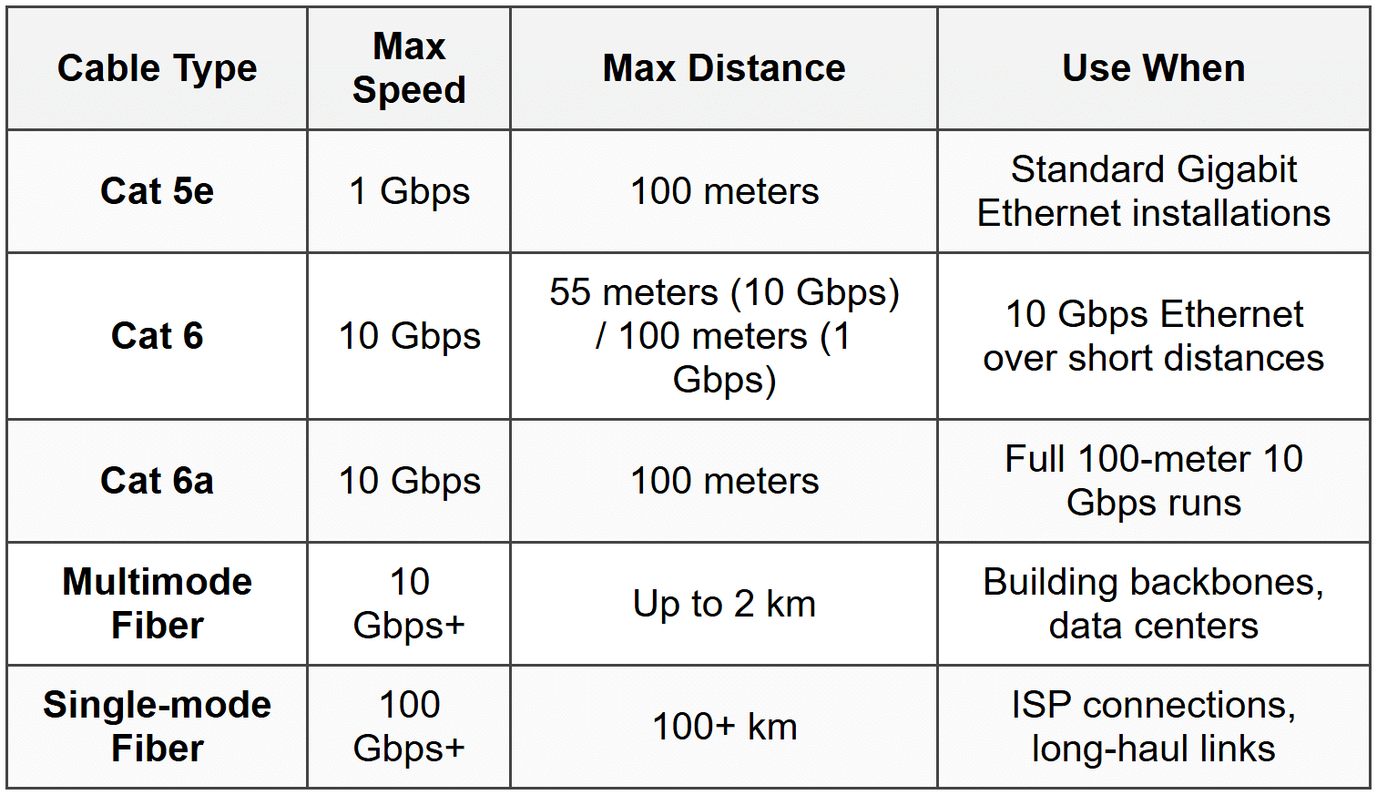
- Cat 5e: 1 Gbps, 100 meters, most common for Gigabit Ethernet
- Cat 6: 10 Gbps up to 55 meters (1 Gbps up to 100 meters), thicker and less flexible than Cat 5e
- Cat 6a: 10 Gbps up to 100 meters, shielded to reduce crosstalk
- RJ45 connector: 8-pin modular connector used for Ethernet cables
- T568A and T568B: Wiring standards; both work but must be consistent on both ends for a straight-through cable
- Straight-through cable: Both ends use the same standard (T568A or T568B); connects devices to switches/routers
- Crossover cable: One end T568A, other end T568B; used to connect similar devices (switch to switch, PC to PC) without Auto-MDIX
- Plenum-rated cable: Fire-resistant jacket for use in air handling spaces (plenum ceilings); required by building codes
When to Use This
- Use Cat 5e for most Gigabit Ethernet installations-cheap and reliable
- Use Cat 6 or Cat 6a when you need 10 Gbps speeds over copper or plan to future-proof the installation
- Use plenum-rated cable in drop ceilings and air ducts to meet fire codes
- Modern switches have Auto-MDIX, so crossover cables are rarely needed; straight-through cables work for everything
Coaxial Cable
- RG-6: Used for cable internet and cable TV; thicker and better shielded than RG-59
- RG-59: Older standard, used for short runs and analog video; not recommended for cable modems
- F-connector: Screw-on connector used on both ends of coaxial cable
- BNC connector: Twist-lock connector used in some legacy video and networking applications
When to Use This
- Use RG-6 for all cable modem and cable TV installations
- Replace RG-59 with RG-6 if you experience signal loss or intermittent connectivity with cable internet
- Tighten F-connectors by hand only; overtightening damages the connector and cable
Fiber Optic Cable
Fiber optic cable uses light to transmit data, providing immunity to electromagnetic interference and supporting very high speeds over long distances.
- Single-mode fiber (SMF): Small core (8-10 microns), uses laser, distances up to 100 km or more, used for long-haul and ISP connections
- Multimode fiber (MMF): Larger core (50 or 62.5 microns), uses LED, distances up to 2 km, used for building backbones and data centers
- LC connector: Small form-factor, push-pull design, most common in modern networks
- SC connector: Square push-pull connector, common in older installations
- ST connector: Bayonet twist-lock, legacy connector
- Fiber is immune to EMI, more secure (cannot be tapped easily), but more expensive and fragile
When to Use This
- Use multimode fiber for runs between switches in the same building or campus (under 2 km)
- Use single-mode fiber for ISP connections, metro networks, and any run over 2 km
- Choose fiber when running cables near heavy electrical equipment or motors where EMI would degrade copper signals
- Use fiber for secure environments where physical cable tapping is a concern
Troubleshooting
1. Error: Users report intermittent network connectivity. Some devices work fine while others disconnect randomly. All devices are connected to the same switch.
Resolve: Failing switch or loose/damaged patch cables at the patch panel or switch. Test each port with a known-good cable and device. Replace the switch if multiple ports fail or behave erratically.
Check first: Physical connections-reseat cables at the switch, patch panel, and wall jacks. Test with a cable tester to identify opens, shorts, or miswires.
Do NOT do first: Replace the router or reconfigure DHCP. The router and DHCP are working for some devices, so the issue is downstream at the switch or cable level.
Why other options are wrong: If the router or DHCP were faulty, all devices would be affected equally, not intermittently or selectively.
2. Error: A new PoE IP camera is connected to a PoE switch but does not power on. The switch shows the port as active, and other PoE devices on the switch work correctly.
Resolve: The camera requires more power than the PoE standard supported by the switch port. Check the camera's power requirements (e.g., 802.3at/30 W) and verify the switch supports that standard. If not, use a PoE+ or PoE++ switch or a separate PoE injector.
Check first: The PoE wattage rating of the switch port and the camera's power requirements in the documentation.
Do NOT do first: Replace the camera or cable. The port is active, so the cable and camera are likely fine; the issue is insufficient power.
Why other options are wrong: A faulty cable would prevent the port from showing as active. A faulty camera would be rare if the device is new and the port works with other PoE devices.
3. Error: Network speeds drop significantly when multiple users transfer large files. The network uses a 10-year-old 8-port device that shows a single collision light blinking constantly during high traffic.
Resolve: The device is a hub, not a switch. Replace it with a managed or unmanaged switch to eliminate the shared collision domain and improve performance.
Check first: The device type and whether it has a MAC address table or collision indicator lights. Hubs create one collision domain; switches create one per port.
Do NOT do first: Upgrade the router or add more bandwidth from the ISP. The bottleneck is internal to the LAN, not the WAN connection.
Why other options are wrong: The router and ISP speed are irrelevant if the local LAN is saturated by hub-induced collisions. Replacing cables will not help because the hub architecture is the problem.
4. Error: A fiber optic link between two switches in different buildings works intermittently. When it fails, the link LED on both switches turns off, then comes back on after a few minutes.
Resolve: Dirty or damaged fiber connectors, or a bent fiber cable. Clean the LC or SC connectors with a fiber cleaning kit and inspect the cable for sharp bends (bend radius below minimum spec). Replace the cable if damaged.
Check first: Physical inspection of the fiber connectors and cable. Dust or scratches on the connector endface cause signal loss. Bend radius violations stress the fiber core.
Do NOT do first: Replace the SFP transceivers in the switches. If both switches see the link come back, the transceivers are likely functioning; the problem is the cable or connectors.
Why other options are wrong: Faulty transceivers would typically cause a permanent failure, not intermittent issues that resolve on their own. Power issues would affect the entire switch, not just one fiber link.
5. Error: A wireless access point cannot be reached for management after being installed on the ceiling. The Ethernet cable tests good from the patch panel to the wall jack, and the WAP worked when tested on the bench.
Resolve: Wrong cable type or miswired cable. Verify that the cable run is wired as a straight-through cable (both ends T568A or both T568B), not a crossover. Re-punch the keystone jack or patch panel termination if the wire order is incorrect.
Check first: Wiring standard on both ends of the cable run using a cable tester or visual inspection. A crossover cable will prevent the WAP from connecting to the switch.
Do NOT do first: Replace the WAP or blame a faulty PoE injector. The WAP worked on the bench, so hardware is not the issue. Test the cable first.
Why other options are wrong: A faulty WAP would not work on the bench. A failed PoE injector would be evident during bench testing if the WAP requires PoE. The cable testing good for continuity does not mean it's wired correctly.
Step-by-Step Procedures
Task: Terminate an RJ45 connector on a Cat 5e cable (T568B standard)
- Strip 1.5 inches of the outer jacket from the cable end using a cable stripper; do not nick the inner wires.
- Untwist the pairs and arrange the wires in T568B order: white-orange, orange, white-green, blue, white-blue, green, white-brown, brown.
- Trim the wires to the same length (about 0.5 inches from the jacket) using flush-cut wire cutters.
- Insert the wires into the RJ45 connector, ensuring each wire reaches the end of the connector and the jacket enters the connector body for strain relief.
- Crimp the connector using a crimping tool, applying firm pressure until the crimper releases.
- Test the cable with a cable tester to verify all eight pins are connected and there are no shorts or miswires.
Task: Install and configure a wireless access point
- Connect the WAP to a PoE switch or PoE injector using a Cat 5e or Cat 6 cable.
- Access the WAP's management interface via a web browser using the default IP address (check the documentation or label on the device).
- Log in with the default username and password (change these immediately to secure the device).
- Configure the SSID (network name) to something recognizable but not revealing (e.g., avoid "Company_Name_WAP_Admin").
- Set the security mode to WPA2 or WPA3 and create a strong passphrase (minimum 12 characters, mix of letters, numbers, symbols).
- Select the appropriate channel: use channels 1, 6, or 11 for 2.4 GHz to avoid overlap; let the WAP auto-select for 5 GHz or choose a DFS channel if supported.
- Disable WPS (Wi-Fi Protected Setup) to prevent brute-force attacks.
- Save settings and reboot the WAP if required.
- Test connectivity by connecting a wireless client and verifying internet access and acceptable signal strength.
Practice Questions
Q1. A technician is setting up a conference room with an IP phone, a wireless access point, and a security camera. The room has only one Ethernet drop. The switch in the wiring closet does not support PoE. Which device should the technician install to power all three devices?
(a) A PoE injector for each device
(b) A small PoE switch in the conference room
(c) A power strip and separate AC adapters
(d) A single PoE injector with multiple outputs
Ans: (b)
Installing a small PoE switch in the conference room allows the technician to use the single Ethernet drop for data and then power all three devices from the PoE switch. Option (a) would require three Ethernet drops. Option (c) defeats the purpose of PoE and adds cable clutter. Option (d) does not exist as a standard product; PoE injectors are typically one-to-one devices.
Q2. A network administrator is troubleshooting slow file transfers between two servers in the same rack. The servers are connected to a switch with Cat 6 cables. Speed tests show only 100 Mbps, but both servers have Gigabit NICs. What should the administrator check first?
(a) Replace the Cat 6 cables with Cat 6a
(b) Verify that Auto-MDIX is enabled on the switch
(c) Check the switch port configuration and cable termination
(d) Upgrade the switch to support 10 Gbps
Ans: (c)
The switch ports may be configured for 100 Mbps or the cable could be miswired or damaged, causing the link to negotiate down to Fast Ethernet. Cat 6 supports Gigabit up to 100 meters, so option (a) is unnecessary. Auto-MDIX (option b) affects straight-through vs crossover functionality, not speed. Upgrading to 10 Gbps (option d) is overkill when the current setup should already support 1 Gbps.
Q3. A small office has 12 workstations connected to an 8-port switch. The switch has two open ports. The office manager wants to add four more workstations. What is the most cost-effective solution?
(a) Replace the 8-port switch with a 24-port switch
(b) Add an 8-port unmanaged switch and connect it to one of the open ports on the existing switch
(c) Replace all Cat 5e cables with Cat 6a
(d) Install a router with additional ports
Ans: (b)
Adding an 8-port switch to one of the open ports expands capacity at minimal cost. Switches can be daisy-chained without performance issues in small networks. Option (a) is more expensive and wastes the existing switch. Option (c) does not add ports. Option (d) is incorrect because routers are not used to expand LAN ports-switches are.
Q4. A technician is installing a WAP in a drop ceiling that will serve 20 users. The WAP supports 802.3af PoE. After installation, the WAP powers on but reboots randomly under heavy load. What is the most likely cause?
(a) The Ethernet cable is longer than 100 meters
(b) The WAP requires 802.3at PoE+ and the switch only provides 802.3af
(c) The SSID is broadcasted and causing interference
(d) The wireless channel overlaps with a neighboring network
Ans: (b)
The WAP may require more power than 802.3af provides (15.4 W) when under load (multiple users, high traffic). 802.3at (PoE+) supplies 30 W. The WAP boots initially but resets when power demand exceeds supply. Option (a) would prevent any connectivity. Options (c) and (d) would cause connectivity issues, not power-related reboots.
Q5. Performance-based task: You are installing a network in a small office. You have a cable modem from the ISP, a wireless router, and three desktop computers. Describe the correct order of devices and connections to provide internet access and wireless connectivity.
Ans:
1. Connect the cable modem to the ISP's coaxial cable drop using an F-connector.
2. Connect the modem's Ethernet port to the router's WAN/Internet port using a Cat 5e or Cat 6 cable.
3. Connect the three desktop computers to the router's LAN switch ports using Cat 5e or Cat 6 cables.
4. Configure the router with the ISP's connection settings (usually DHCP, but may require PPPoE or static IP depending on ISP).
5. Configure the wireless settings (SSID, WPA2/WPA3, passphrase) to enable Wi-Fi access for mobile devices.
Q6. A user reports that their desktop computer, connected via Ethernet, cannot reach the internet but can access local network resources like shared drives and printers. Which of the following should the technician check first?
(a) Verify the default gateway setting on the computer
(b) Replace the Ethernet cable
(c) Reboot the switch
(d) Check the DNS server settings
Ans: (a)
The computer can reach local resources, so the NIC, cable, and switch are functioning. The default gateway routes traffic to external networks (the internet). If it's missing or incorrect, the computer cannot reach the internet. Option (b) is wrong because local access proves the cable works. Option (c) would affect all users, not just one. Option (d) would cause name resolution failures but the user could still reach sites by IP if the gateway were configured correctly.
Quick Review
- A switch uses MAC addresses and operates at Layer 2; a router uses IP addresses and operates at Layer 3.
- PoE standards: 802.3af = 15.4 W, 802.3at (PoE+) = 30 W, 802.3bt (PoE++) = up to 100 W.
- Cat 5e: 1 Gbps up to 100 m; Cat 6: 10 Gbps up to 55 m; Cat 6a: 10 Gbps up to 100 m.
- Multimode fiber: Up to 2 km, LED, cheaper; single-mode fiber: 100+ km, laser, more expensive.
- T568A and T568B: Both ends must match for a straight-through cable; mix them for a crossover (rarely needed with Auto-MDIX).
- WPA2 is the minimum acceptable wireless encryption; WPA3 is current best practice.
- Hubs broadcast to all ports and create one collision domain; switches forward to specific ports and create one collision domain per port.
- Plenum-rated cable is required in air-handling spaces to meet fire codes.
- A default gateway is the router's IP address that local devices use to reach external networks.
- 2.4 GHz channels 1, 6, and 11 are the only non-overlapping channels in North America for Wi-Fi.


