PE Exam Exam > PE Exam Notes > Civil Engineering (PE Civil) > Cheatsheet: Concrete Design
Cheatsheet: Concrete Design


1. Material Properties and Mix Design
1.1 Concrete Strength Properties

1.2 Reinforcing Steel Properties

1.3 Concrete Weight and λ Modification Factor

2. Design Principles and Load Factors
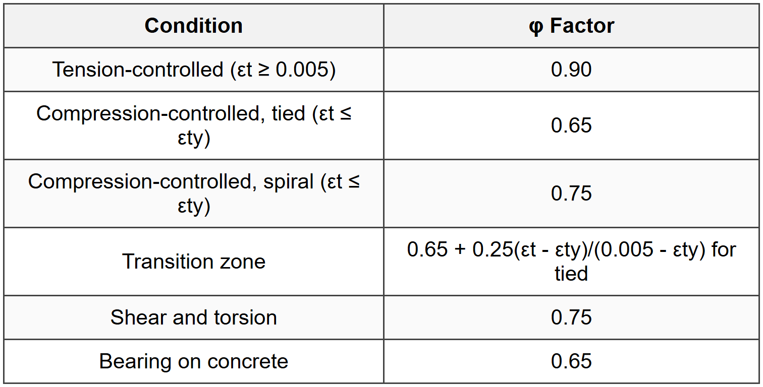
2.1 Strength Reduction Factors (φ)
2.2 Load Combinations (ACI 318)
- U = 1.4D
- U = 1.2D + 1.6L + 0.5(Lr or S or R)
- U = 1.2D + 1.6(Lr or S or R) + (1.0L or 0.5W)
- U = 1.2D + 1.0W + 1.0L + 0.5(Lr or S or R)
- U = 1.2D + 1.0E + 1.0L + 0.2S
- U = 0.9D + 1.0W
- U = 0.9D + 1.0E
3. Flexural Design of Beams
3.1 Rectangular Beam Design Equations

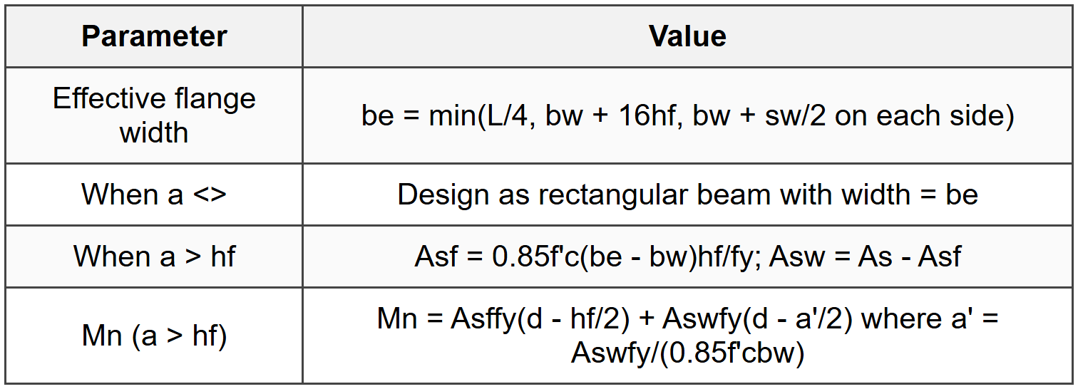
3.2 T-Beam Design
3.3 Doubly Reinforced Beams
- Check if compression steel yields: fs' = 87,000(c - d')/c ≥ fy
- If compression steel yields: Mn = (As - A's)fy(d - a/2) + A'sfy(d - d')
- Where a = (As - A's)fy/(0.85f'cb)
- Net tensile strain must satisfy tension-controlled requirements
4. Shear Design
4.1 Shear Strength Equations

4.2 Stirrup Spacing Requirements

4.3 Critical Sections
- Critical section at distance d from face of support for non-prestressed members
- Vu may be calculated at d from support if: support reaction introduces compression, no concentrated load within d
- For deep beams (ln/h < 4):="" use="" strut-and-tie="">
5. Development Length and Splices
5.1 Development Length for Deformed Bars in Tension

5.2 Development Length in Compression

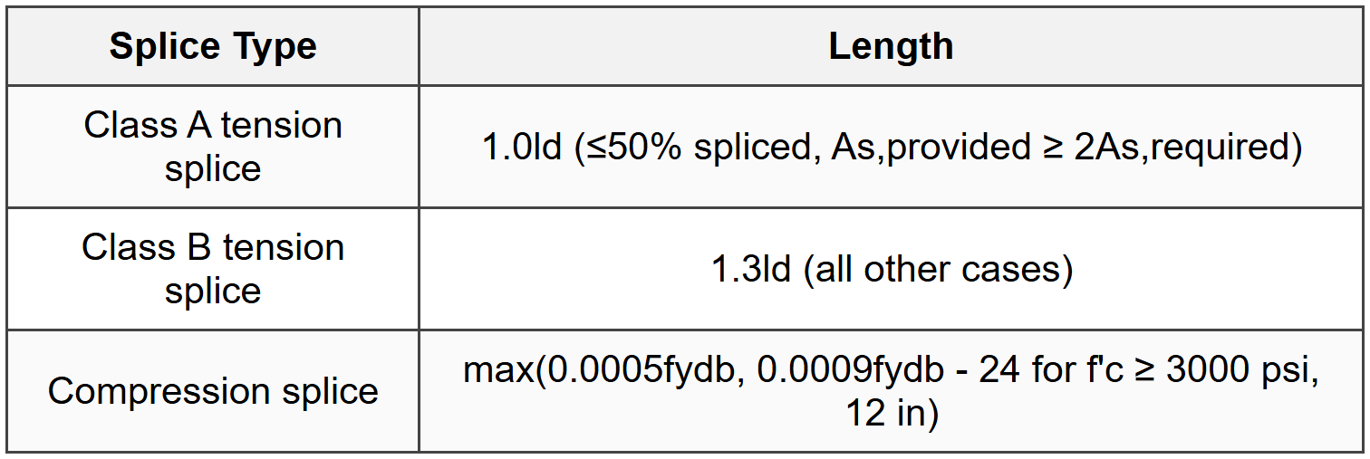
5.3 Splice Lengths
5.4 Standard Hooks (Tension)
- ldh = (0.02fyψe)/(λ√f'c) × db for #11 and smaller
- ψe = 1.0 for uncoated; 1.2 for epoxy-coated
- Modification factors: 0.7 for side/top cover ≥ 2.5 in and #11 hook cover ≥ 2 in; 0.8 for ties/stirrups
- ldh ≥ max(8db, 6 in)
6. Column Design
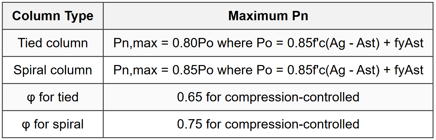
6.1 Column Load Capacity
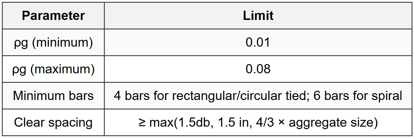
6.2 Reinforcement Limits
6.3 Lateral Reinforcement
6.3.1 Tied Columns
- Minimum tie size: #3 for longitudinal bars #10 and smaller; #4 for #11 and larger
- Vertical spacing: s ≤ min(16db,long, 48db,tie, least column dimension)
- Ties must enclose all longitudinal bars with corner bars enclosed by tie corners
- Every corner and alternate longitudinal bar must have lateral support ≤ 6 in clear
6.3.2 Spiral Columns

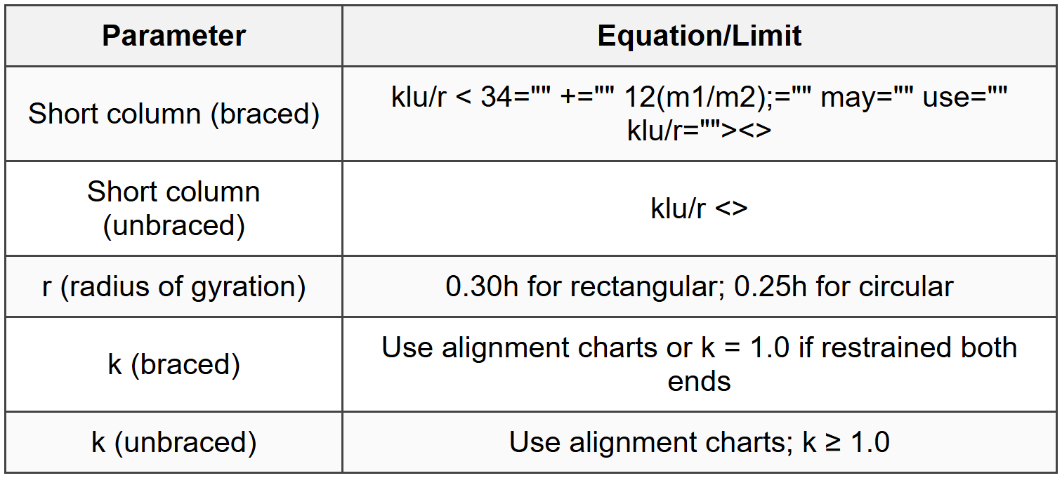
6.4 Slenderness Effects
7. Slab Design
7.1 One-Way Slab Design

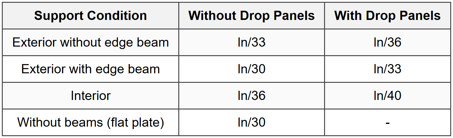
7.2 Two-Way Slab Minimum Thickness
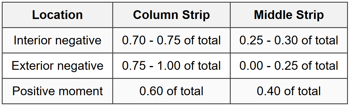
7.3 Two-Way Slab Moment Distribution (Direct Design Method)
7.4 Punching Shear in Slabs

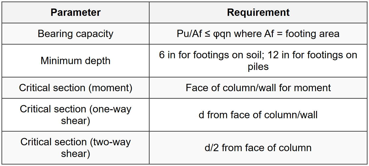
8. Footings
8.1 Spread Footing Design
8.2 Transfer of Force at Base of Column
- Bearing on concrete: φPn = φ0.85f'cA1√(A2/A1) where φ = 0.65
- √(A2/A1) ≤ 2 where A2 is supporting area geometrically similar to A1
- If bearing inadequate, use dowels: As = (Pu - φPn)/φfy
- Minimum dowel area: 0.005Ag of supported column
- Dowel diameter ≤ longitudinal bar diameter + 1/16 in
8.3 Combined Footings
- Resultant of loads should coincide with centroid of footing for uniform bearing
- Design for moment and shear at critical sections
- Check one-way and two-way shear at each column
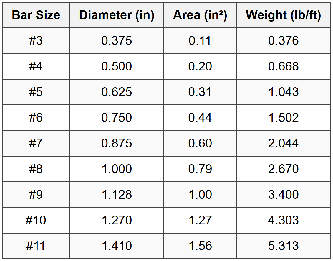
9. Reinforcement Details
9.1 Standard Bar Sizes
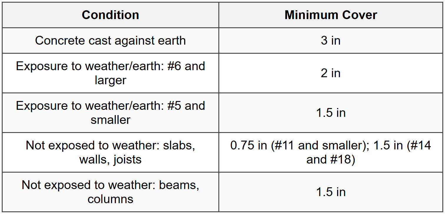
9.2 Concrete Cover Requirements
9.3 Crack Control
- Spacing of reinforcement closest to tension face: s ≤ 15(40,000/fs) - 2.5cc
- Not to exceed s ≤ 12(40,000/fs) where fs = 2fy/3
- For beams with h > 36 in, distribute skin reinforcement along both faces in tension zone
- Ask ≥ 0.012(d - 30)/2 on each face, spacing ≤ min(d/6, 12 in)
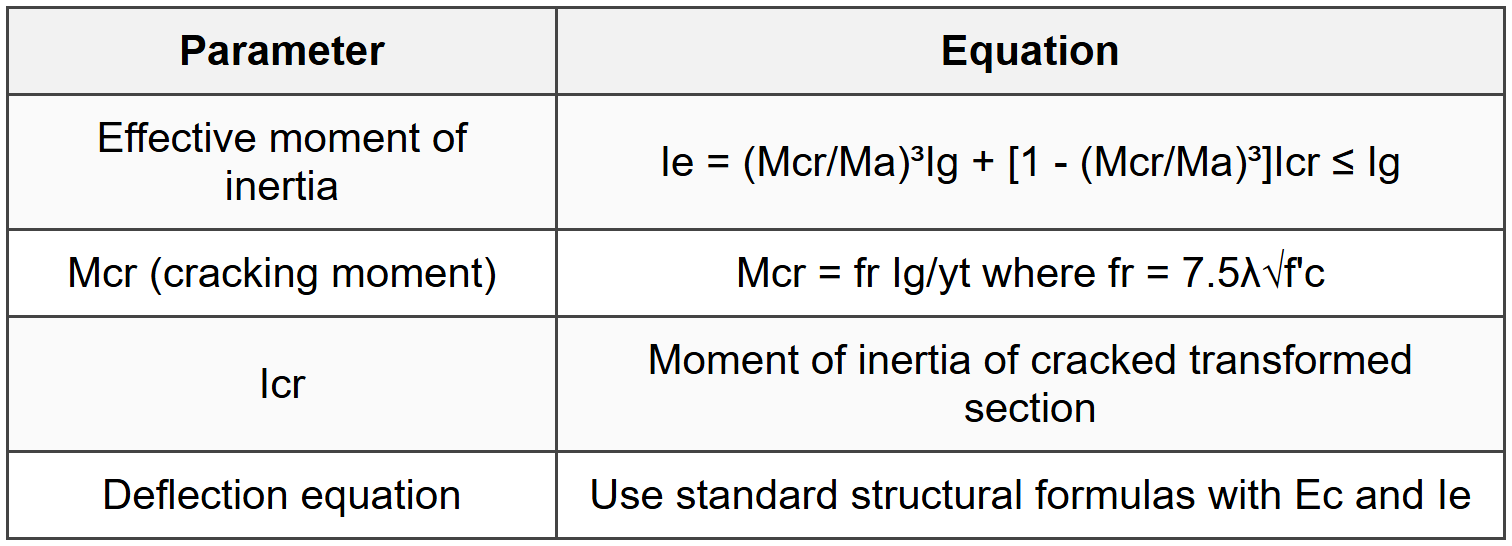
10. Deflection Control
10.1 Immediate Deflection
10.2 Long-Term Deflection
- λΔ = ξ/(1 + 50ρ') where ξ = time-dependent factor
- ξ = 1.0 for 3 months; 1.2 for 6 months; 1.4 for 12 months; 2.0 for 5 years or more
- ρ' = As'/(bd) (compression reinforcement ratio)
- Additional long-term deflection = λΔ × immediate sustained load deflection
10.3 Deflection Limits

11. Special Design Considerations
11.1 Torsion Design

11.2 Brackets and Corbels
- a/d ≤ 1.0 where a = shear span
- Avf (friction steel) ≥ Nuc/(φμfy) where Nuc = factored normal force, μ = 1.4λ for monolithic
- As ≥ (Vua/φfyd) + Nuc(h - d)/(φfyd) + An
- An = Nuc/(φfy) minimum for tension reinforcement
- As,min = max(0.04f'c/fy, As,calculated) × bd
- Closed stirrups Ah ≥ 0.5(As - An)
11.3 Deep Beams
- Deep beam when ln/h ≤ 4 or clear span ≤ 4d
- Use strut-and-tie model for design
- Minimum vertical reinforcement: Av ≥ 0.0025bws
- Minimum horizontal reinforcement: Avh ≥ 0.0025bws2
- Maximum spacing: min(d/5, 12 in)
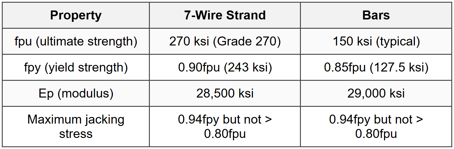
12. Prestressed Concrete
12.1 Prestressing Steel Properties
12.2 Prestress Losses

12.3 Flexural Strength

12.4 Service Load Stresses
- Compression at transfer: ≤ 0.60f'ci
- Tension at transfer (no bonded reinforcement): ≤ 3λ√f'ci (may exceed if shown acceptable)
- Compression at service: ≤ 0.45f'c
- Tension at service (Class U): ≤ 7.5λ√f'c
- Tension at service (Class T): ≤ 6λ√f'c (precompressed zone)
13. Retaining Walls
13.1 Design Requirements

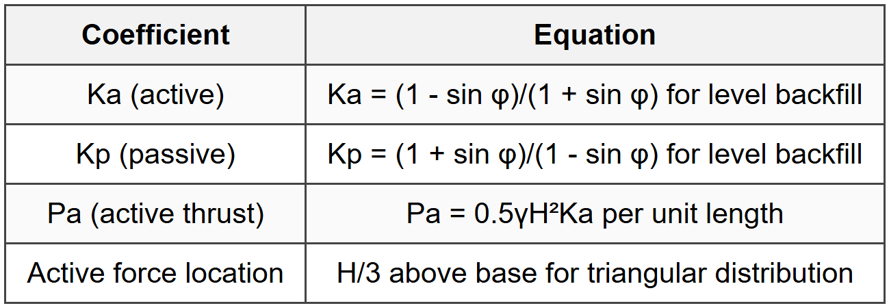
13.2 Lateral Earth Pressure
13.3 Design Considerations
- Check stem for flexure and shear as cantilever from base
- Check heel and toe slabs for flexure and shear
- Increase active pressure by 20% if backfill is sloped or surcharged
- Provide drainage to prevent hydrostatic pressure buildup
- Temperature and shrinkage steel: same as one-way slabs
14. Seismic Design Provisions
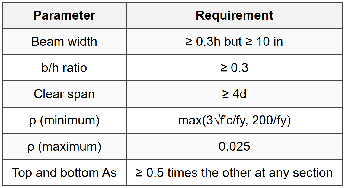
14.1 Special Moment Frame Requirements
14.2 Transverse Reinforcement in Beams
- First hoop at 2 in from column face
- Spacing ≤ min(d/4, 8db, 24db,tie, 12 in) for distance 2h from face
- Hoops required where Vu > φVc/2
- Minimum hoop size: #3 for longitudinal bars ≤ #9; #4 for longitudinal bars > #9
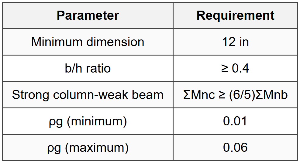
14.3 Special Moment Frame Columns
14.4 Confinement Requirements
- Confine over lo from joint face where lo = max(h, ln/6, 18 in)
- Spacing: min(h/4, 6db, 4 + (14 - hx)/3 in) but ≤ 6 in initially
- Ash = 0.09shcf'c/(fytkbc) or Ash = 0.3(shcf'c/fyt)(Ag/Ach - 1) whichever is greater
- Every corner and alternate longitudinal bar must have seismic hook support
The document Cheatsheet: Concrete Design is a part of the PE Exam Course Civil Engineering (PE Civil).
All you need of PE Exam at this link: PE Exam
About this Document

Apr 20, 2026 Last updated
Related Exams
Document Description: Cheatsheet: Concrete Design for PE Exam 2026 is part of Civil Engineering (PE Civil) preparation. The notes and questions for Cheatsheet: Concrete Design have been prepared according to the PE Exam exam syllabus. Information about Cheatsheet: Concrete Design covers topics like and Cheatsheet: Concrete Design Example, for PE Exam 2026 Exam. Find important definitions, questions, notes, meanings, examples, exercises and tests below for Cheatsheet: Concrete Design.
Introduction of Cheatsheet: Concrete Design in English is available as part of our Civil Engineering (PE Civil) for PE Exam & Cheatsheet: Concrete Design in Hindi for Civil Engineering (PE Civil) course. Download more important topics related with notes, lectures and mock test series for PE Exam Exam by signing up for free. PE Exam: Cheatsheet: Concrete Design
Description
Cheatsheet: Concrete Design of Civil Engineering to help you remember important concepts with short tricks. Start learning for PE Exam exam & improve retention with EduRev.
Information about Cheatsheet: Concrete Design
In this doc you can find the meaning of Cheatsheet: Concrete Design defined & explained in the simplest way possible. Besides explaining types of Cheatsheet: Concrete Design theory, EduRev gives you an ample number of questions to practice Cheatsheet: Concrete Design tests, examples and also practice PE Exam tests
Top Courses for PE Exam
Related Searches
Objective type Questions, Sample Paper, pdf , shortcuts and tricks, Exam, Extra Questions, mock tests for examination, Semester Notes, Previous Year Questions with Solutions, MCQs, ppt, Cheatsheet: Concrete Design, video lectures, Cheatsheet: Concrete Design, Cheatsheet: Concrete Design, Viva Questions, Summary, Free, past year papers, practice quizzes, Important questions, study material;