PE Exam Exam > PE Exam Notes > Electrical & Computer Engineering for PE > Cheatsheet: Protection Systems
Cheatsheet: Protection Systems


1. Protection System Fundamentals
1.1 Basic Definitions

1.2 Protection System Requirements
- Reliability: Must operate when required and avoid false trips
- Selectivity: Isolate only faulted section, minimize outage area
- Speed: Fast operation to minimize equipment damage and maintain stability
- Sensitivity: Detect minimum fault current within zone of protection
- Dependability: Operate for all faults within protected zone
- Security: Avoid operation for faults outside protected zone
1.3 CT and PT Specifications

2. Overcurrent Protection
2.1 Overcurrent Relay Types
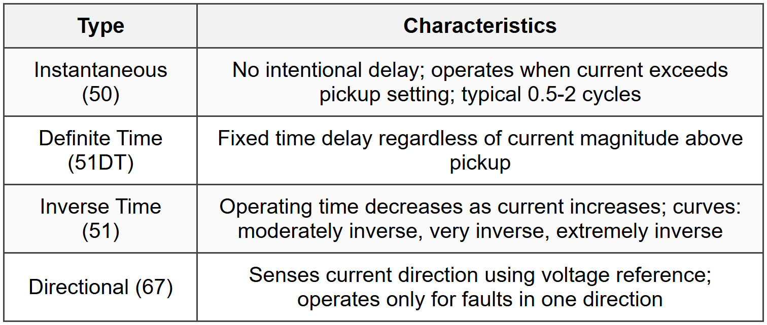
2.2 Inverse Time Characteristics

Where: t = operating time (s), TD = time dial setting, I = fault current, Ip = pickup current
2.3 Coordination Principles
- Coordination Time Interval (CTI): 0.2-0.4s for electromechanical, 0.1-0.3s for electronic relays
- Instantaneous vs Time Overcurrent: Set instantaneous at 150-200% of maximum through fault
- Pickup Setting: 125-150% of maximum load current for phase relays
- Ground Relay Pickup: 10-40% of phase CT rating for solidly grounded systems
- Fuse-Relay Coordination: Minimum 0.2s separation; use fuse minimum melt vs relay curve
3. Distance Protection
3.1 Distance Relay Fundamentals

3.2 Distance Relay Types

3.3 Distance Relay Settings
- Zone 1 Reach: 0.8-0.9 × ZL (line impedance)
- Zone 2 Reach: 1.2 × ZL + 0.5 × ZL2 (shortest adjacent line)
- Zone 3 Reach: 1.2 × (ZL + ZL2)
- Load Impedance Check: Zload_min = Vmin² / (√3 × Pmax); relay reach must be < 0.5="" ×="">
- Power Swing Blocking: Required when Zswing enters relay characteristic; uses rate of impedance change
3.4 Impedance Calculations

4. Differential Protection
4.1 Differential Protection Principles

4.2 Transformer Differential (87T)

4.3 Generator Differential (87G)
- CT Location: Neutral CT and terminal CT; must have identical ratios
- Minimum Pickup: 0.2-0.5 pu on generator base; lower for large units
- Slope: 10-25% for low resistance grounded; 25-40% for high resistance grounded
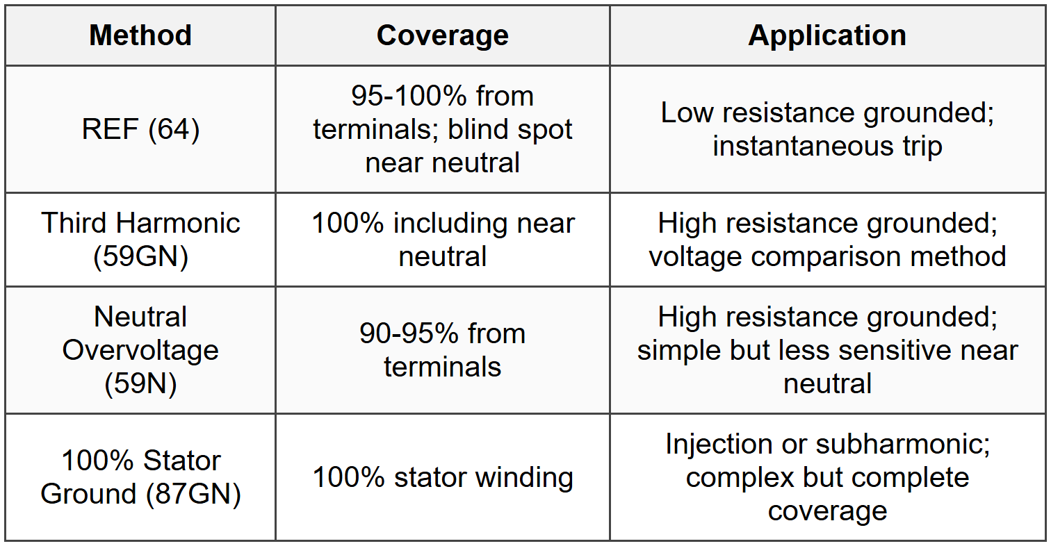
- Stator Ground Fault: Separate 100% stator ground (87GN) using voltage or 3rd harmonic method
- Coordination: Must be faster than backup impedance relay (21); instantaneous operation
4.4 Bus Differential (87B)

4.5 Line Differential (87L)
- Pilot Wire: Uses communication channel; fiber optic or digital communication preferred
- Phase Comparison: Compares phase angle of currents at terminals; trip if out of phase
- Current Differential: Digital comparison of current magnitudes and angles; GPS time sync
- Slope Settings: 15-50% depending on line length and CT errors; dual or triple slope
- Communication Delay: Must account for channel delay (typically <10ms for="">
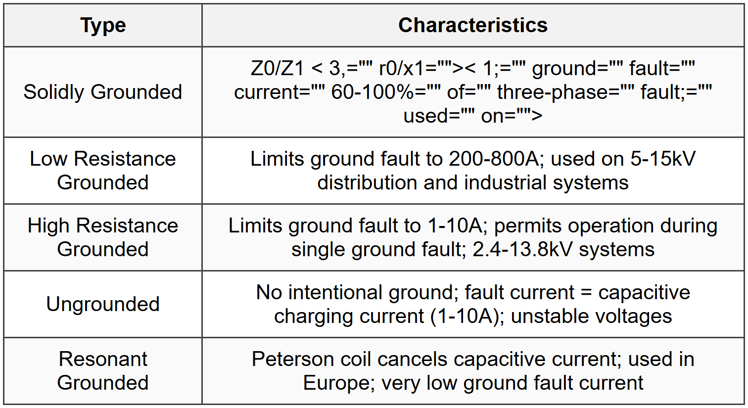
5. Ground Fault Protection
5.1 Grounding System Types
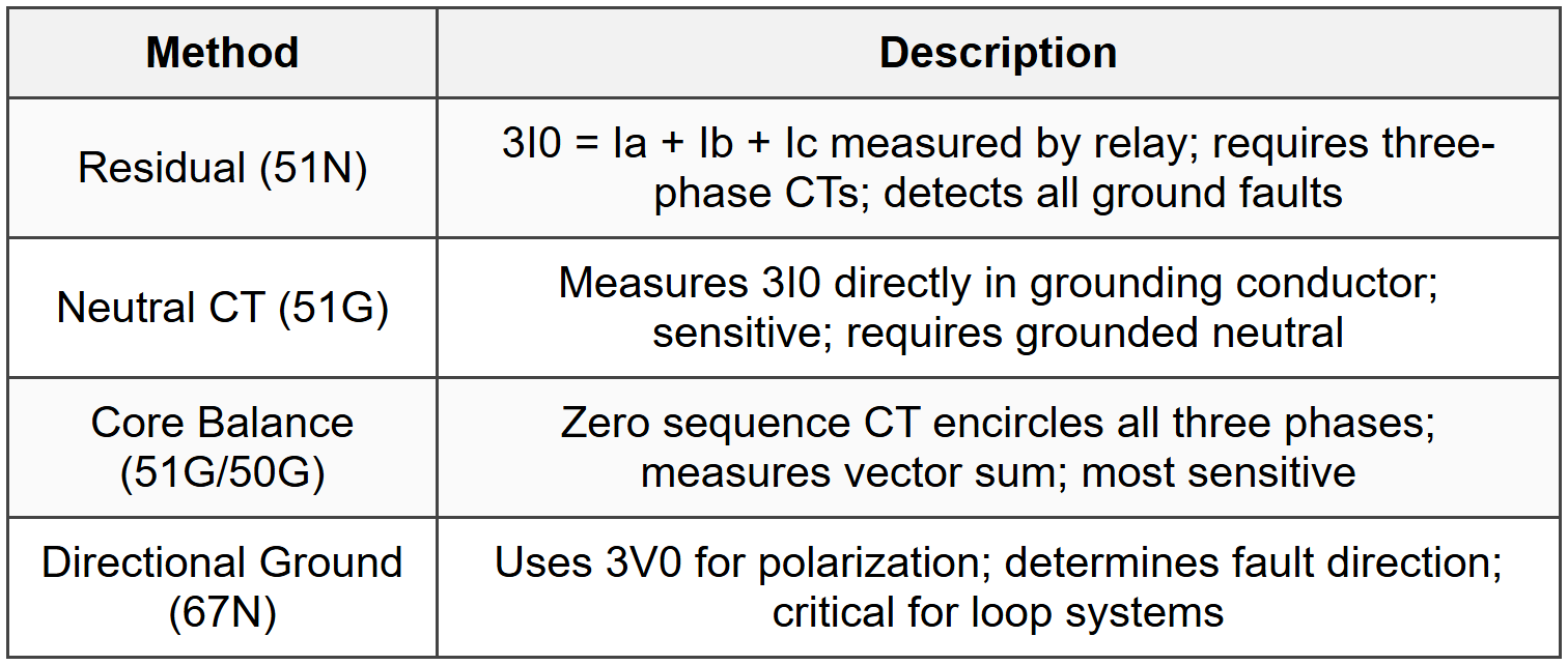
5.2 Residual and Neutral Protection
5.3 Ground Fault Settings
- Solidly Grounded Pickup: 0.1-0.4 × phase CT rating; coordinate with maximum unbalance
- Low Resistance Grounded: 50-70% of resistor current rating; definite time 0.5-1.0s
- High Resistance Grounded: 10-30% of resistor current; pulsing type alerts operator
- SEL Pickup: ≥ 1.5 × maximum unbalance current, ≥ 2 × CT error
- Time Delay: 0.1-0.5s for selectivity; instantaneous if coordination permits
5.4 Restricted Earth Fault (REF/64)

6. Pilot Protection Schemes
6.1 Pilot Scheme Types

6.2 Communication Channels

6.3 Pilot Scheme Settings
- Zone 2 Reach for POTT: 120-150% protected line + 50% adjacent line (minimum)
- Zone 1 Reach: 85-90% of protected line; instantaneous with no communication delay
- Communication Delay: 8-15ms for PLC, 4-8ms for microwave, <5ms for="">
- Carrier Check: Monitors channel; blocks trip if channel fails (security)
- Echo Logic: Confirms received signal matches sent signal; added security
7. Generator Protection
7.1 Generator Protection Functions

7.2 Loss of Field Protection (40)

7.3 Negative Sequence Protection (46)
I2²t Calculation: Thermal limit based on rotor heating
- K Constant: I2²t = K where K = 5-40 for large turbine generators, K = 10-60 for hydro
- Continuous I2 Limit: 5-10% of rated current for turbine generators, 15-25% for hydro
- Alarm Setting: 50-60% of trip setting; warn before trip
- Calculation: I2 = (Ia² + Ib² + Ic² - (Ia+Ib+Ic)²/3)^0.5 / 3
- Time Curve: Inverse time characteristic; t = K/I2² seconds
7.4 Stator Ground Fault Protection
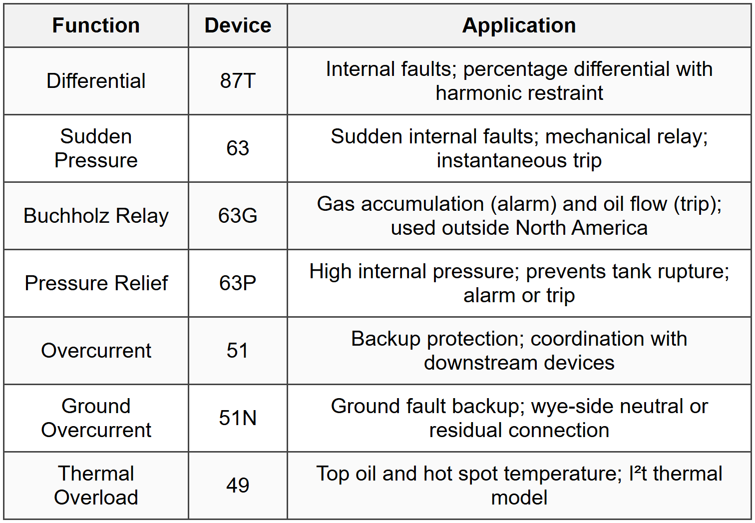
8. Transformer Protection
8.1 Transformer Protection Scheme
8.2 Transformer Differential Settings (87T)
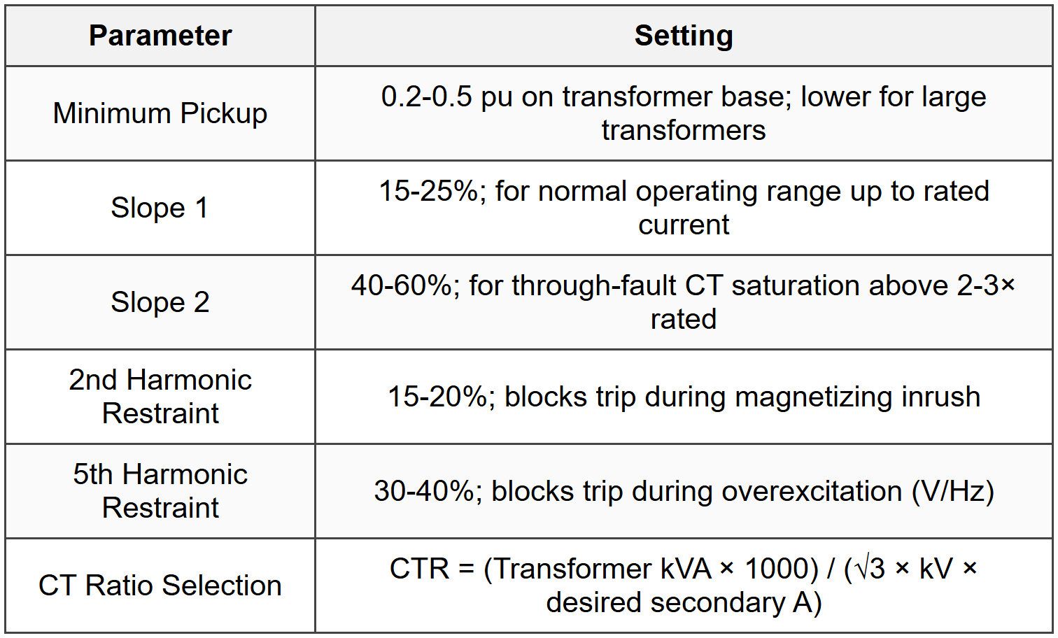
8.3 Inrush Current Characteristics
- Peak Magnitude: 8-15× rated current for large power transformers
- Duration: Decays from seconds to minutes; primarily 2nd harmonic initially
- Harmonic Content: 2nd harmonic 30-70% of fundamental during inrush
- Sympathetic Inrush: Occurs in parallel transformers when one is energized
- Recovery Inrush: After fault clearing; may be 3-5× rated current
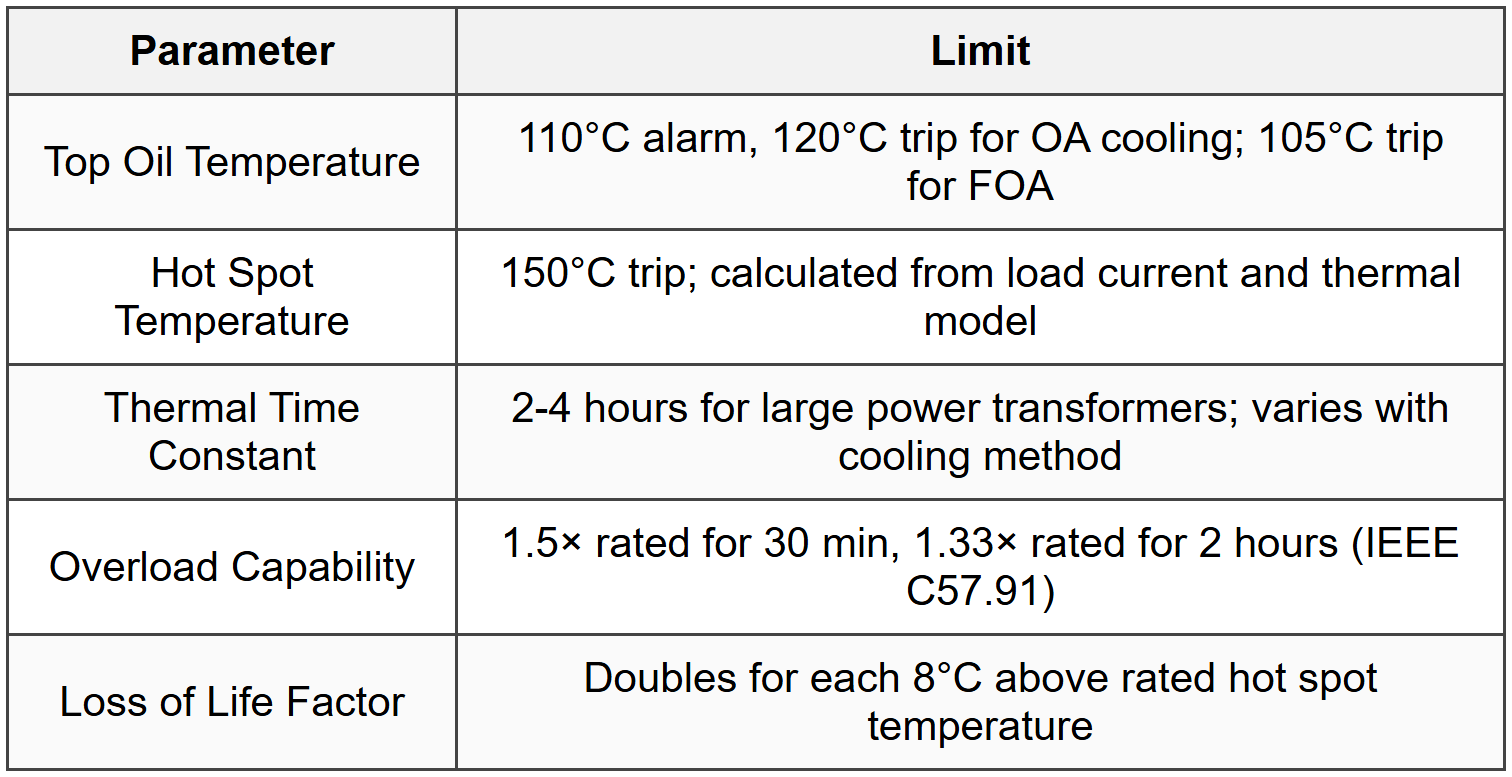
8.4 Thermal Protection (49)
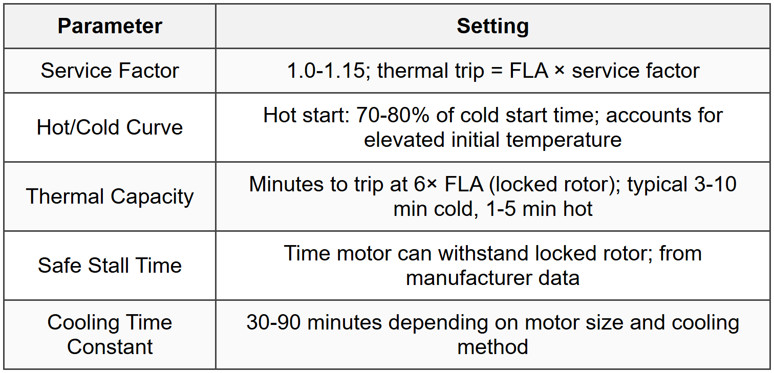
9. Motor Protection
9.1 Motor Protection Functions

9.2 Thermal Overload Settings (49)
9.3 Starting and Locked Rotor Protection
- Starting Current: 5-7× FLA for across-the-line starting; 2-4× for reduced voltage
- Starting Time: 5-15 seconds typical; depends on load inertia
- Locked Rotor Current: 5.5-6.5× FLA at rated voltage (Code G-V)
- 51LR Pickup: 1.5-2.5× FLA; operates if motor fails to accelerate
- 51LR Time Delay: 10-30s; must exceed maximum starting time by 20-30%
- Safe Restarts: 2 starts cold, 1 start hot within 1 hour (general rule)
9.4 Motor Short Circuit Protection

10. Bus Protection
10.1 Bus Protection Schemes

10.2 High Impedance Differential

10.3 Low Impedance Differential
- Operating Current: Iop = |ΣI| (vector sum of all CT currents)
- Restraint Current: Ires = max(|I1|, |I2|, ..., |In|) or (|I1| + |I2| + ... + |In|) / n
- Minimum Pickup: 0.2-0.5A secondary; primary consideration is CT error
- Slope 1: 10-30% for normal through current range
- Slope 2: 50-80% for high through-fault CT saturation region
- Unrestrained Instantaneous: 8-10× maximum load; operates without restraint
- Operating Time: <30ms including="" breaker="" failure="">
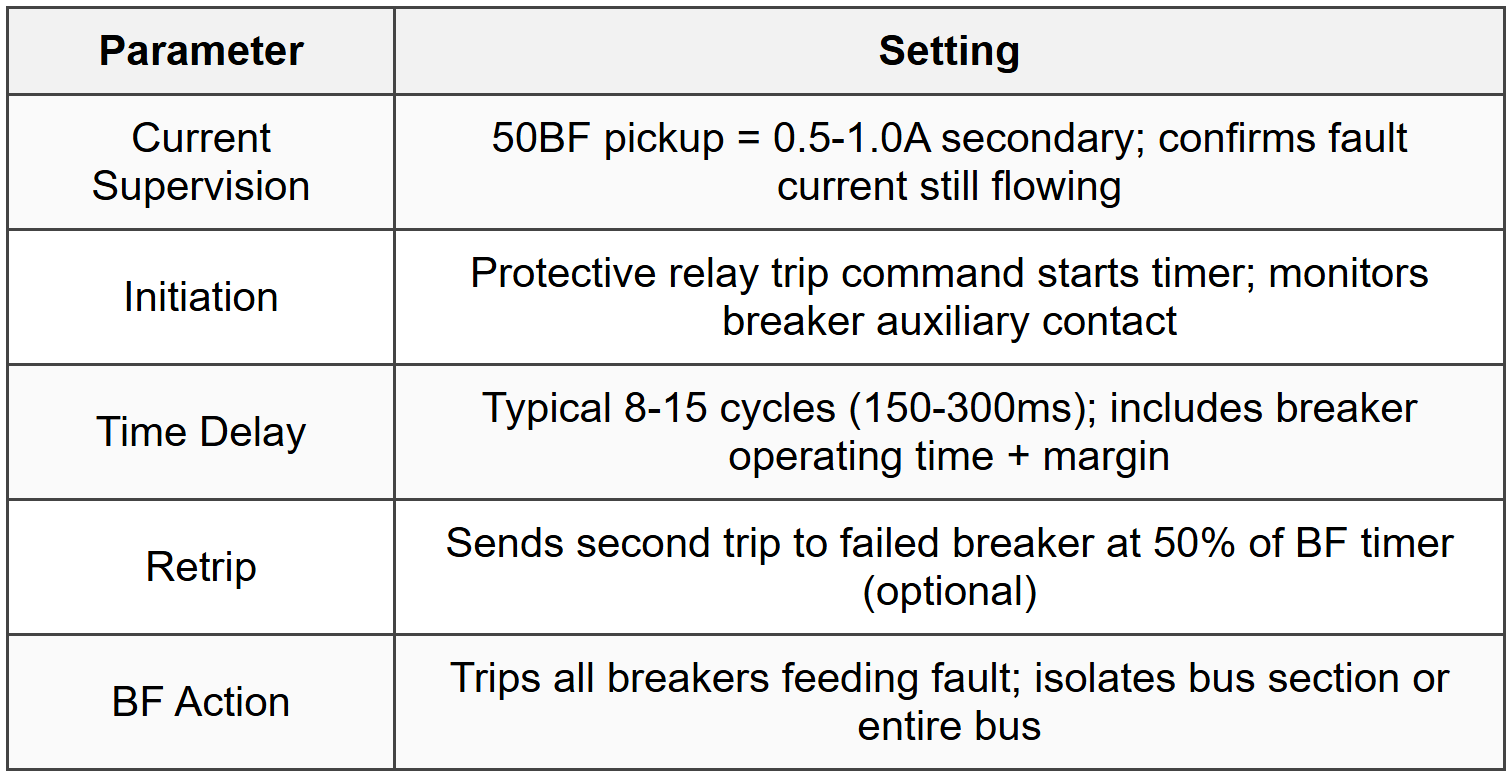
10.4 Breaker Failure Protection (50BF)
11. Special Protection Schemes
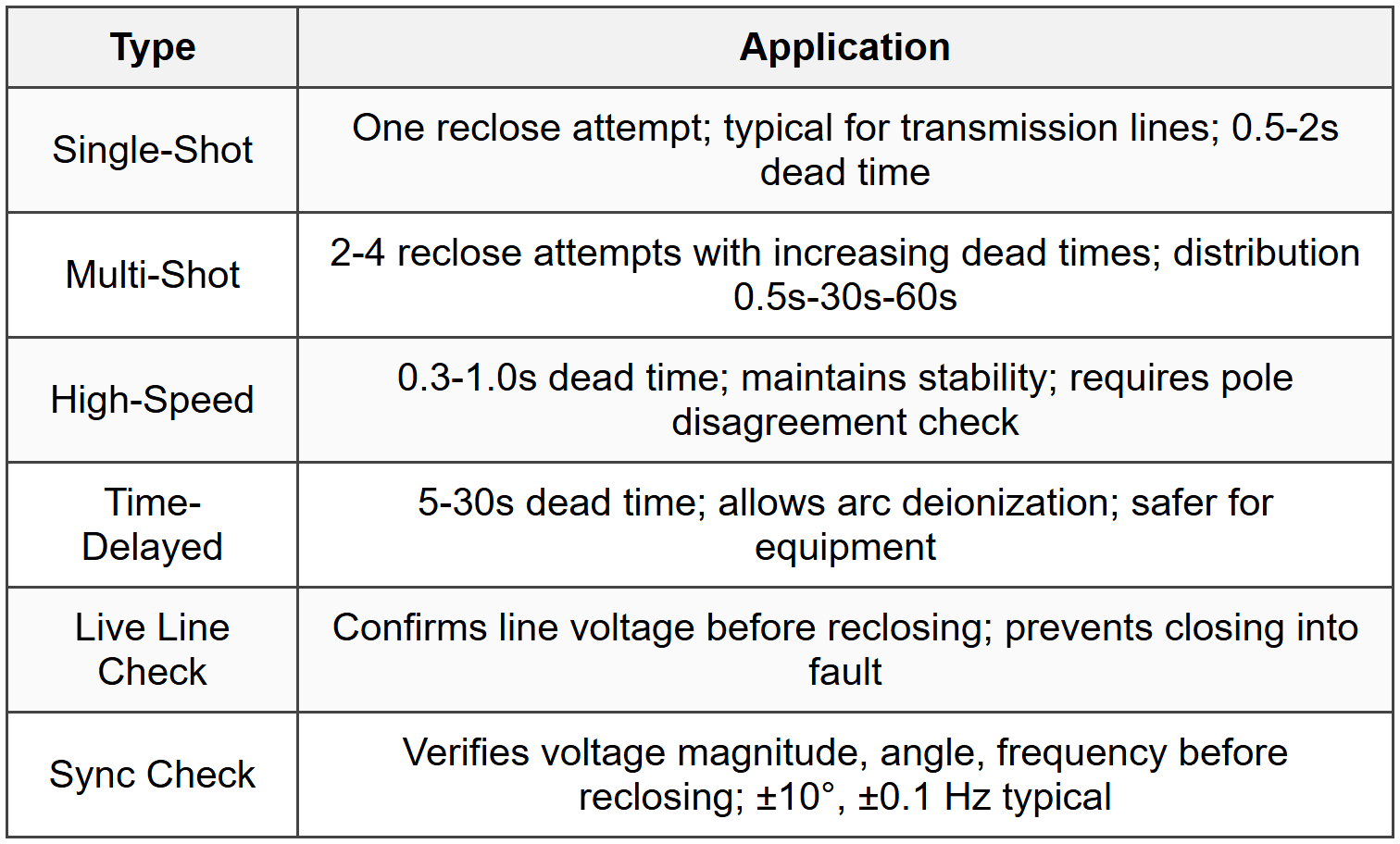
11.1 Reclosing (79)
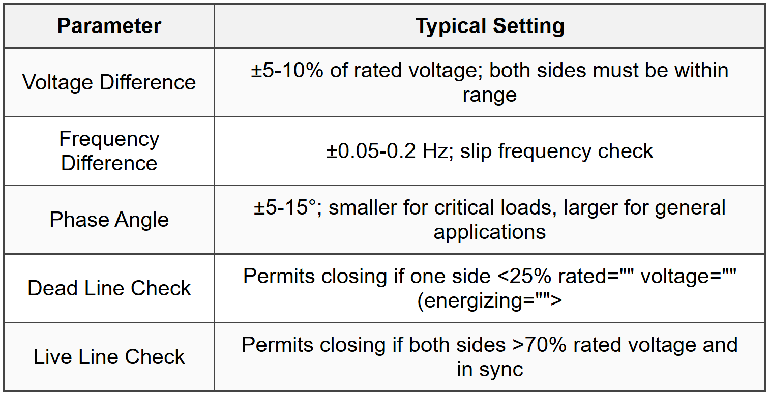
11.2 Sync Check Relay (25)
11.3 Underfrequency Load Shedding (81U)
- Purpose: Restore generation/load balance during frequency decay; prevent system collapse
- Typical Stages: 59.5 Hz (10% load), 59.0 Hz (10%), 58.7 Hz (15%), 58.5 Hz (15%)
- Time Delays: 0.1-1.0s per stage; prevents nuisance tripping for momentary swings
- Rate of Change: df/dt supervision optional; -0.5 to -1.0 Hz/s indicates severe deficit
- Restoration: Manual or automatic after frequency recovers to >59.8 Hz for 5 min
- Load Selection: Non-essential loads first; avoid critical infrastructure
11.4 Overvoltage/Undervoltage Protection

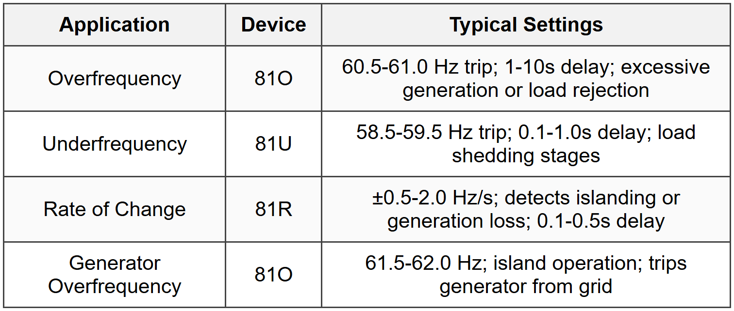
11.5 Frequency Relay Applications
12. Relay Coordination Principles
12.1 Coordination Time Intervals

12.2 Coordination Study Steps
- 1. One-Line Diagram: Complete with all protective devices, ratings, impedances
- 2. Fault Study: Calculate maximum and minimum fault currents at all buses
- 3. Device Selection: Choose relay types, curves, CT/PT ratios
- 4. Starting Point: Begin at load end (furthest downstream device)
- 5. Work Upstream: Each upstream device must coordinate with downstream
- 6. Check Instantaneous: Set at 150-200% of maximum through fault current
- 7. Plot Curves: Verify CTI on time-current curve (TCC) plot
- 8. Sensitivity Check: Verify operation for minimum fault current
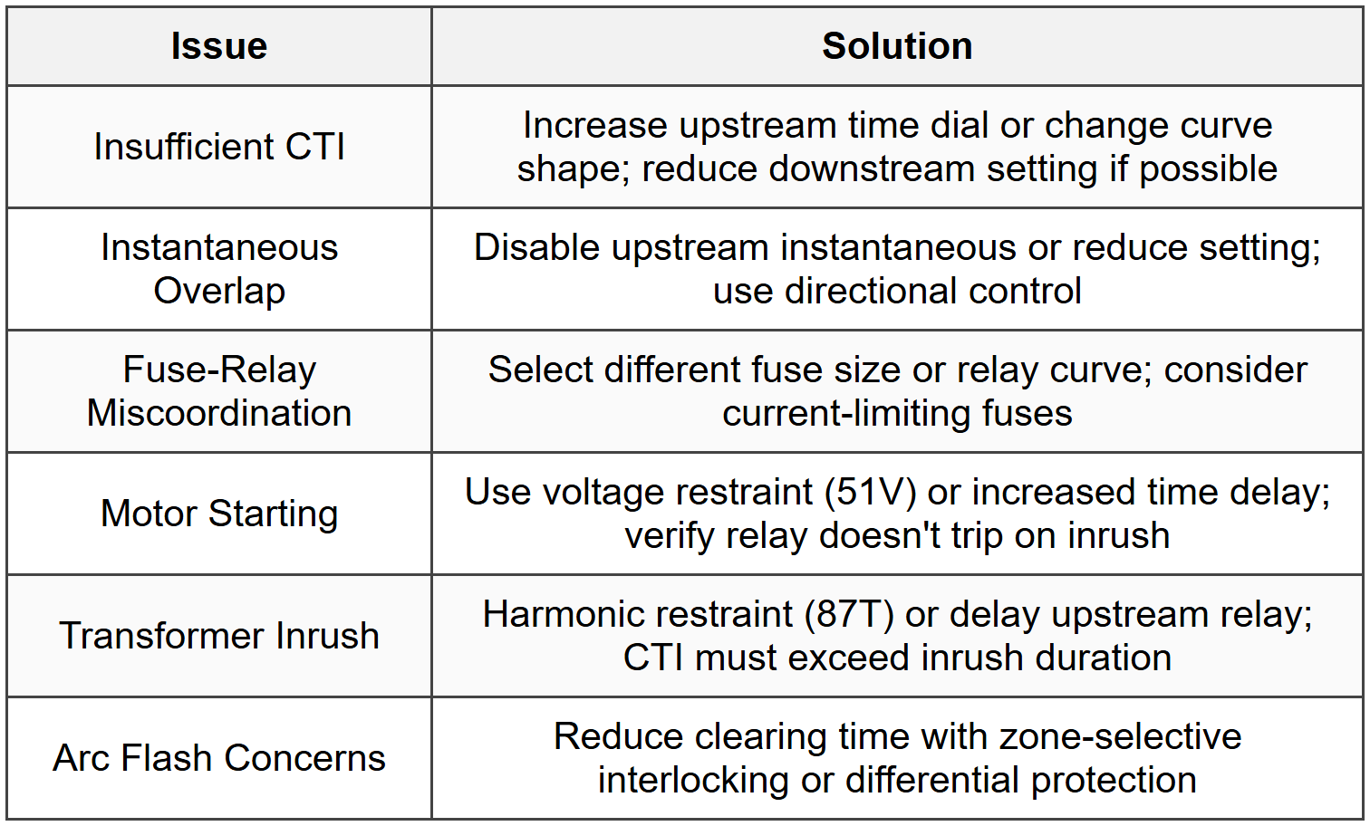
12.3 Common Coordination Issues
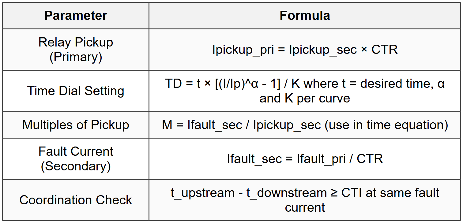
12.4 Relay Setting Calculations
13. ANSI Device Numbers
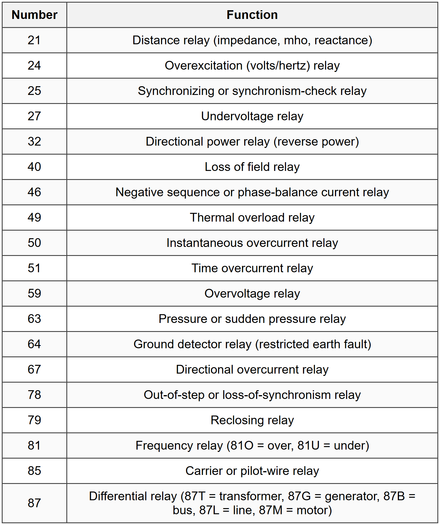
13.1 Common Device Functions
13.2 Suffix Letters

The document Cheatsheet: Protection Systems is a part of the PE Exam Course Electrical & Computer Engineering for PE.
All you need of PE Exam at this link: PE Exam
About this Document

Apr 20, 2026 Last updated
Related Exams
Document Description: Cheatsheet: Protection Systems for PE Exam 2026 is part of Electrical & Computer Engineering for PE preparation. The notes and questions for Cheatsheet: Protection Systems have been prepared according to the PE Exam exam syllabus. Information about Cheatsheet: Protection Systems covers topics like and Cheatsheet: Protection Systems Example, for PE Exam 2026 Exam. Find important definitions, questions, notes, meanings, examples, exercises and tests below for Cheatsheet: Protection Systems.
Introduction of Cheatsheet: Protection Systems in English is available as part of our Electrical & Computer Engineering for PE for PE Exam & Cheatsheet: Protection Systems in Hindi for Electrical & Computer Engineering for PE course. Download more important topics related with notes, lectures and mock test series for PE Exam Exam by signing up for free. PE Exam: Cheatsheet: Protection Systems
Description
Cheatsheet: Protection Systems of Electrical & Computer Engineering to help you remember important concepts with short tricks. Start learning for PE Exam exam & improve retention with EduRev.
Information about Cheatsheet: Protection Systems
In this doc you can find the meaning of Cheatsheet: Protection Systems defined & explained in the simplest way possible. Besides explaining types of Cheatsheet: Protection Systems theory, EduRev gives you an ample number of questions to practice Cheatsheet: Protection Systems tests, examples and also practice PE Exam tests
Top Courses for PE Exam
Related Searches
Important questions, Free, MCQs, shortcuts and tricks, Objective type Questions, study material, pdf , past year papers, mock tests for examination, Summary, Viva Questions, video lectures, practice quizzes, Cheatsheet: Protection Systems, Cheatsheet: Protection Systems, Sample Paper, Semester Notes, Extra Questions, Cheatsheet: Protection Systems, ppt, Exam, Previous Year Questions with Solutions;