PE Exam Exam > PE Exam Notes > Chemical Engineering for PE > Cheatsheet: Hazard Analysis
Cheatsheet: Hazard Analysis


1. Hazard Identification Methods
1.1 What-If Analysis

1.2 Checklist Analysis

1.3 What-If/Checklist Combination
- Combines creative brainstorming with systematic checklist verification
- Uses checklist to ensure coverage while allowing creative questions
- Suitable for moderately complex processes
1.4 Hazard and Operability Study (HAZOP)

1.4.1 HAZOP Guide Words and Parameters

1.4.2 Common Process Parameters
- Flow, Pressure, Temperature, Level, Composition, pH, Viscosity, Phase, Time, Sequence
1.5 Failure Modes and Effects Analysis (FMEA)
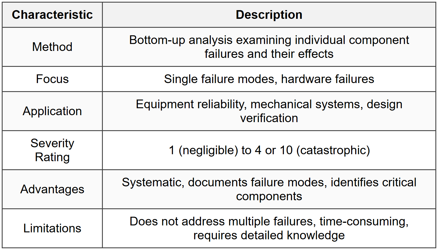
1.5.1 Failure Mode Categories
- Fails to operate (no output)
- Inadvertent operation (unintended output)
- Premature operation (early activation)
- Fails to shut off (continues when should stop)
- Degraded operation (reduced performance)
1.6 Fault Tree Analysis (FTA)

1.6.1 Fault Tree Logic Gates
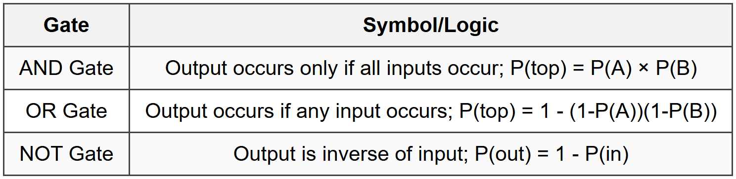
1.6.2 Fault Tree Quantification
- Independent events: Calculate using probability formulas for AND/OR gates
- For rare events (P < 0.1):="" or="" gate="" ≈="" sum="" of="" individual="">
- Minimal cut sets identify critical failure combinations
1.7 Event Tree Analysis (ETA)

1.8 Layer of Protection Analysis (LOPA)
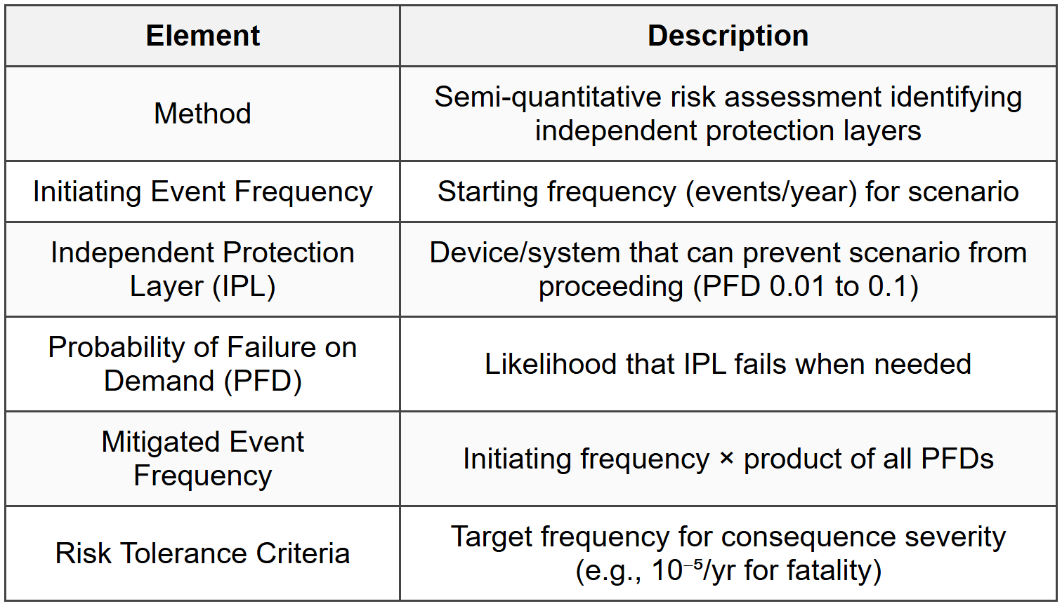
1.8.1 Independent Protection Layer Examples and PFD Values

1.8.2 LOPA Calculation
- Mitigated Frequency = Initiating Event Frequency × PFD₁ × PFD₂ × ... × PFDₙ
- Compare mitigated frequency to risk tolerance criteria
- If mitigated frequency > criteria, add additional IPLs
2. Risk Assessment and Consequence Analysis
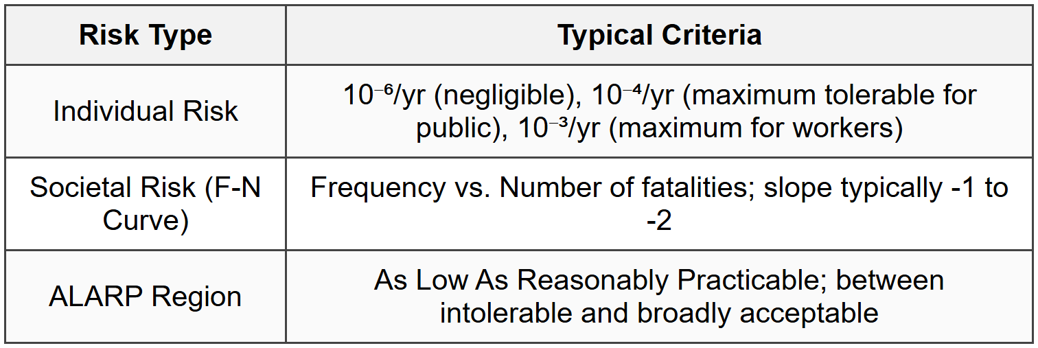
2.1 Risk Definitions

2.2 Risk Matrix

2.3 Individual and Societal Risk Criteria
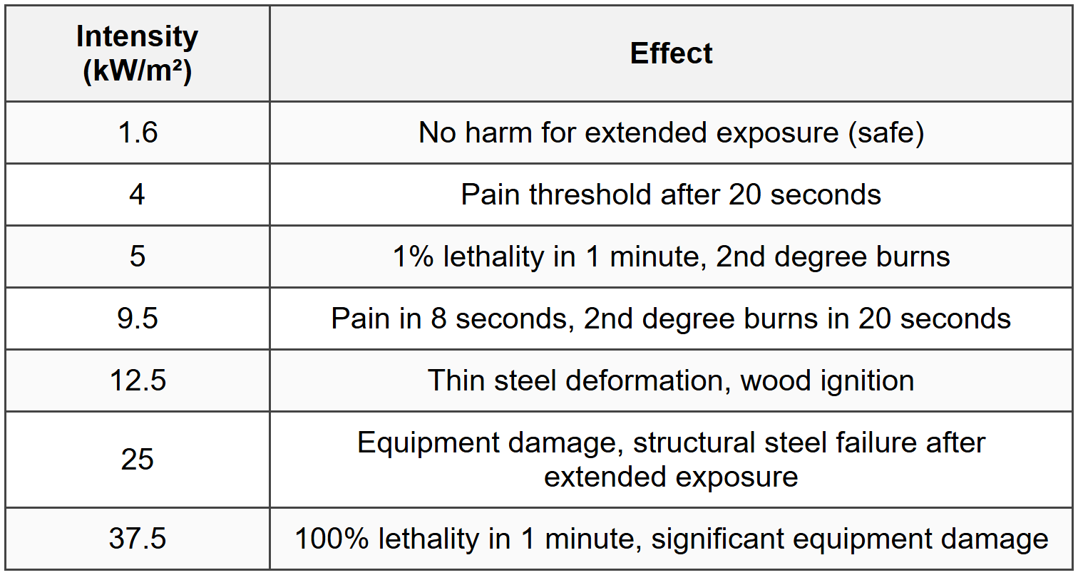
2.4 Thermal Radiation Effects
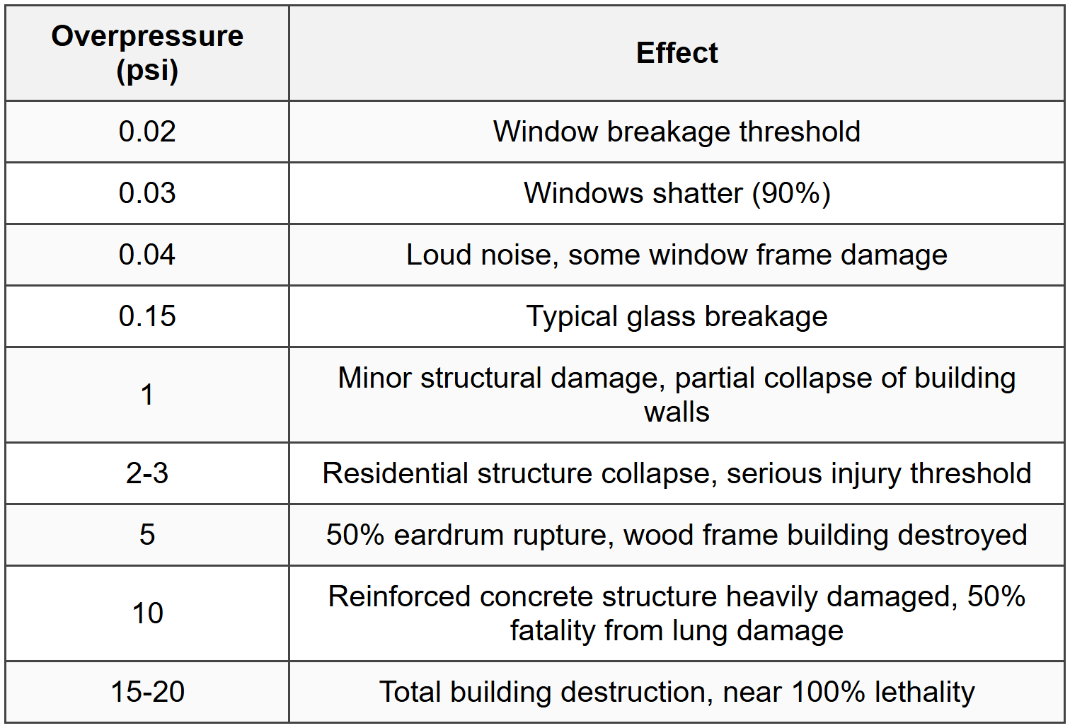
2.5 Overpressure Effects
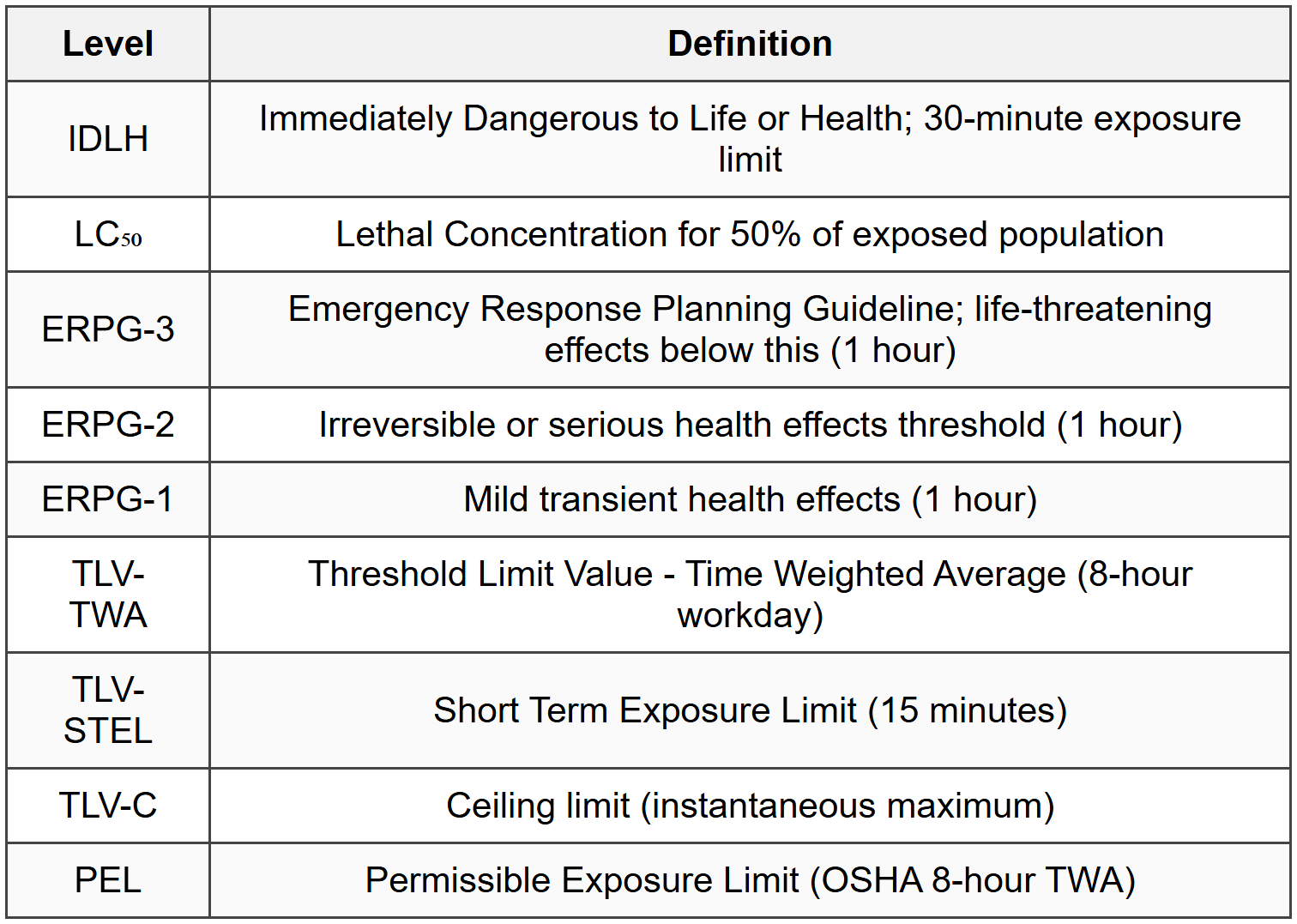
2.6 Toxic Exposure Criteria
2.7 Probit Equations
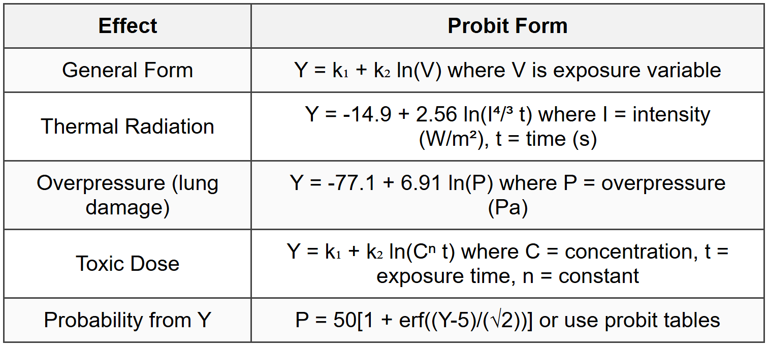
2.8 Dose-Response Relationships
- Toxic Load: TL = Cⁿ × t (concentration to power n times exposure time)
- For many gases: n = 1 (Haber's rule), n = 2 (Ten Berge for irritants)
- Probit Y = 5 corresponds to 50% response (LC₅₀ or LD₅₀)
- Probit Y = 2.67 corresponds to 1% response
- Probit Y = 7.33 corresponds to 99% response
3. Safety Instrumented Systems and Functional Safety
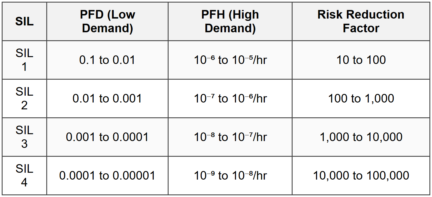
3.1 Safety Integrity Level (SIL)
3.2 Safety Instrumented Function (SIF) Components

3.3 SIF Architecture and Redundancy

3.3.1 PFD Calculations for Architectures
- 1oo1: PFD = λ × T / 2 (where λ = failure rate, T = test interval)
- 1oo2: PFD ≈ (λ × T)² / 3 (both must fail)
- 2oo2: PFD ≈ λ × T (either failing causes system failure)
- 2oo3: PFD ≈ (λ × T)² (two of three must fail)
- For diverse components: use individual failure rates
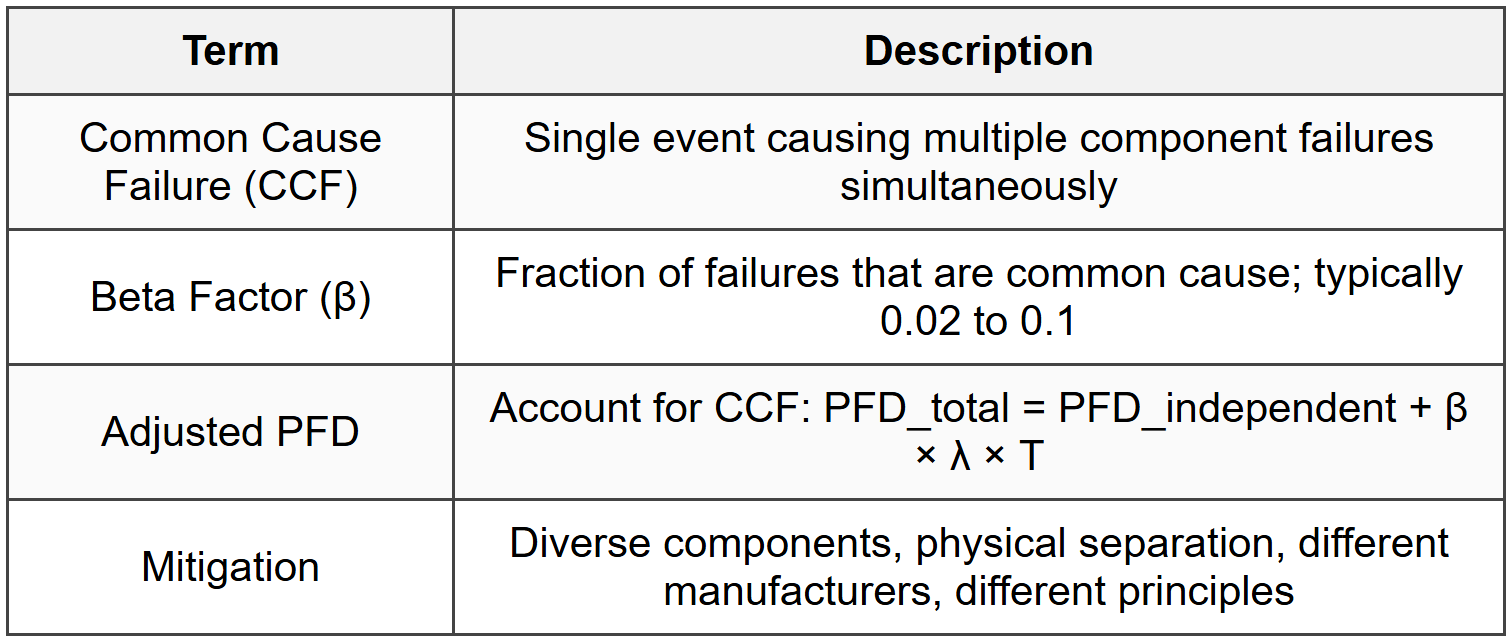
3.4 Common Cause Failure
3.5 Proof Test and Testing Intervals

3.6 Safe Failure Fraction (SFF)

3.7 Spurious Trip Rate (STR)
- Frequency of false trips causing unnecessary process shutdowns
- STR = λ_spurious (spurious trip rate per hour)
- Target: < 1="" spurious="" trip="" per="" year="" for="" critical="">
- Trade-off with PFD: redundant voting (2oo3) reduces spurious trips but increases PFD slightly
3.8 IEC 61511 Safety Lifecycle

4. Inherently Safer Design
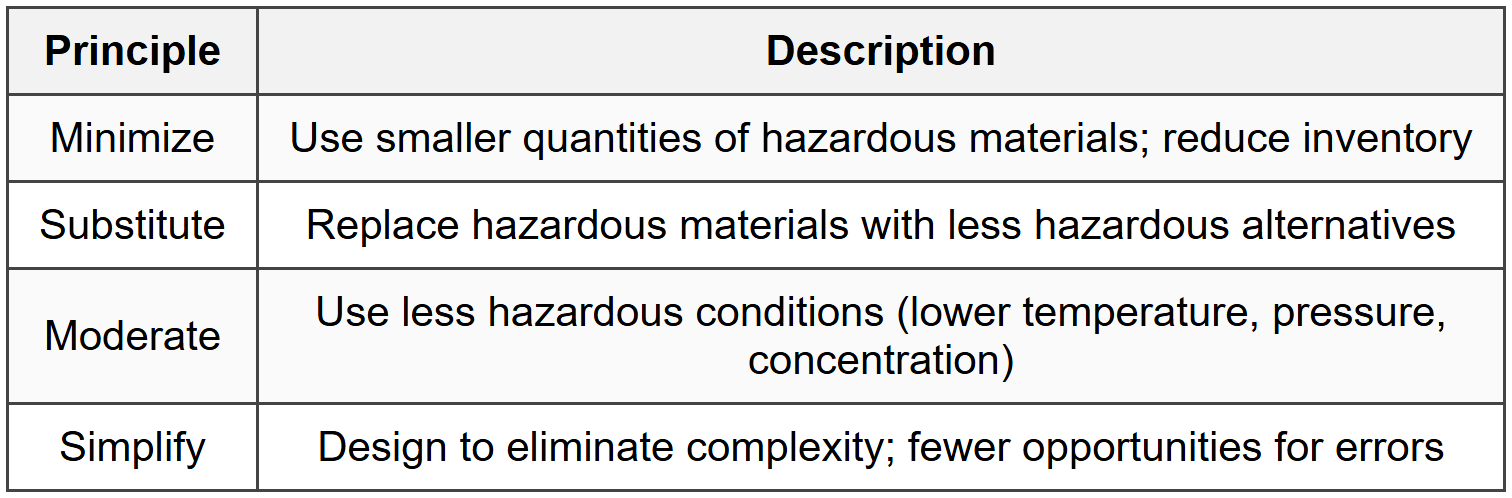
4.1 Inherently Safer Design Principles
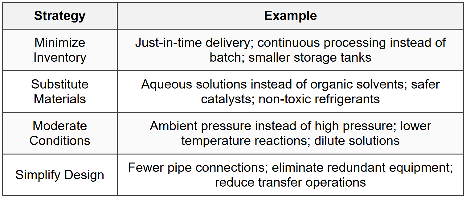
4.2 Examples of Inherently Safer Design Strategies
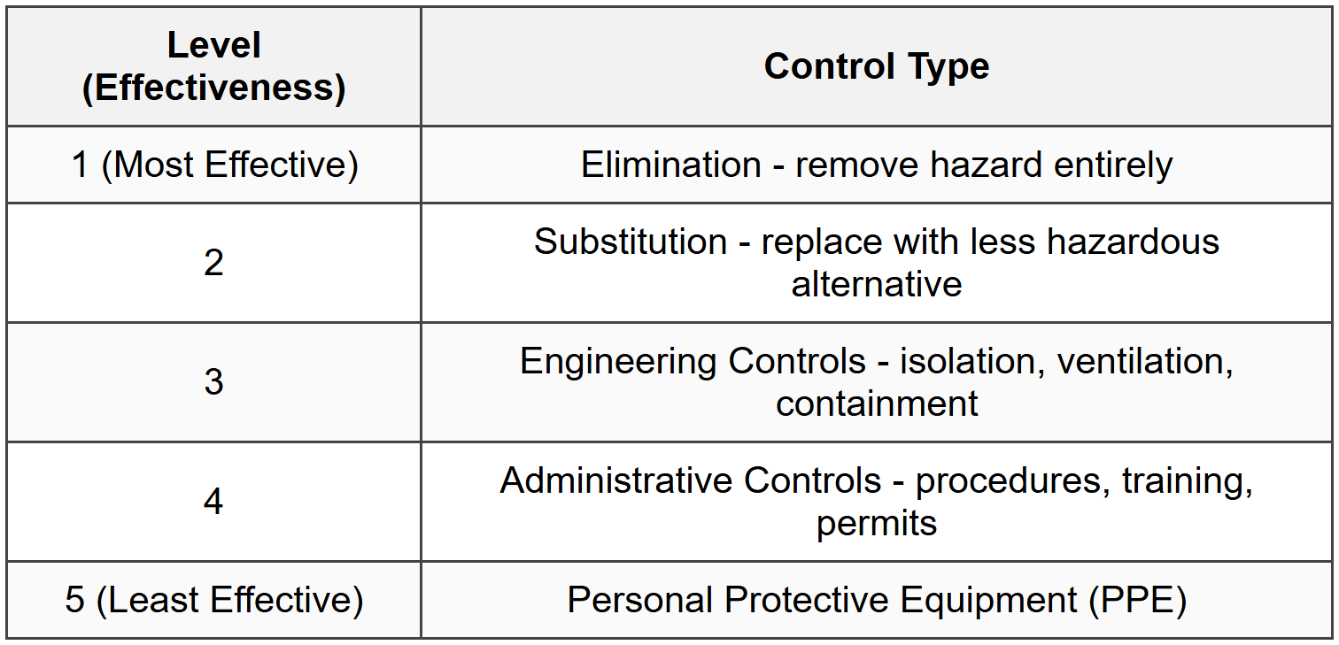
4.3 Hierarchy of Controls
4.4 Design for Operability
- Minimize human intervention requirements
- Provide clear indication of operating status
- Design for ease of maintenance and inspection
- Incorporate error-proofing (poka-yoke) mechanisms
- Allow safe shutdown and restart procedures
5. Fire and Explosion Hazards
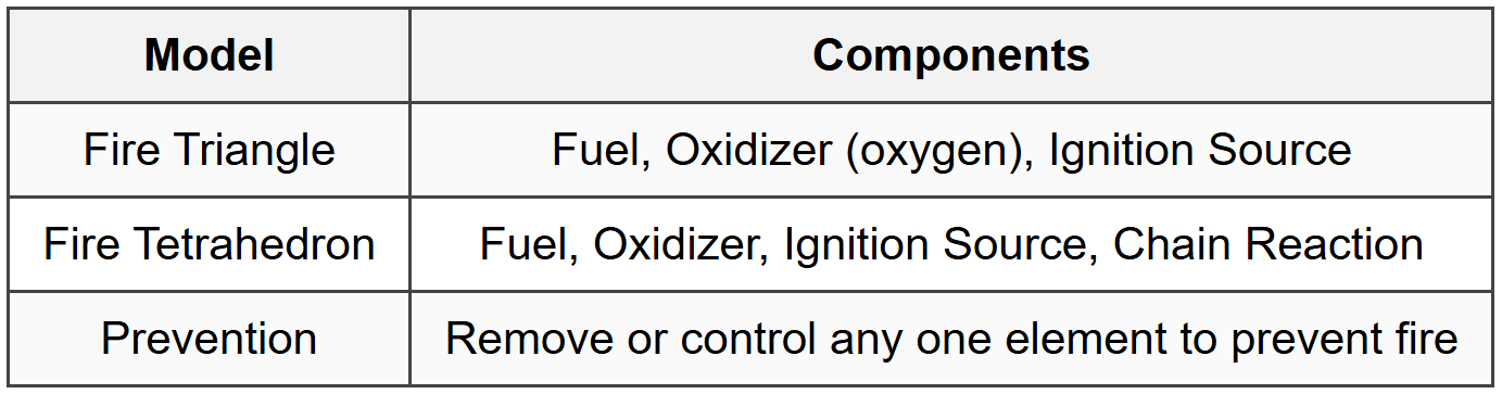
5.1 Fire Triangle and Fire Tetrahedron
5.2 Flammability Limits
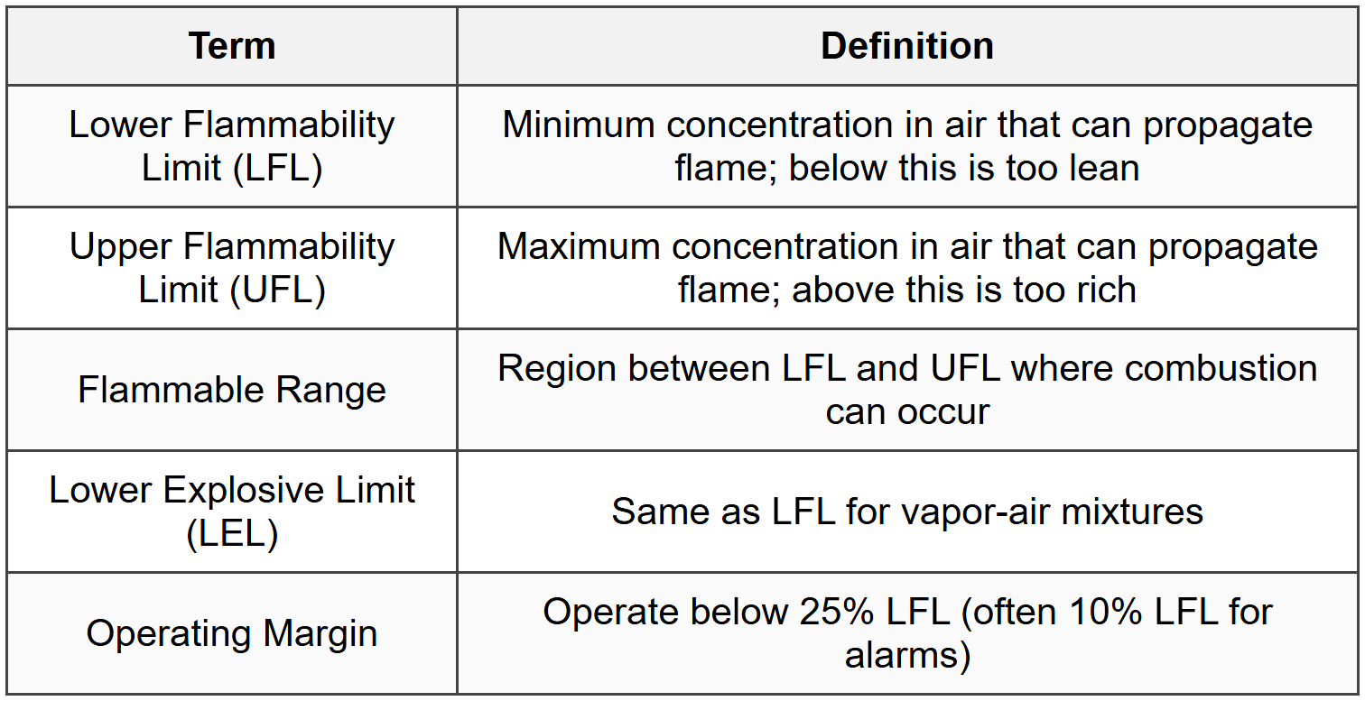
5.2.1 Factors Affecting Flammability Limits
- Temperature increase: widens flammable range (lowers LFL, raises UFL)
- Pressure increase: widens flammable range
- Oxygen enrichment: significantly widens range and increases hazard
- Inert gas addition: narrows range; can prevent combustion
5.3 Ignition Energy and Autoignition

5.4 Dust Explosions

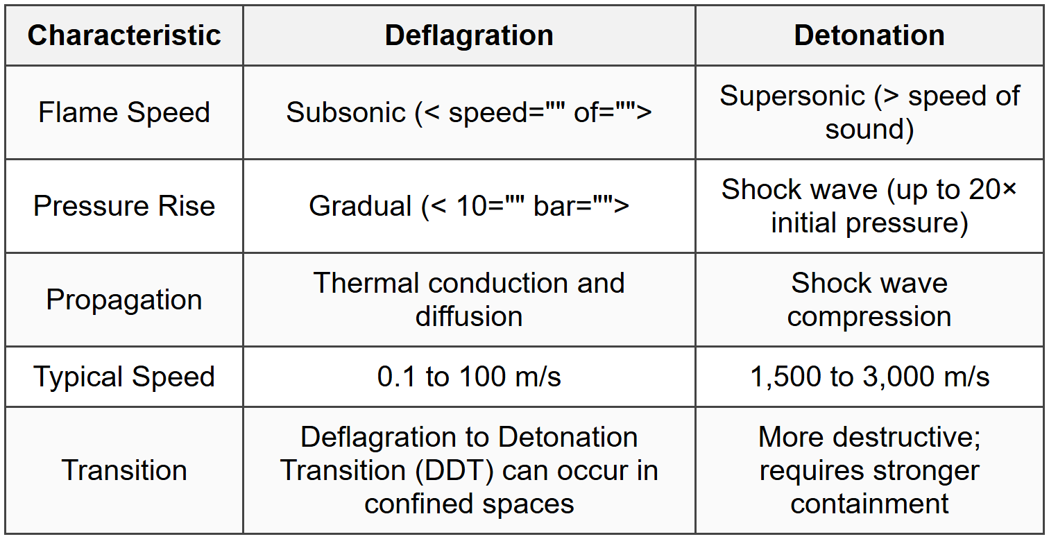
5.5 Deflagration vs. Detonation
5.6 Explosion Protection Methods

5.7 BLEVE (Boiling Liquid Expanding Vapor Explosion)

6. Pressure Relief and Emergency Venting
6.1 Pressure Relief Device Types

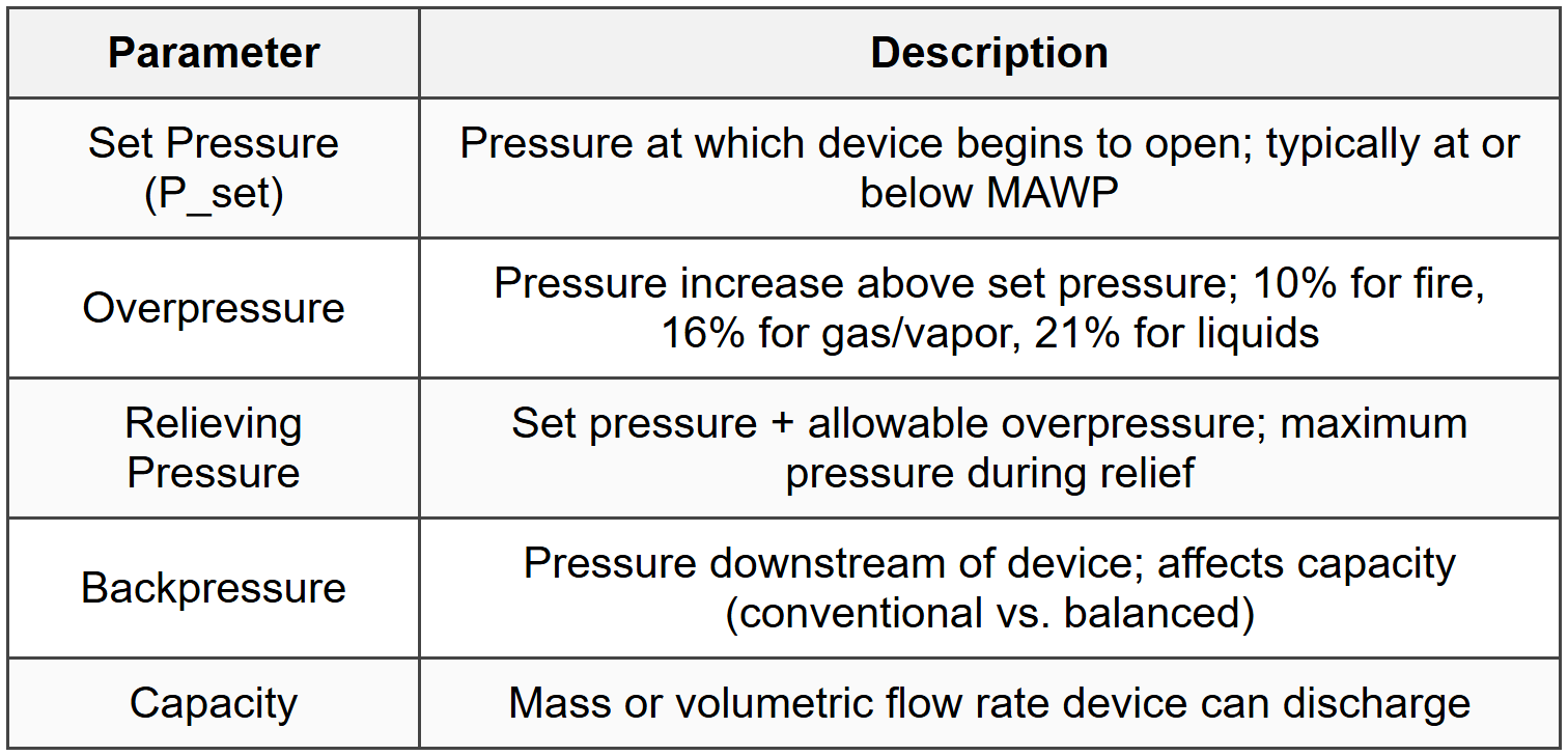
6.2 Relief Device Sizing Parameters
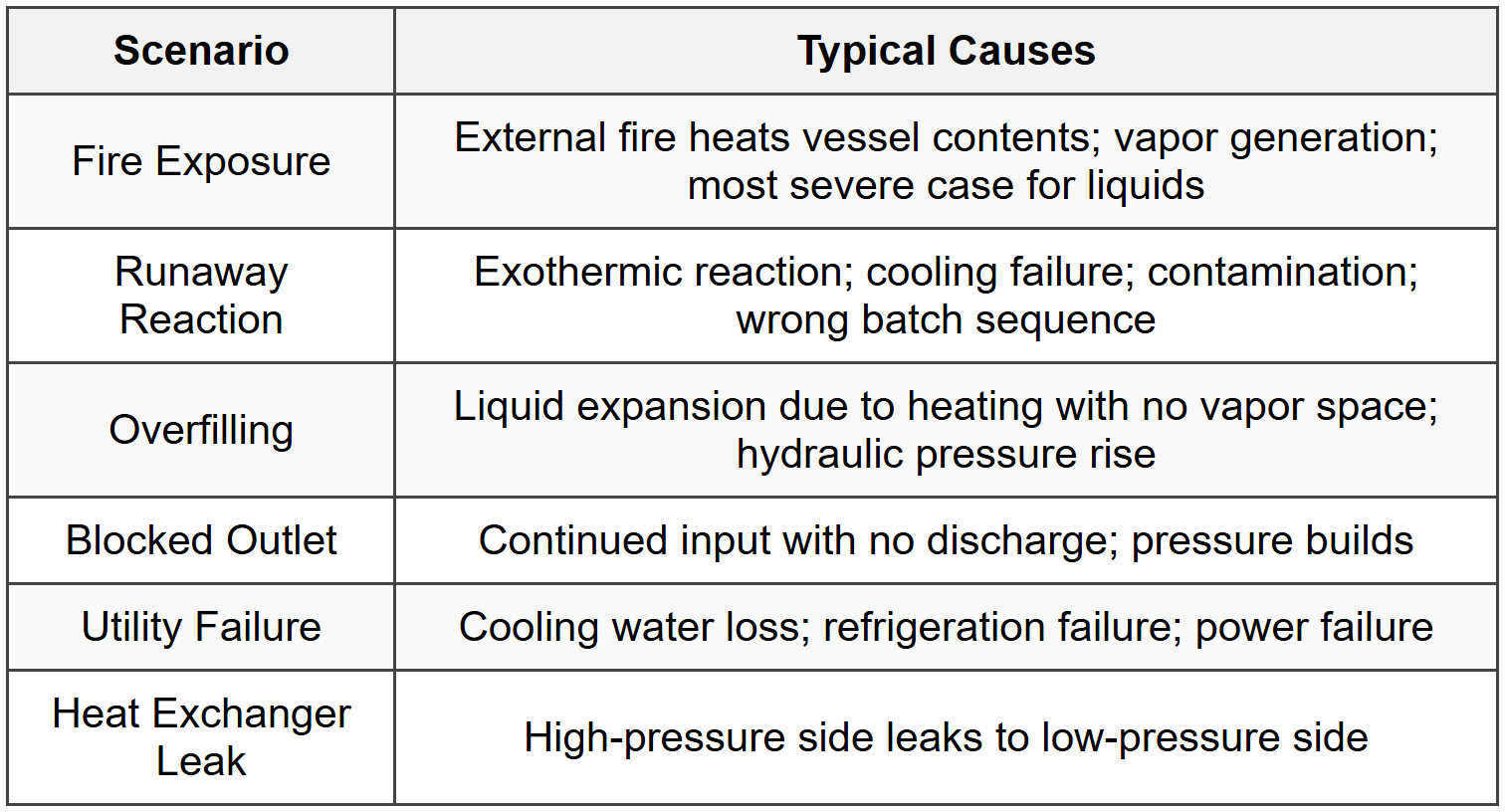
6.3 Relief Scenarios
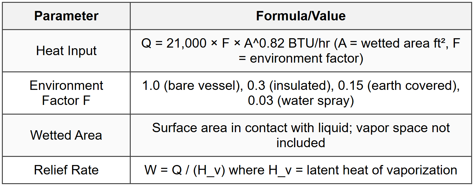
6.4 Fire Relief Sizing (API 520/521)
6.5 Gas and Vapor Relief Sizing
- Critical flow (choked): occurs when P_downstream/P_upstream ≤ critical pressure ratio
- Critical pressure ratio = [2/(k+1)]^[k/(k-1)] where k = C_p/C_v
- For ideal gas: W = C × A × P × sqrt(M / (Z × T)) where C = discharge coefficient
- Required orifice area: A = W / (C × K_d × P × K_b × K_c) (API 520 equation)
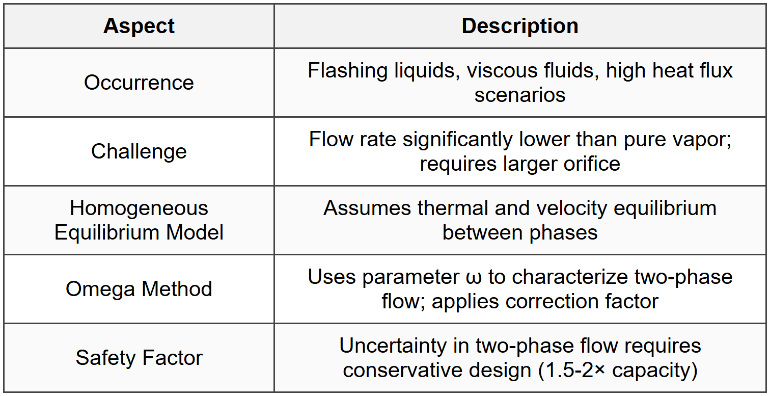
6.6 Two-Phase Flow Relief
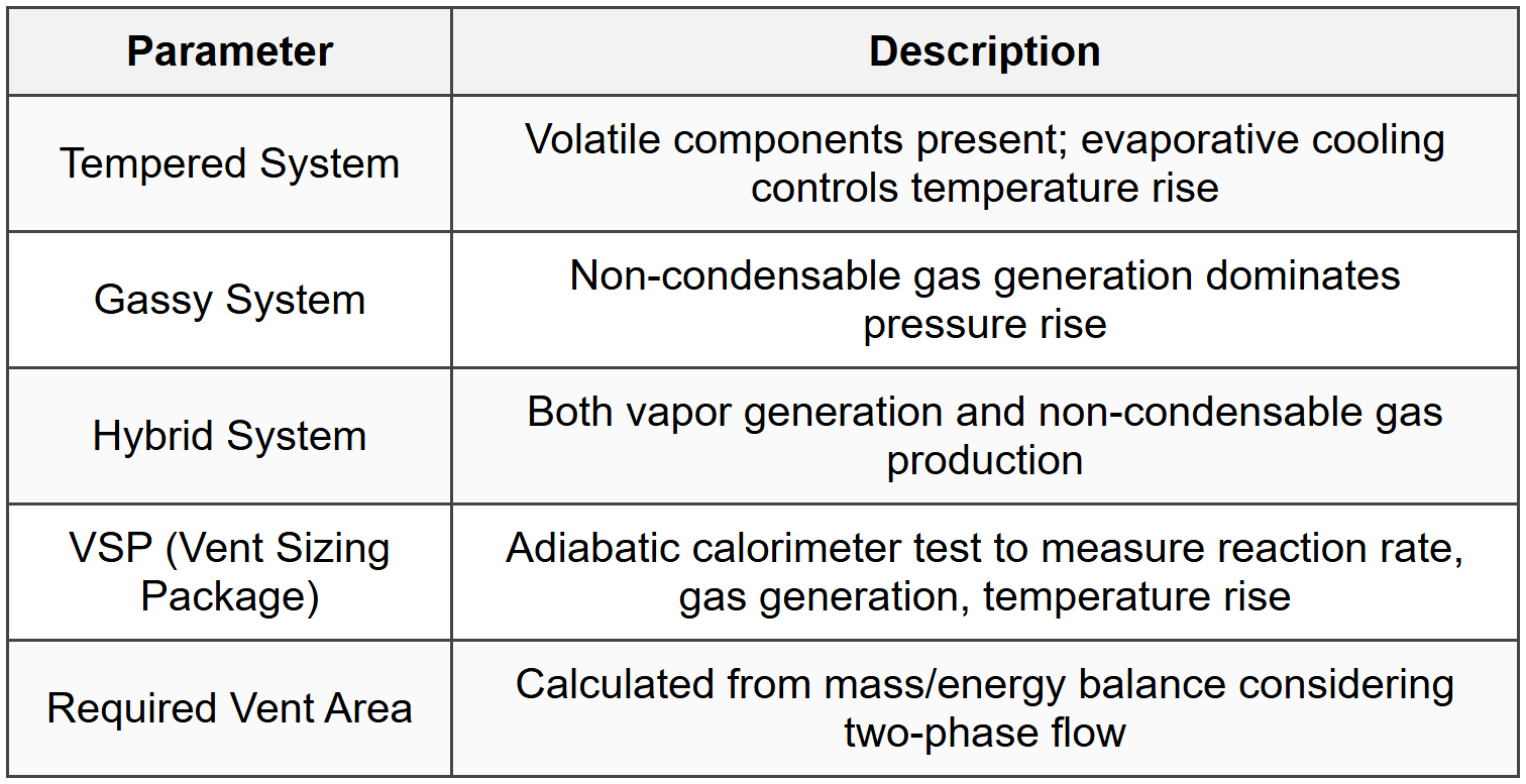
6.7 Reaction Runaway Relief (DIERS Methodology)
6.8 Relief System Design Considerations
- Inlet piping: minimize length and fittings; typically < 3%="" pressure="">
- Outlet piping: size to prevent excessive backpressure; consider reaction forces
- Disposal: containment system (scrubber, flare, catch tank) for hazardous materials
- Multiple devices: only one required to be sized for single contingency (API 521)
- Inspection and testing: regular testing required (typically 5-10 years for valves)
7. Toxicity and Chemical Exposure
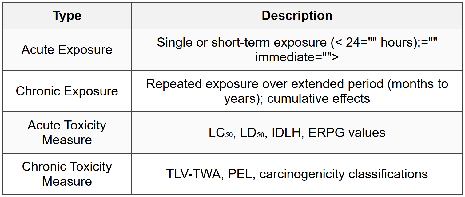
7.1 Acute vs. Chronic Exposure
7.2 Routes of Exposure

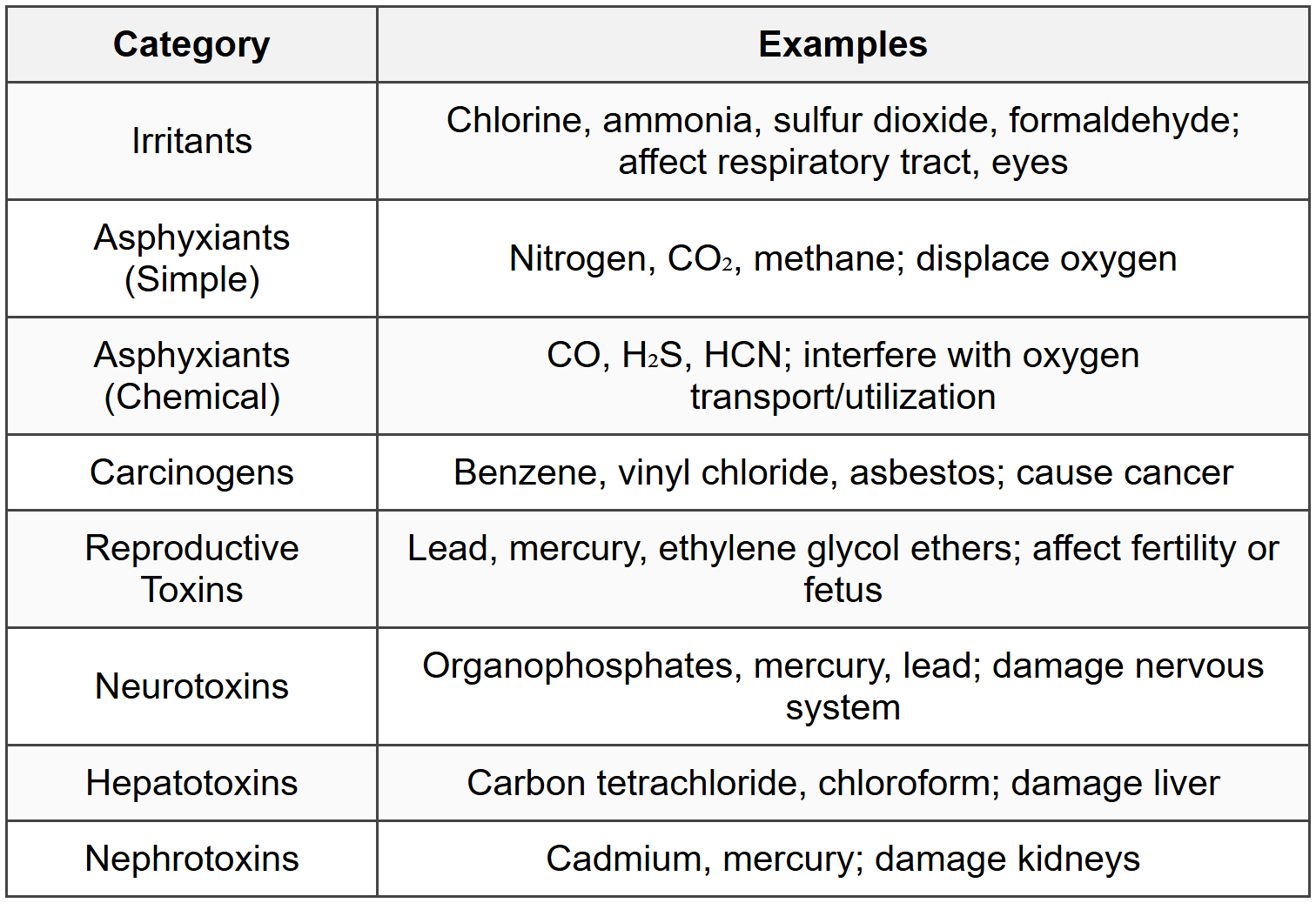
7.3 Toxic Effect Categories
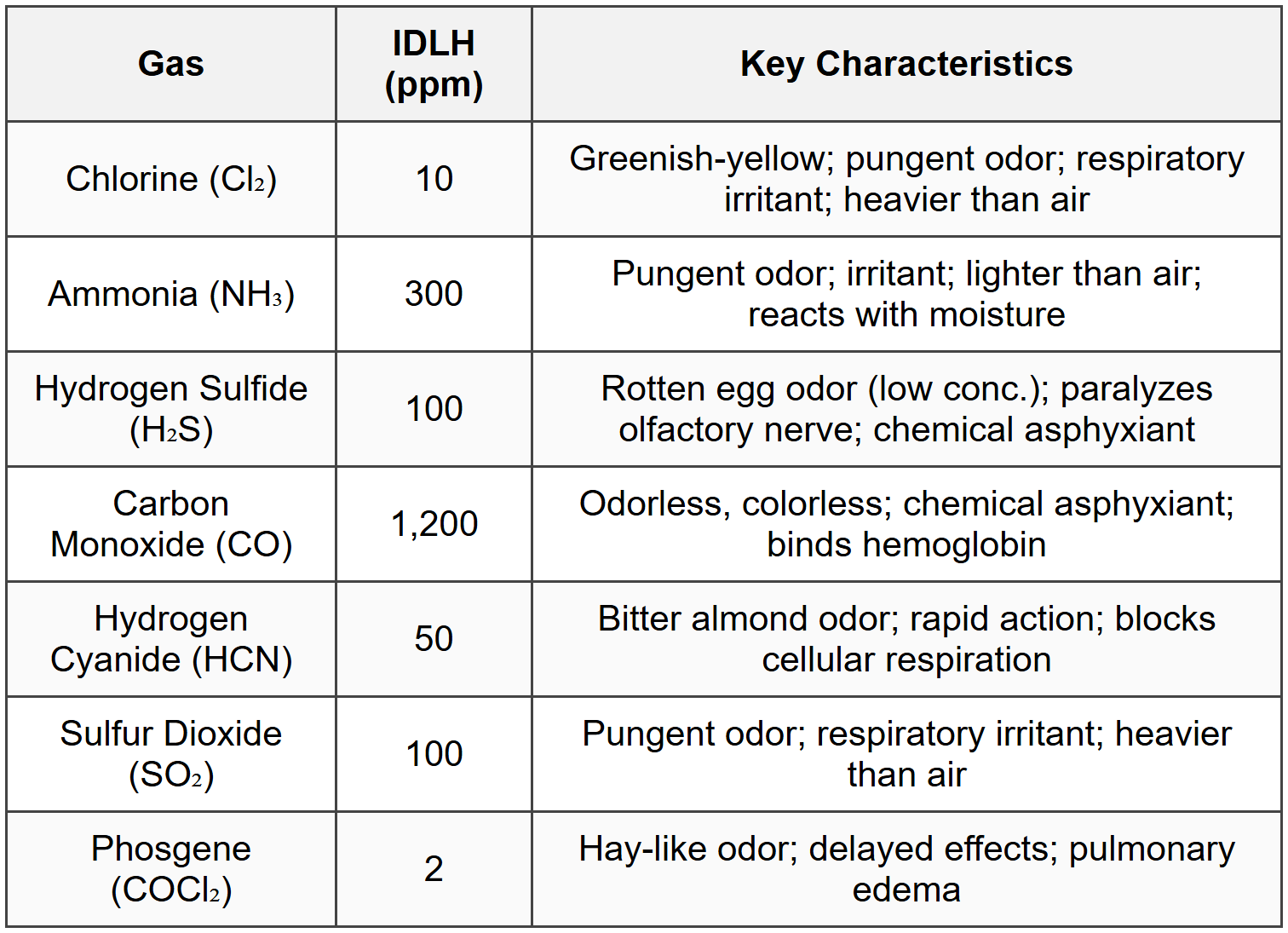
7.4 Specific Toxic Gases
7.5 Chemical Hazard Classification (GHS)

7.6 Atmospheric Dispersion of Toxic Releases

8. Process Safety Management Elements
8.1 OSHA PSM Regulation (29 CFR 1910.119)

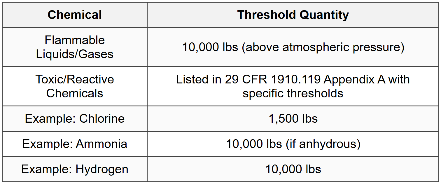
8.2 PSM Coverage Thresholds
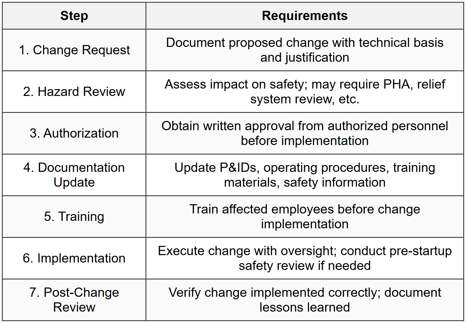
8.3 Management of Change (MOC)
8.3.1 Changes Not Requiring MOC
- Replacements-in-kind (same specification, no performance change)
- Changes already covered by existing procedures
- Changes that do not affect safety (case-by-case determination)
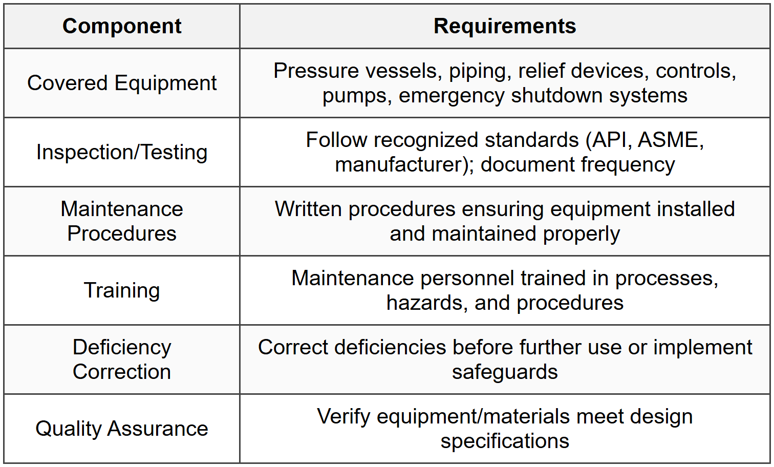
8.4 Mechanical Integrity Program
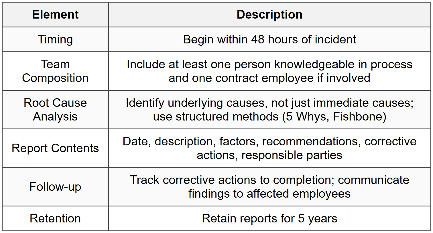
8.5 Incident Investigation
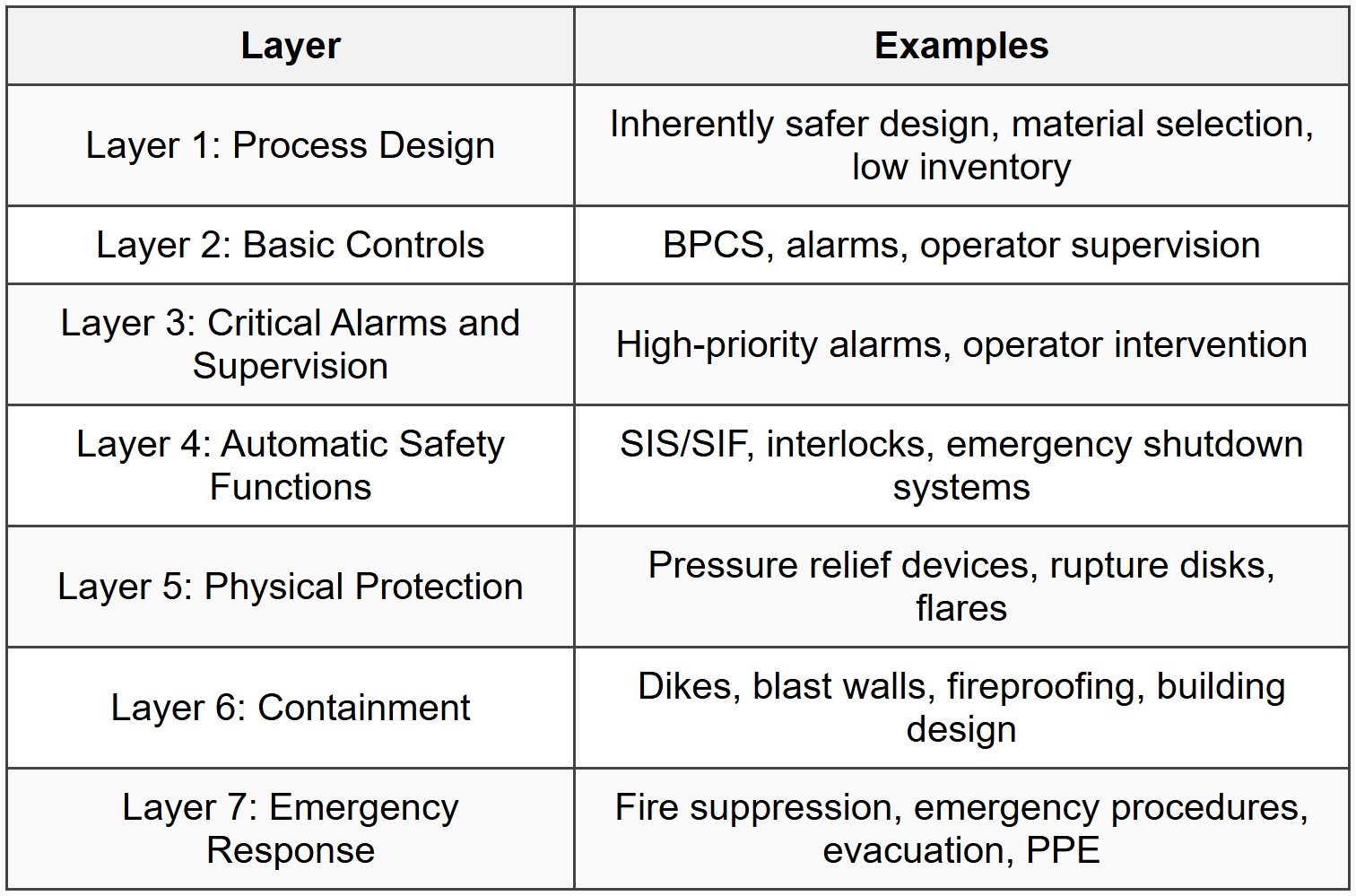
8.6 Layers of Protection (Swiss Cheese Model)
9. Static Electricity and Bonding/Grounding
9.1 Static Electricity Generation

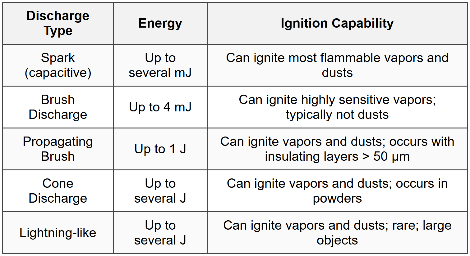
9.2 Ignition from Static Electricity
9.3 Conditions for Static Ignition Hazard
- Charge generation (flow, agitation, filling, separation)
- Charge accumulation on conductive object (isolated conductor)
- Flammable atmosphere present within flammable range
- Discharge energy exceeds MIE of flammable material (typically 0.01-10 mJ)
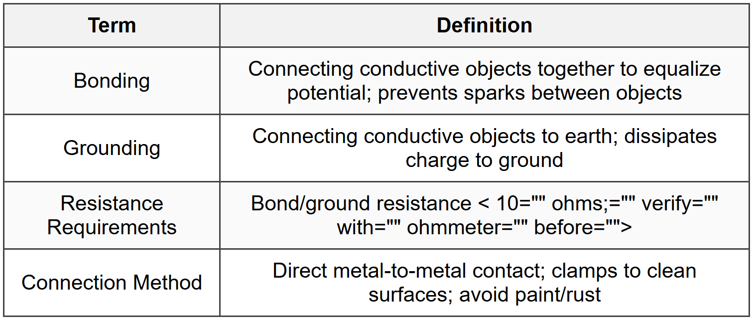
9.4 Bonding and Grounding
9.5 Static Hazards in Specific Operations

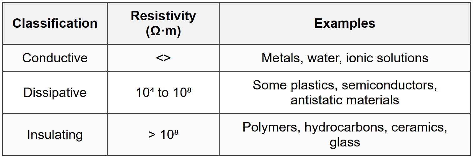
9.6 Material Conductivity Classification
9.7 Static Control Methods
- Bond and ground all conductive equipment and containers
- Avoid insulating materials (use conductive or dissipative alternatives)
- Reduce flow velocity (< 1="" m/s="" for="" low="" conductivity="" liquids;="">< 7="" m/s="" for="">
- Increase humidity (> 50% RH reduces charge accumulation)
- Allow relaxation time (30 seconds to 10 minutes depending on conductivity)
- Use conductive footwear and flooring in hazardous areas
- Avoid splash filling; use dip pipes extending to tank bottom
- Inert atmosphere (prevents ignition even if discharge occurs)
9.8 Relaxation Time

The document Cheatsheet: Hazard Analysis is a part of the PE Exam Course Chemical Engineering for PE.
All you need of PE Exam at this link: PE Exam
About this Document

Apr 20, 2026 Last updated
Related Exams
Document Description: Cheatsheet: Hazard Analysis for PE Exam 2026 is part of Chemical Engineering for PE preparation. The notes and questions for Cheatsheet: Hazard Analysis have been prepared according to the PE Exam exam syllabus. Information about Cheatsheet: Hazard Analysis covers topics like and Cheatsheet: Hazard Analysis Example, for PE Exam 2026 Exam. Find important definitions, questions, notes, meanings, examples, exercises and tests below for Cheatsheet: Hazard Analysis.
Introduction of Cheatsheet: Hazard Analysis in English is available as part of our Chemical Engineering for PE for PE Exam & Cheatsheet: Hazard Analysis in Hindi for Chemical Engineering for PE course. Download more important topics related with notes, lectures and mock test series for PE Exam Exam by signing up for free. PE Exam: Cheatsheet: Hazard Analysis
Description
Cheatsheet: Hazard Analysis of Chemical Engineering to help you remember important concepts with short tricks. Start learning for PE Exam exam & improve retention with EduRev.
Information about Cheatsheet: Hazard Analysis
In this doc you can find the meaning of Cheatsheet: Hazard Analysis defined & explained in the simplest way possible. Besides explaining types of Cheatsheet: Hazard Analysis theory, EduRev gives you an ample number of questions to practice Cheatsheet: Hazard Analysis tests, examples and also practice PE Exam tests
Top Courses for PE Exam
Related Searches
mock tests for examination, Summary, practice quizzes, Free, Previous Year Questions with Solutions, shortcuts and tricks, Semester Notes, Extra Questions, Important questions, video lectures, Cheatsheet: Hazard Analysis, Viva Questions, Exam, study material, ppt, MCQs, Cheatsheet: Hazard Analysis, pdf , Sample Paper, past year papers, Objective type Questions, Cheatsheet: Hazard Analysis;