NCERT Solutions Class 12 Physics Chapter 7 - Alternating Current

Page No. 200
Q7.1: A 100 Ω resistor is connected to a 220 V, 50 Hz ac supply.
(a) What is the rms value of current in the circuit?
(b) What is the net power consumed over a full cycle?
Ans: Resistance of the resistor, R = 100 Ω
Supply voltage, V = 220 V
Frequency, ν = 50 Hz
(a) The rms value of current in the circuit is given as:
(b) The net power consumed over a full cycle is given as:
P = VI
= 220 × 2.2 = 484 W
Q7.2: (a) The peak voltage of an ac supply is 300 V. What is the rms voltage?
(b) The rms value of current in an ac circuit is 10 A. What is the peak current?
Ans: (a) Peak voltage of the ac supply, V0 = 300 V
Rms voltage is given as:
(b) The rms value of current is given as:
I = 10 A
Now, peak current is given as:
Q7.3: A 44 mH inductor is connected to 220 V, 50 Hz ac supply. Determine the rms value of the current in the circuit.
Ans: Inductance of inductor, L = 44 mH = 44 × 10−3 H
Supply voltage, V = 220 V
Frequency, ν = 50 Hz
Angular frequency, ω= 
Inductive reactance, XL = ω L
Rms value of current is given as:
Hence, the rms value of current in the circuit is 15.92 A.
Q7.4: A 60 μF capacitor is connected to a 110 V, 60 Hz ac supply. Determine the rms value of the current in the circuit.
Ans: Capacitance of capacitor, C = 60 μF = 60 × 10−6 F
Supply voltage, V = 110 V
Frequency, ν = 60 Hz
Angular frequency, ω=
Capacitive reactance 
Rms value of current is given as:
Hence, the rms value of current is 2.49 A.
Q7.5: In Exercises 7.3 and 7.4, what is the net power absorbed by each circuit over a complete cycle. Explain your answer.
Ans: In the inductive circuit,
Rms value of current, I = 15.92 A
Rms value of voltage, V = 220 V
Hence, the net power absorbed can be obtained by the relation,
P = VI cos Φ
Where,
Φ = Phase difference between V and I
In a pure inductive circuit, the phase difference between alternating voltage and current is 90°, meaning that the current lags the voltage by 90°.
Hence, P = 0 i.e., the net power is zero.
In the capacitive circuit,
Rms value of current, I = 2.49 A
Rms value of voltage, V = 110 V
Hence, the net power absorbed can be obtained as:
P = VI Cos Φ
For a pure capacitive circuit, the phase difference between alternating voltage and current is 90° i.e., Φ= 90°.
Hence, P = 0 i.e., the net power is zero.
Ques 7.6: A charged 30 μF capacitor is connected to a 27 mH inductor. What is the angular frequency of free oscillations of the circuit?
Ans: Capacitance, C = 30μF = 30×10−6F
Inductance, L = 27 mH = 27 × 10−3 H
Angular frequency is given as:
Hence, the angular frequency of free oscillations of the circuit is 1.11 × 10³ rad/s.
Q7.7: A series LCR circuit with R = 20 Ω, L = 1.5 H and C = 35 μF is connected to a variable-frequency 200 V ac supply. When the frequency of the supply equals the natural frequency of the circuit, what is the average power transferred to the circuit in one complete cycle?
Ans: At resonance, the frequency of the supply power equals the natural frequency of the given LCR circuit.
Resistance, R = 20 Ω
Inductance, L = 1.5 H
Capacitance, C = 35 μF = 30 × 10−6 F
AC supply voltage to the LCR circuit, V = 200 V
Impedance of the circuit is given by the relation,
At resonance,
Current in the circuit can be calculated as:
Thus, the average power transferred to the circuit in one complete cycle is calculated as P = VI
= 200 × 10 = 2000 W.
Q7.8: Figure 7.21 shows a series LCR circuit connected to a variable frequency 230 V source. L = 5.0 H, C = 80μF, R = 40 Ω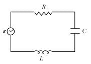
(a) Determine the source frequency which drives the circuit in resonance.
(b) Obtain the impedance of the circuit and the amplitude of current at the resonating frequency.
(c) Determine the rms potential drops across the three elements of the circuit. Show that the potential drop across the LC combination is zero at the resonating frequency.
Ans: Inductance of the inductor, L = 5.0 H
Capacitance of the capacitor, C = 80 μH = 80 × 10−6 F
Resistance of the resistor, R = 40 Ω
Potential of the variable voltage source, V = 230 V
(a) Resonance angular frequency is given as:
Hence, the circuit will come in resonance for a source frequency of 50 rad/s.
(b) Impedance of the circuit is given by the relation,
At resonance,
Amplitude of the current at the resonating frequency is given as: 
Where,
V0 = Peak voltage
Hence, at resonance, the impedance of the circuit is 40 Ω and the amplitude of the current is 8.13 A.
(c) Rms potential drop across the inductor,
(VL)rms = I × ωRL
Where,
I = rms current
Potential drop across the capacitor,
Potential drop across the resistor,
(VR)rms = IR
=  × 40 = 230 V
Potential drop across the LC combination,
At resonance,
∴VLC = 0
Hence, it is proved that the potential drop across the LC combination is zero at resonating frequency.
Old NCERT Solutions
Q1: An LC circuit contains a 20 mH inductor and a 50 μF capacitor with an initial charge of 10 mC. The resistance of the circuit is negligible. Let the instant the circuit is closed be t = 0.
(a) What is the total energy stored initially? Is it conserved during LC oscillations?
(b) What is the natural frequency of the circuit?
(c) At what time is the energy stored
(i) completely electrical (i.e., stored in the capacitor)?
(ii) completely magnetic (i.e., stored in the inductor)?
(d) At what times is the total energy shared equally between the inductor and the capacitor?
(e) If a resistor is inserted in the circuit, how much energy is eventually dissipated as heat?
Ans: Inductance of the inductor, L = 20 mH = 20 × 10−3 H
Capacitance of the capacitor, C = 50 μF = 50 × 10−6 F
Initial charge on the capacitor, Q = 10 mC = 10 × 10−3 C
(a) Total energy stored initially in the circuit is given as:
Hence, the total energy stored in the LC circuit will be conserved because there is no resistor connected in the circuit.
(b) Natural frequency of the circuit is given by the relation,
Natural angular frequency,
Hence, the natural frequency of the circuit is 103 rad/s.
(c) (i) For time period (T ), the total charge on the capacitor at time t,
For energy stored is electrical, we can write Q’ = Q.
Hence, it can be inferred that the energy stored in the capacitor is completely electrical at time, t =
(ii) Magnetic energy is the maximum when electrical energy, Q′ is equal to 0.
Hence, it can be inferred that the energy stored in the capacitor is completely magnetic at time, 
(d) Q1 = Charge on the capacitor when total energy is equally shared between the capacitor and the inductor at time t.
When total energy is equally shared between the inductor and capacitor, the energy stored in the capacitor =  (maximum energy).
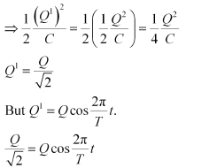
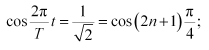
where n = 0, 1, 2, .....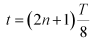
Hence, total energy is equally shared between the inductor and the capacity at time, 
(e) If a resistor is inserted in the circuit, then total initial energy is dissipated as heat energy in the circuit. The resistance damps out the LC oscillation.
Q2: A coil of inductance 0.50 H and resistance 100 Ω is connected to a 240 V, 50 Hz ac supply.
(a) What is the maximum current in the coil?
(b) What is the time lag between the voltage maximum and the current maximum?
Ans: Inductance of the inductor, L = 0.50 H
Resistance of the resistor, R = 100 Ω
Potential of the supply voltage, V = 240 V
Frequency of the supply, ν = 50 Hz
(a) Peak voltage is given as:
Angular frequency of the supply,
ω = 2 πν
= 2π × 50 = 100 π rad/s
Maximum current in the circuit is given as:
(b) Equation for voltage is given as:
V = V0 cos ωt
Equation for current is given as:
I = I0 cos (ωt − Φ)
Where,
Φ = Phase difference between voltage and current
At time, t = 0.
V = V0(voltage is maximum)
For ωt − Φ = 0 i.e., at time ,
,
I = I0 (current is maximum)
Hence, the time lag between maximum voltage and maximum current is .
.
Now, phase angle Φ is given by the relation,
Hence, the time lag between maximum voltage and maximum current is 3.2 ms.
Q3: Obtain the answers (a) to (b) in Exercise 7.13 if the circuit is connected to a high frequency supply (240 V, 10 kHz). Hence, explain the statement that at very high frequency, an inductor in a circuit nearly amounts to an open circuit. How does an inductor behave in a dc circuit after the steady state?
Ans: Inductance of the inductor, L = 0.5 Hz
Resistance of the resistor, R = 100 Ω
Potential of the supply voltages, V = 240 V
Frequency of the supply,ν = 10 kHz = 104 Hz
Angular frequency, ω = 2πν= 2π × 104 rad/s
(a) Peak voltage, 
Maximum current, 
(b) For phase differenceΦ, we have the relation:
It can be observed that I0 is very small in this case. Hence, at high frequencies, the inductor amounts to an open circuit.
In a dc circuit, after a steady state is achieved, ω = 0. Hence, inductor L behaves like a pure conducting object.
Q4: A 100 μF capacitor in series with a 40 Ω resistance is connected to a 110 V, 60 Hz supply.
(a) What is the maximum current in the circuit?
(b) What is the time lag between the current maximum and the voltage maximum?
Ans: Capacitance of the capacitor, C = 100 μF = 100 × 10−6 F
Resistance of the resistor, R = 40 Ω
Supply voltage, V = 110 V
(a) Frequency of oscillations, ν= 60 Hz
Angular frequency, 
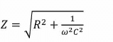
For a RC circuit, we have the relation for impedance as:
 Peak voltage, V0 =
Maximum current is given as:
(b) In a capacitor circuit, the voltage lags behind the current by a phase angle of Φ. This angle is given by the relation: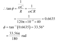
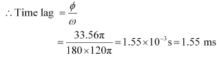
Hence, the time lag between maximum current and maximum voltage is 1.55 ms.
Q5: Obtain the answers to (a) and (b) in Exercise 7.15 if the circuit is connected to a 110 V, 12 kHz supply? Hence, explain the statement that a capacitor is a conductor at very high frequencies. Compare this behaviour with that of a capacitor in a dc circuit after the steady state.
Ans: Capacitance of the capacitor, C = 100 μF = 100 × 10−6 F
Resistance of the resistor, R = 40 Ω
Supply voltage, V = 110 V
Frequency of the supply, ν = 12 kHz = 12 × 103 Hz
Angular Frequency, ω = 2 πν= 2 × π × 12 × 10303
= 24π × 103 rad/s
Peak voltage, 
Maximum current, 
For an RC circuit, the voltage lags behind the current by a phase angle of Φ given as: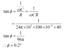
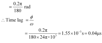
Hence, Φ tends to become zero at high frequencies. At a high frequency, capacitor C acts as a conductor.
In a dc circuit, after the steady state is achieved, ω = 0. Hence, capacitor C amounts to an open circuit.
Q6: Keeping the source frequency equal to the resonating frequency of the series LCR circuit, if the three elements, L, C and R are arranged in parallel, show that the total current in the parallel LCR circuit is minimum at this frequency. Obtain the current rms value in each branch of the circuit for the elements and source specified in Exercise 7.11 for this frequency.
Ans: An inductor (L), a capacitor (C), and a resistor (R) is connected in parallel with each other in a circuit where,
L = 5.0 H
C = 80 μF = 80 × 10−6 F
R = 40 Ω
Potential of the voltage source, V = 230 V
Impedance (Z) of the given parallel LCR circuit is given as:
Where,
ω = Angular frequency
At resonance,
Hence, the magnitude of Z is the maximum at 50 rad/s. As a result, the total current is minimum.
Rms current flowing through inductor L is given as:
Rms current flowing through capacitor C is given as:
Rms current flowing through resistor R is given as:
Q7: A circuit containing a 80 mH inductor and a 60 μF capacitor in series is connected to a 230 V, 50 Hz supply. The resistance of the circuit is negligible.
(a) Obtain the current amplitude and rms values.
(b) Obtain the rms values of potential drops across each element.
(c) What is the average power transferred to the inductor?
(d) What is the average power transferred to the capacitor?
(e) What is the total average power absorbed by the circuit? [‘Average’ implies ‘averaged over one cycle’.]
Ans: Inductance, L = 80 mH = 80 × 10−3 H
Capacitance, C = 60 μF = 60 × 10−6 F
Supply voltage, V = 230 V
Frequency, ν = 50 Hz
Angular frequency, ω = 2πν= 100 π rad/s
Peak voltage, V0 = 
(a) Maximum current is given as:
The negative sign appears because 
Amplitude of maximum current, 
Hence, rms value of current, 
(b) Potential difference across the inductor,
VL= I × ωL
= 8.22 × 100 π × 80 × 10−3
= 206.61 V
Potential difference across the capacitor,
(c) Average power consumed by the inductor is zero as actual voltage leads the current by .
.
(d) Average power consumed by the capacitor is zero as voltage lags current by.
(e) The total power absorbed (averaged over one cycle) is zero.
Q8: Suppose the circuit in Exercise 7.18 has a resistance of 15 Ω. Obtain the average power transferred to each element of the circuit, and the total power absorbed.
Ans: Average power transferred to the resistor = 788.44 W
Average power transferred to the capacitor = 0 W
Total power absorbed by the circuit = 788.44 W
Inductance of inductor, L = 80 mH = 80 × 10−3 H
Capacitance of capacitor, C = 60 μF = 60 × 10−6 F
Resistance of resistor, R = 15 Ω
Potential of voltage supply, V = 230 V
Frequency of signal, ν = 50 Hz
Angular frequency of signal, ω = 2πν= 2π × (50) = 100π rad/s
The elements are connected in series to each other.
Hence, impedance of the circuit is given as:
Current flowing in the circuit, 
Average power transferred to resistance is given as:
PR= I2R
= (7.25)2 × 15 = 788.44 W
Average power transferred to capacitor, PC = Average power transferred to inductor, PL = 0
Total power absorbed by the circuit:
= PR + PC + PL
= 788.44 + 0 + 0 = 788.44 W
Hence, the total power absorbed by the circuit is 788.44 W.
Q9: A series LCR circuit with L = 0.12 H, C = 480 nF, R = 23 Ω is connected to a 230 V variable frequency supply.
(a) What is the source frequency for which current amplitude is maximum. Obtain this maximum value.
(b) What is the source frequency for which average power absorbed by the circuit is maximum. Obtain the value of this maximum power.
(c) For which frequencies of the source is the power transferred to the circuit half the power at resonant frequency? What is the current amplitude at these frequencies?
(d) What is the Q-factor of the given circuit?
Ans: Inductance, L = 0.12 H
Capacitance, C = 480 nF = 480 × 10−9 F
Resistance, R = 23 Ω
Supply voltage, V = 230 V
Peak voltage is given as:
V0 =  = 325.22 V
(a) Current flowing in the circuit is given by the relation, 
Where,
I0 = maximum at resonance
At resonance, we have
Where,
ωR = Resonance angular frequency
∴Resonant frequency, 
And, maximum current 
(b) Maximum average power absorbed by the circuit is given as:
Hence, resonant frequency (VR) is 
(c) The power transferred to the circuit is half the power at resonant frequency.
Frequencies at which power transferred is half, = 
Where,
Hence, change in frequency, 
∴
And, 
Hence, at 648.22 Hz and 678.74 Hz frequencies, the power transferred is half.
At these frequencies, current amplitude can be given as:
(d) Q-factor of the given circuit can be obtained using the relation, 
Hence, the Q-factor of the given circuit is 21.74.
Q10: Obtain the resonant frequency and Q-factor of a series LCR circuit with L = 3.0 H, C = 27 μF, and R = 7.4 Ω. It is desired to improve the sharpness of the resonance of the circuit by reducing its ‘full width at half maximum’ by a factor of 2. Suggest a suitable way.
Ans: Inductance, L = 3.0 H
Capacitance, C = 27 μF = 27 × 10−6 F
Resistance, R = 7.4 Ω
At resonance, angular frequency of the source for the given LCR series circuit is given as:
Q-factor of the series:
To improve the sharpness of the resonance by reducing its ‘full width at half maximum’ by a factor of 2 without changing , we need to reduce R to half i.e.,
Resistance =
Q11: Answer the following questions:
(a) In any ac circuit, is the applied instantaneous voltage equal to the algebraic sum of the instantaneous voltages across the series elements of the circuit? Is the same true for rms voltage?
(b) A capacitor is used in the primary circuit of an induction coil.
(c) An applied voltage signal consists of a superposition of a dc voltage and an ac voltage of high frequency. The circuit consists of an inductor and a capacitor in series. Show that the dc signal will appear across C and the ac signal across L.
(d) A choke coil in series with a lamp is connected to a dc line. The lamp is seen to shine brightly. Insertion of an iron core in the choke causes no change in the lamp’s brightness. Predict the corresponding observations if the connection is to an ac line.
(e) Why is choke coil needed in the use of fluorescent tubes with ac mains? Why can we not use an ordinary resistor instead of the choke coil?
Ans: (a) Yes; the statement is not true for rms voltage
It is true that in any ac circuit, the applied voltage is equal to the average sum of the instantaneous voltages across the series elements of the circuit. However, this is not true for rms voltage because voltages across different elements may not be in phase.
(b) High induced voltage is used to charge the capacitor.
A capacitor is used in the primary circuit of an induction coil. This is because when the circuit is broken, a high induced voltage is used to charge the capacitor to avoid sparks.
(c) The dc signal will appear across capacitor C because for dc signals, the impedance of an inductor (L) is negligible while the impedance of a capacitor (C) is very high (almost infinite). Hence, a dc signal appears across C. For an ac signal of high frequency, the impedance of L is high and that of C is very low. Hence, an ac signal of high frequency appears across L.
(d) If an iron core is inserted in the choke coil (which is in series with a lamp connected to the ac line), then the lamp will glow dimly. This is because the choke coil and the iron core increase the impedance of the circuit.
(e) A choke coil is needed in the use of fluorescent tubes with ac mains because it reduces the voltage across the tube without wasting much power. An ordinary resistor cannot be used instead of a choke coil for this purpose because it wastes power in the form of heat.
Q12: A power transmission line feeds input power at 2300 V to a stepdown transformer with its primary windings having 4000 turns. What should be the number of turns in the secondary in order to get output power at 230 V?
Ans : Input voltage, V1 = 2300
Number of turns in primary coil, n1 = 4000
Output voltage, V2 = 230 V
Number of turns in secondary coil = n2
Voltage is related to the number of turns as:
Hence, there are 400 turns in the second winding.
Q13: At a hydroelectric power plant, the water pressure head is at a height of 300 m and the water flow available is 100 m3 s−1. If the turbine generator efficiency is 60%, estimate the electric power available from the plant (g= 9.8 m s−2).
Ans: Height of water pressure head, h = 300 m
Volume of water flow per second, V = 100 m3/s
Efficiency of turbine generator, n = 60% = 0.6
Acceleration due to gravity, g = 9.8 m/s2
Density of water, ρ = 103 kg/m3
Electric power available from the plant = η × hρgV
= 0.6 × 300 × 103 × 9.8 × 100
= 176.4 × 10⁶ W
= 176.4 MW
Q14: A small town with a demand of 800 kW of electric power at 220 V is situated 15 km away from an electric plant generating power at 440 V. The resistance of the two wire line carrying power is 0.5 Ω per km. The town gets power from the line through a 4000-220 V step-down transformer at a sub-station in the town.
(a) Estimate the line power loss in the form of heat.
(b) How much power must the plant supply, assuming there is negligible power loss due to leakage?
(c) Characterise the step up transformer at the plant.
Ans: Total electric power required, P = 800 kW = 800 × 103 W
Supply voltage, V = 220 V
Voltage at which electric plant is generating power, V' = 440 V
Distance between the town and power generating station, d = 15 km
Resistance of the two wire lines carrying power = 0.5 Ω/km
Total resistance of the wires, R = (15 15)0.5 = 15 Ω
A step-down transformer of rating 4000 − 220 V is used in the sub-station.
Input voltage, V1 = 4000 V
Output voltage, V2 = 220 V
Rms current in the wire lines is given as:
(a) Line power loss = I2R
= (200)2 × 15
= 600 × 103 W
= 600 kW
(b) Assuming that the power loss is negligible due to the leakage of the current:
Total power supplied by the plant = 800 kW 600 kW
= 1400 kW
(c) Voltage drop in the power line = IR = 200 × 15 = 3000 V
Hence, total voltage transmitted from the plant = 3000 4000
= 7000 V
Also, the power generated is 440 V.
Hence, the rating of the step-up transformer situated at the power plant is 440 V − 7000 V.
Q15: Do the same exercise as above with the replacement of the earlier transformer by a 40,000-220 V step-down transformer (Neglect, as before, leakage losses though this may not be a good assumption any longer because of the very high voltage transmission involved). Hence, explain why high voltage transmission is preferred?
Ans: The rating of a step-down transformer is 40000 V−220 V.
Input voltage, V1 = 40000 V
Output voltage, V2 = 220 V
Total electric power required, P = 800 kW = 800 × 103 W
Source potential, V = 220 V
Voltage at which the electric plant generates power, V' = 440 V
Distance between the town and power generating station, d = 15 km
Resistance of the two wire lines carrying power = 0.5 Ω/km
Total resistance of the wire lines, R = (15 15)0.5 = 15 Ω
P = V1I
Rms current in the wire line is given as:
(a) Line power loss = I2R
= (20)2 × 15
= 6 kW
(b) Assuming that the power loss is negligible due to the leakage of current.
Hence, power supplied by the plant = 800 kW 6kW = 806 kW
(c) Voltage drop in the power line = IR = 20 × 15 = 300 V
Hence, voltage that is transmitted by the power plant
= 300 40000 = 40300 V
The power is being generated in the plant at 440 V.
Hence, the rating of the step-up transformer needed at the plant is
440 V − 40300 V.
Hence, power loss during transmission = 
In the previous exercise, the power loss due to the same reason is . Since the power loss is less for a high voltage transmission, high voltage transmissions are preferred for this purpose.
Q16: Obtain the resonant frequency ωr of a series LCR circuit with L = 2.0 H, C = 32 μF and R = 10 Ω. What is the Q-value of this circuit?
Ans: Inductance, L = 2.0 H
Capacitance, C = 32 μF = 32 × 10−6 F
Resistance, R = 10 Ω
Resonant frequency is given by the relation,
Now, Q-value of the circuit is given as:
Hence, the Q-Value of this circuit is 25.
Q17: Suppose the initial charge on the capacitor in Exercise 7.7 is 6 mC. What is the total energy stored in the circuit initially? What is the total energy at later time?
Ans: Capacitance of the capacitor, C = 30 μF = 30×10−6 F
Inductance of the inductor, L = 27 mH = 27 × 10−3 H
Charge on the capacitor, Q = 6 mC = 6 × 10⁻³ C
Total energy stored in the capacitor can be calculated by the relation,
Total energy at a later time will remain the same because energy is shared between the capacitor and the inductor.
Q18: A radio can tune over the frequency range of a portion of MW broadcast band: (800 kHz to 1200 kHz). If its LC circuit has an effective inductance of 200 μH, what must be the range of its variable capacitor?
[Hint: For tuning, the natural frequency i.e., the frequency of free oscillations of the LC circuit should be equal to the frequency of the radiowave.]
Ans: The range of frequency (ν) of a radio is 800 kHz to 1200 kHz.
Lower tuning frequency, ν1 = 800 kHz = 800 × 103 Hz
Upper tuning frequency, ν2 = 1200 kHz = 1200× 103 Hz
Effective inductance of circuit L = 200 μH = 200 × 10−6 H
Capacitance of variable capacitor for ν1 is given as:
C1
Where,
ω1 = Angular frequency for capacitor C1
Capacitance of variable capacitor for ν2,
C2 
Where,
ω2 = Angular frequency for capacitor C2
Hence, the range of the variable capacitor is from 88.04 pF to 198.1 pF.
|
90 videos|420 docs|88 tests
|
FAQs on NCERT Solutions Class 12 Physics Chapter 7 - Alternating Current
| 1. What is the formula for calculating the impedance in an AC circuit? |  |
| 2. How does the phase difference between current and voltage affect an AC circuit? | |
| 3. What is the significance of resonant frequency in AC circuits? | |
| 4. How do you derive the expression for the average power in an AC circuit? | |
| 5. What role do reactance and resistance play in an AC circuit? | |


shortcuts and tricks
,Summary
,mock tests for examination
,Important questions
,Semester Notes
,Objective type Questions
,practice quizzes
,Previous Year Questions with Solutions
,Extra Questions
,study material
,Exam
,NCERT Solutions Class 12 Physics Chapter 7 - Alternating Current
,Viva Questions
,past year papers
,Sample Paper
,NCERT Solutions Class 12 Physics Chapter 7 - Alternating Current
,video lectures
,NCERT Solutions Class 12 Physics Chapter 7 - Alternating Current
,MCQs
,ppt
,Free
;


NCERT Solutions: Alternating Current Free PDF Download
Importance of NCERT Solutions: Alternating Current
NCERT Solutions: Alternating Current Notes
NCERT Solutions: Alternating Current NEET Questions
Study NCERT Solutions: Alternating Current on the App
|
© EduRev
|
Education Revolution
|


|


