Chapter : What Is An Op-Amp, PPT, Semester, Engineering

What is an Op-Amp? – The Surface
•An Operational Amplifier (Op-Amp) is an integrated circuit that uses external voltage to amplify the input through a very high gain.
•We recognize an Op-Amp as a mass-produced component found in countless electronics.
Op-Amp------------------------------------------------------------------------------- Next Slide
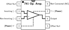
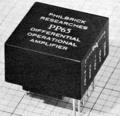
What is an Op-Amp? – The Layout
•There are 8 pins in a common Op-Amp, like the 741 which is used in many instructional courses.
Op-Amp------------------------------------------------------------------------------- Next Slide
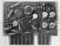
What is an Op-Amp? – The Inside
•The actual count varies, but an Op-Amp contains several Transistors, Resistors, and a few Capacitors and Diodes.
•For simplicity, an Op-Amp is often depicted as this:
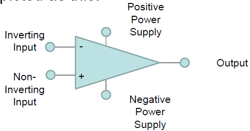
Op-Amp------------------------------------------------------------------------------- Next Slide
History of the Op-Amp – The Dawn
•Before the Op-Amp: Harold S. Black develops the feedback amplifier for the Western Electric Company (1920-1930)
Op-Amp------------------------------------------------------------------------------- Next Slide
History of the Op-Amp – The Dawn
•The Vacuum Tube Age
•The First Op-Amp: (1930 – 1940) Designed by Karl Swartzel for the Bell Labs M9 gun director
•Uses 3 vacuum tubes, only one input, and ± 350 V to attain a gain of 90 dB
•Loebe Julie then develops an Op-Amp with two inputs: Inverting and Non-inverting
Op-Amp------------------------------------------------------------------------------- Next Slide
History of the Op-Amp – The Shift
•The end of Vacuum Tubes was built up during the 1950’s-1960’s to the advent of solid-state electronics
1.The Transistor
2.The Integrated Circuit
3.The Planar Process
Op-Amp------------------------------------------------------------------------------- Next Slide
History of the Op-Amp – The Shift
•1960s: beginning of the Solid State Op-Amp
•Example: GAP/R P45 (1961 – 1971)
–Runs on ± 15 V, but costs $118 for 1 – 4
•The GAP/R PP65 (1962) makes the Op-Amp into a circuit component as a potted module
Op-Amp------------------------------------------------------------------------------- Next Slide
History of the Op-Amp – The Evolution
•The solid-state decade saw a proliferation of Op-Amps
–Model 121, High Speed FET family, etc.
•Robert J. Widlar develops the μA702 Monolithic IC Op-Amp (1963) and shortly after the μA709
•Fairchild Semiconductor vs. National Semiconductor
–National: The LM101 (1967) and then the LM101A (1968) (both by Widlar)
–Fairchild: The “famous” μA741 (by Dave Fullager 1968) and then the μA748 (1969)
Op-Amp------------------------------------------------------------------------------- Next Slide
Mathematics of the Op-Amp
•The gain of the Op-Amp itself is calculated as:
G = Vout/(V+ – V-)
•The maximum output is the power supply voltage
•When used in a circuit, the gain of the circuit (as opposed to the op-amp component) is:
Av = Vout/Vin
Op-Amp------------------------------------------------------------------------------- Next Slide
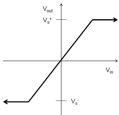
Op-Amp Saturation
•As mentioned earlier, the maximum output value is the supply voltage, positive and negative.
•The gain (G) is the slope between saturation points.
Op-Amp------------------------------------------------------------------------------- Next Slide
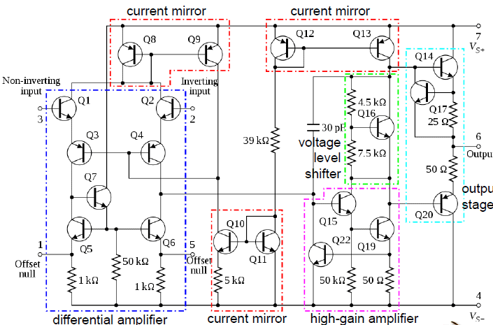
741 Op-Amp Schematic
Op-Amp------------------------------------------------------------------------------- Next Slide
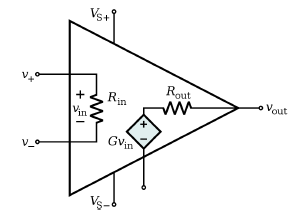
Op-Amp Characteristics
• Open-loop gain G is typically over 9000
• But closed-loop gain is much smaller
• Rin is very large (MΩ or larger)
• Rout is small (75Ω or smaller)
• Effective output impedance in closed loop is very small
Op-Amp------------------------------------------------------------------------------- Next Slide
Ideal Op-Amp Characteristics
• Open-loop gain G is infinite
• Rin is infinite
• Zero input current
• Rout is zero
Op-Amp------------------------------------------------------------------------------- Next Slide
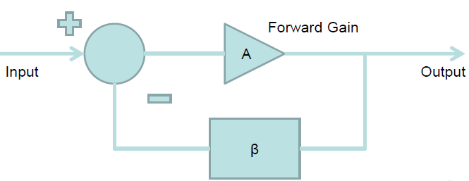
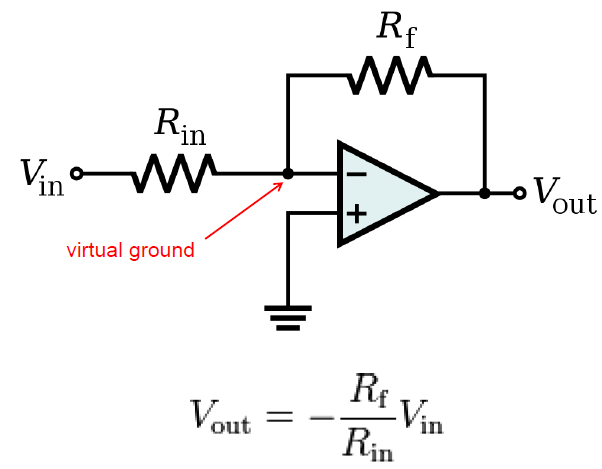
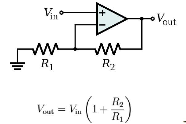
Ideal Op-Amp Analysis
To analyze an op-amp feedback circuit:
• Assume no current flows into either input terminal
• Assume no current flows out of the output terminal
• Constrain: V+ = V-
Op-Amp------------------------------------------------------------------------------- Next Slide
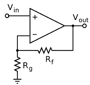
Inverting Amplifier Analysis
Op-Amp------------------------------------------------------------------------------- Next Slide
Non-Inverting Amplifier Analysis
Op-Amp------------------------------------------------------------------------------- Next Slide
Op-Amp Buffer
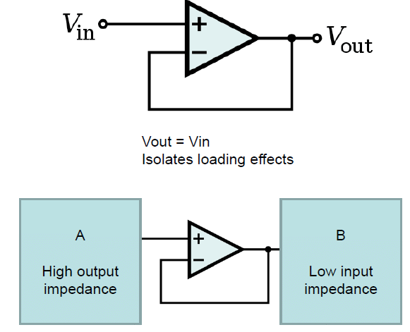
Op-Amp------------------------------------------------------------------------------- Next Slide
Op-Amp Differentiator
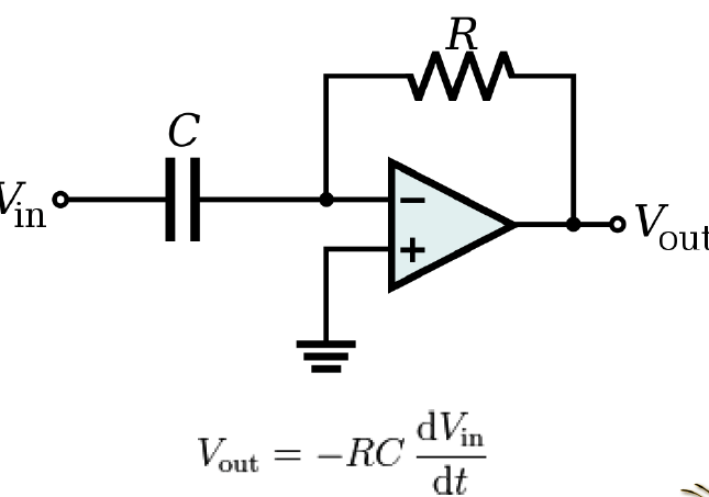
Op-Amp------------------------------------------------------------------------------- Next Slide
Op-Amp Integrator
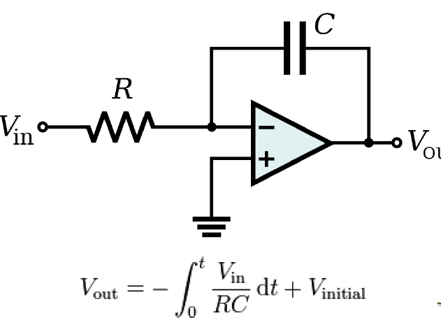
Op-Amp------------------------------------------------------------------------------- Next Slide
Op-Amp Summing Amplifier
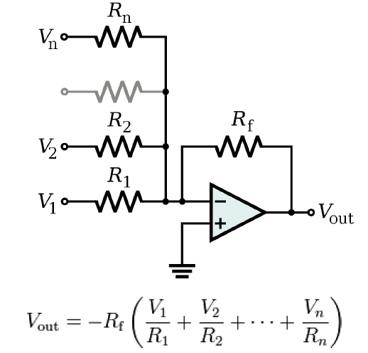
Op-Amp------------------------------------------------------------------------------- Next Slide
Op-Amp Differential Amplifier
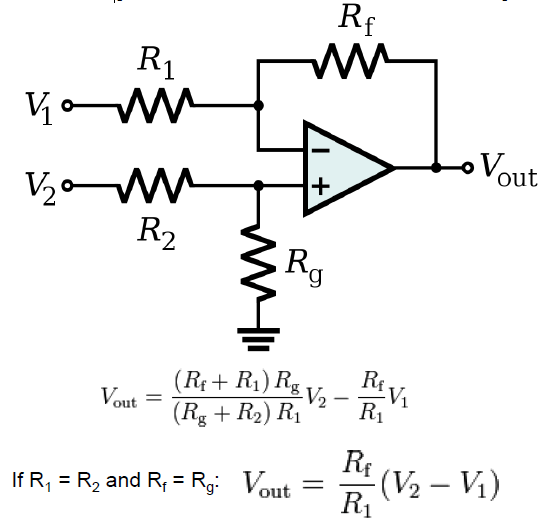
Op-Amp------------------------------------------------------------------------------- Next Slide
Applications of Op-Amps
Filters Types:
•Low pass filter
•High pass filter
•Band pass filter
•Cascading (2 or more filters connected together)
Op-Amp------------------------------------------------------------------------------- Next Slide
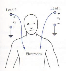
Applications of Op-Amps
•Electrocardiogram (EKG) Amplification
–Need to measure difference in voltage from lead 1 and lead 2
–60 Hz interference from electrical equipment
Op-Amp------------------------------------------------------------------------------- Next Slide
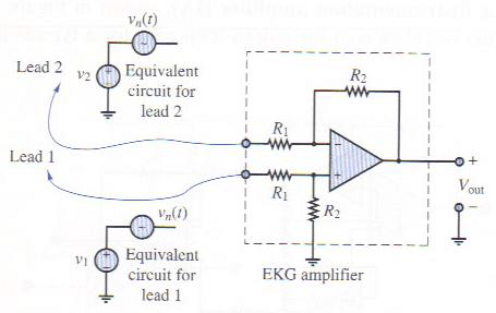
Applications of Op-Amps
•Simple EKG circuit
–Uses differential amplifier to cancel common mode signal and amplify differential mode signal
•Realistic EKG circuit
–Uses two non-inverting amplifiers to first amplify voltage from each lead, followed by differential amplifier
–Forms an “instrumentation amplifier”
Op-Amp------------------------------------------------------------------------------- Next Slide
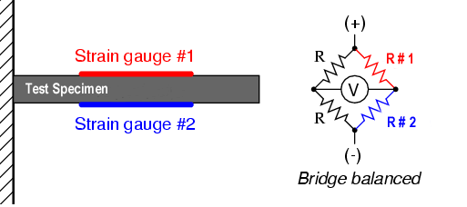
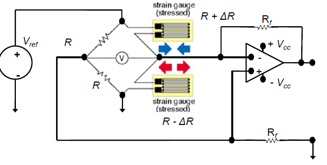
Strain Gauge
Use a Wheatstone bridge to determine the strain of an element by measuring the change in resistance of a strain gauge (No strain) Balanced Bridge R #1 = R #2 (Strain) Unbalanced Bridge
Op-Amp------------------------------------------------------------------------------- Next Slide
Strain Gauge
Half-Bridge Arrangement
Op-Amp------------------------------------------------------------------------------- Next Slide
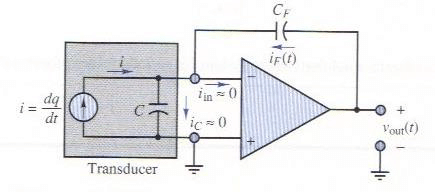
Applications of Op-Amps
•Piezoelectric Transducer
–Used to measure force, pressure, acceleration
–Piezoelectric crystal generates an electric charge in response to deformation
•Use Charge Amplifier
–Just an integrator op-amp circuit
Op-Amp------------------------------------------------------------------------------- Next Slide
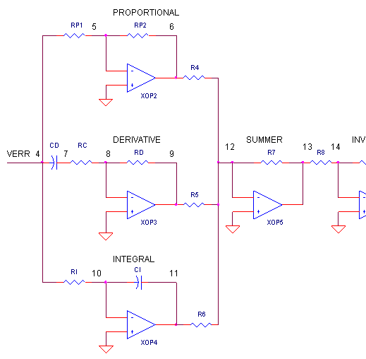
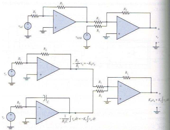
Applications PID Controller – System Circuit Diagram
Op-Amp------------------------------------------------------------------------------- Next Slide
Op-Amp------------------------------------------------------------------------------- Next Slide
Applications of Op-Amps
•Example of PI Control: Temperature Control
•Thermal System we wish to automatically control the temperature of:
•Block Diagram of Control System:
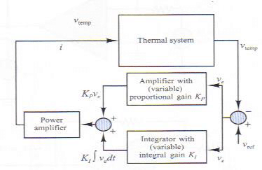
Op-Amp------------------------------------------------------------------------------- Next Slide
Applications of Op-Amps
•Voltage Error Circuit:
•Proportional-Integral Control Circuit:
FAQs on Chapter : What Is An Op-Amp, PPT, Semester, Engineering
| 1. What is an operational amplifier (op-amp) and how does it work? |  |
| 2. What are some common applications of operational amplifiers? | |
| 3. What are the key characteristics or parameters to consider when selecting an operational amplifier? | |
| 4. What is the difference between a single supply and dual supply operational amplifier? | |
| 5. What are some common op-amp circuits that can be implemented in electronics and communication engineering? | |

