ER‐Model


Definition
ER Model is used to model the logical view of the system from data perspective which consists of these components:
Entity, Entity Type, Entity Set
An Entity may be an object with a physical existence - a particular person, car, house, or employee - or it may be an object with a conceptual existence - a company, a job, or a university course.
An Entity is an object of Entity Type and set of all entities is called as entity set. e.g.; E1 is an entity having Entity Type Student and set of all students is called Entity Set. In ER diagram, Entity Type is represented as:

Attribute
Attributes are the properties which define the entity type. For example, Roll_No, Name, DOB, Age, Address, Mobile_No are the attributes which defines entity type Student. In ER diagram, attribute is represented by an oval.
Try yourself: What is an Entity in the ER Model?
Key Attribute
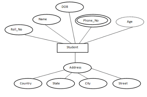
The attribute which uniquely identifies each entity in the entity set is called key attribute.For example, Roll_No will be unique for each student. In ER diagram, key attribute is represented by an oval with underlying lines.

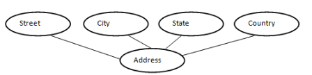
Composite Attribute
An attribute composed of many other attribute is called as composite attribute. For example, Address attribute of student Entity type consists of Street, City, State, and Country. In ER diagram, composite attribute is represented by an oval comprising of ovals.
Multivalued Attribute
An attribute consisting more than one value for a given entity. For example, Phone_No (can be more than one for a given student). In ER diagram, multivalued attribute is represented by double oval.

Derived Attribute
An attribute which can be derived from other attributes of the entity type is known as derived attribute. e.g.; Age (can be derived from DOB). In ER diagram, derived attribute is represented by dashed oval.

The complete entity type Student with its attributes can be represented as:
Relationship Type and Relationship Set
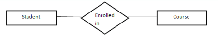
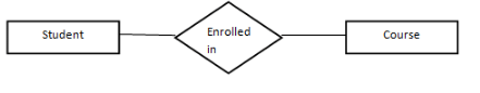
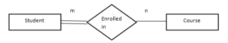
A relationship type represents the association between entity types. For example,'Enrolled in' is a relationship type that exists between entity type Student and Course. In ER diagram, relationship type is represented by a diamond and connecting the entities with lines.
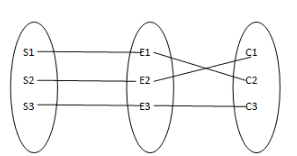
A set of relationships of same type is known as relationship set. The following relationship set depicts S1 is enrolled in C2, S2 is enrolled in C1 and S3 is enrolled in C3.
Degree of a relationship set
The number of different entity sets participating in a relationship set is called as degree of a relationship set.
Unary Relationship
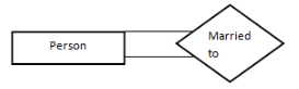
When there is only ONE entity set participating in a relation, the relationship is called as unary relationship. For example, one person is married to only one person.
Binary Relationship
When there are TWO entities set participating in a relation, the relationship is called as binary relationship.For example, Student is enrolled in Course.
n-ary Relationship
When there are n entities set participating in a relation, the relationship is called as n-ary relationship.
Cardinality
The number of times an entity of an entity set participates in a relationship set is known as cardinality. Cardinality can be of different types:
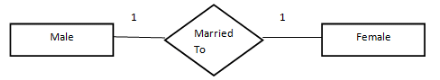
One to One: When each entity in each entity set can take part only once in the relationship, the cardinality is one to one. Let us assume that a male can marry to one female and a female can marry to one male. So the relationship will be one to one.
Using Sets, it can be represented as:
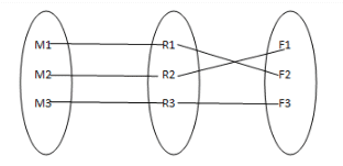
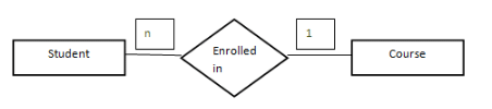
Many to one
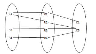
When entities in one entity set can take part only once in the relationship set and entities in other entity set can take part more than once in the relationship set, cardinality is many to one. Let us assume that a student can take only one course but one course can be taken by many students. So the cardinality will be n to 1. It means that for one course there can be n students but for one student, there will be only one course.
Using Sets, it can be represented as:
In this case, each student is taking only 1 course but 1 course has been taken by many students.
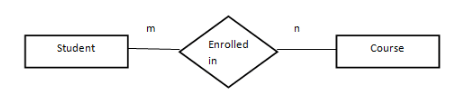
Many to Many
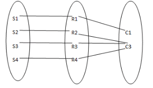
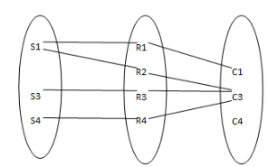
When entities in all entity sets can take part more than once in the relationship cardinality is many to many. Let us assume that a student can take more than one course and one course can be taken by many students. So the relationship will be many to many.
Using sets, it can be represented as:
In this example, student S1 is enrolled in C1 and C3 and Course C3 is enrolled by S1, S3 and S4. So it is many to many relationships.
Participation Constraint
Participation Constraint is applied on the entity participating in the relationship set.
Total Participation: Each entity in the entity set must participate in the relationship. If each student must enroll in a course, the participation of student will be total. Total participation is shown by double line in ER diagram.
Partial Participation: The entity in the entity set may or may NOT participate in the relationship. If some courses are not enrolled by any of the student, the participation of course will be partial.
The diagram depicts the 'Enrolled in' relationship set with Student Entity set having total participation and Course Entity set having partial participation.
Using set, it can be represented as,
Every student in Student Entity set is participating in relationship but there exists a course C4 which is not taking part in the relationship.
Weak Entity Type and Identifying Relationship
As discussed before, an entity type has a key attribute which uniquely identifies each entity in the entity set. But there exists some entity type for which key attribute can't be defined. These are called Weak Entity type.
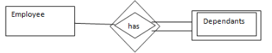
For example, A company may store the information of dependants (Parents, Children, Spouse) of an Employee. But the dependents don't have existence without the employee. So Dependent will be weak entity type and Employee will be Identifying Entity type for Dependant.
A weak entity type is represented by a double rectangle. The participation of weak entity type is always total. The relationship between weak entity type and its identifying strong entity type is called identifying relationship and it is represented by double diamond.
Minimization of ER Diagram
Entity Relationship (ER) Diagram is diagrammatic representation of data in databases, it shows how data is related.
Note: This article for those who already know what is ER diagram and how to draw ER diagram.
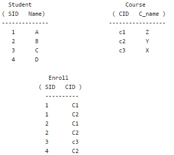
When there is One to Many cardinality in ER diagram
For example, a student can be enrolled only in one course, but a course can be enrolled by many students
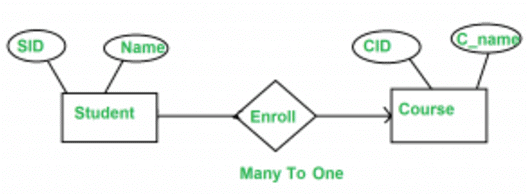
For Student(SID, Name), SID is the primary key. For Course ( CID, C_name ), CID is the primary key
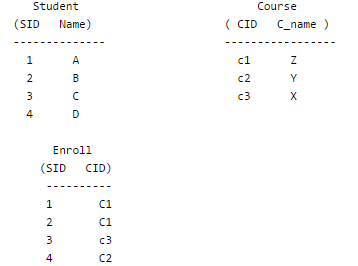
Now the question is, what should be the primary key for Enroll SID or CID or combined. We can't have CID as primary key as you can see in enroll for the same CID we have multiples SID. (SID , CID) can distinguish table uniquely, but it is not minimum. So SID is the primary key for the relation enroll.
For above ER diagram, we considered three tables in database:
Student
Enroll
Course
But we can combine Student and Enroll table renamed as Student_enroll.
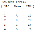
Student and enroll tables are merged now .
So require minimum two DBMS tables for Student_enroll and Course.
Note: In One to Many relationship we can have minimum two tables.
When there is Many to Many cardinality in ER Diagram
Let us consider above example with the change that now student can also enroll more than 1 course.
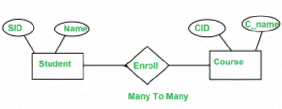
Now, same question what is the primary key of Enroll relation, if we carefully analyse the Enroll primary key for Enroll
table is ( SID , CID ).
But in this case we can't merge Enroll table with any one of Student and Course. If we try to merge Enroll with any one of the Student and Course it will create redundant data.
Note: Minimum three tables are required in Many to Many relationship.
One to One Relationship
There are two possibilities
A. If we have One to One relationship and we have total participation at at-least one end.
For example, consider the below ER diagram.
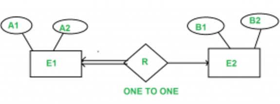
A1 and B1 are primary keys of E1 and E2 respectively.
In the above Diagram we have total participation at E1 end.
For this scenario, either A1 or B1 can be primary key of R.
So, we can merge E1, R, E2 into one table lets say E1RE2 .
Note: Minimum 1 table is required.
B. One to One relationship with no total participation.
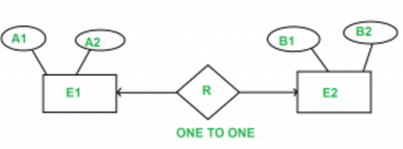
A1 and B1 are primary keys of E1 and E2 respectively.
Primary key of R can be A1 or B1, but we can't still combine all the three table into one. if we do, so some entries in combined table may have NULL entries. So idea of merging all three table into one is not good.
But we can merge R into E1 or E2. So minimum 2 tables are required.
Mapping from ER Model to Relational Model
After designing the ER diagram of system, we need to convert it to Relational models which can directly be implemented by any RDBMS like Oracle, MySQL etc. In this article we will discuss how to convert ER diagram to Relational Model for different scenarios.
Case 1. Binary Relationship with 1:1 cardinality with total participation of an entity
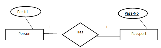
A person has 0 or 1 passport number and Passport is always owned by 1 person. So it is 1:1 cardinality with full participation constraint from Passport.
First Convert each entity and relationship to tables. Person table corresponds to Person Entity with key as Per-Id. Similarly Passport table corresponds to Passport Entity with key as Pass-No. Has Table represents relationship between Person and Passport (Which person has which passport). So it will take attribute Per-Id from Person and Pass-No from Passport.
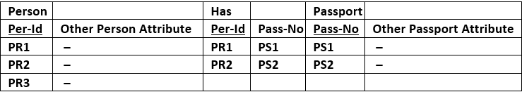
As we can see from Table 1, each Per-Id and Pass-No has only one entry in Has table. So we can merge all three tables into 1 with attributes shown in Table 2. Each Per-Id will be unique and not null. So it will be the key. Pass-No can't be key because for some person, it can be NULL.
Case 2: Binary Relationship with 1:1 cardinality and partial participation of both entities
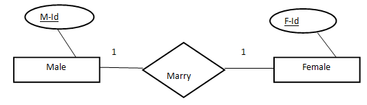
A male marries 0 or 1 female and vice versa as well. So it is 1:1 cardinality with partial participation constraint from both. First Convert each entity and relationship to tables. Male table corresponds to Male Entity with key as M-Id. Similarly Female table corresponds to Female Entity with key as F-Id. Marry Table represents relationship between Male and Female (Which Male marries which female). So it will take attribute M-Id from Male and F-Id from Female.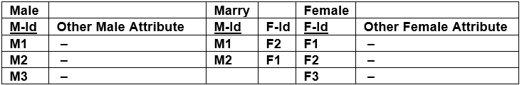 Table 3 As we can see from Table 3, some males and some females do not marry. If we merge 3 tables into 1, for some M-Id, F-Id will be NULL and for some F-Id, M-Id will be NULL. So there is no attribute which is always not NULL. So we can't merge all three tables into 1. We can convert into 2 tables. In table 4, M-Id who are married will have F-Id associated. For others, it will be NULL. Table 5 will have information of all females. Primary Keys have been underlined.
| M-Id | Other Male Attribute | F-Id |
Table 4
| F-Id | Other FemaleAttribute |
Table 5
Note: Binary relationship with 1:1 cardinality will have 2 table if partial participation of both entities in the relationship. If atleast 1 entity has total participation, number of tables required will be 1.
Case 3: Binary Relationship with n: 1 cardinality
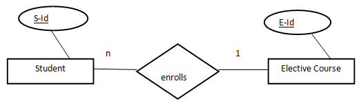
In this scenario, every student can enroll only in one elective course but for an elective course there can be more than one student. First Convert each entity and relationship to tables. Student table corresponds to Student Entity with key as S-Id. Similarly Elective_Course table corresponds to Elective_Course Entity with key as E-Id. Enrolls Table represents relationship between Student and Elective_Course (Which student enrolls in which course). So it will take attribute S-Id from Person and E-Id from Passport.
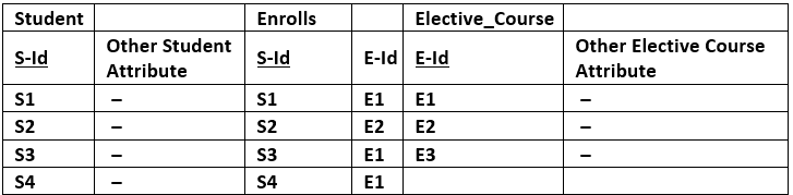
| S-Id | Other Student Attribute | E-Id |
Table 7
| E-Id | Other Elective Course Attribute |
Table 8
Try yourself: What is the primary key of the Enroll relation in an ER diagram when there is a many-to-many cardinality?
Case 4: Binary Relationship with m: n cardinality
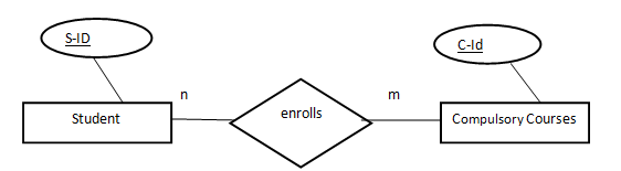
In this scenario, every student can enroll in more than 1 compulsory course and for a compulsory course there can be more than 1 student. First Convert each entity and relationship to tables. Student table corresponds to Student Entity with key as S-Id. Similarly Compulsory_Courses table corresponds to Compulsory Courses Entity with key as C-Id. Enrolls Table represents relationship between Student and Compulsory_Courses (Which student enrolls in which course). So it will take attribute S-Id from Person and C-Id from Compulsory_Courses.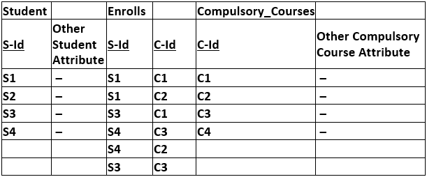
As we can see from Table 9, S-Id and C-Id both are repeating in Enrolls Table. But its combination is unique; so it can be considered as a key of Enrolls table. All tables' keys are different, these can't be merged. Primary Keys of all tables have been underlined.
Case 5: Binary Relationship with weak entity
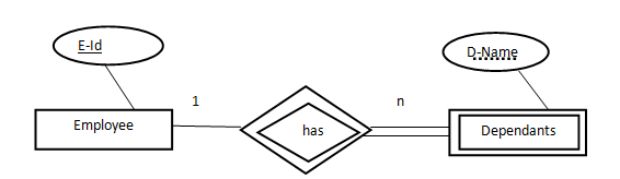
In this scenario, an employee can have many dependants and one dependant can depend on one employee. A dependant does not have any existence without an employee (e.g; you as a child can be dependant of your father in his company). So it will be a weak entity and its participation will always be total. Weak Entity does not have key of its own. So its key will be combination of key of its identifying entity (E-Id of Employee in this case) and its partial key (D-Name).
First Convert each entity and relationship to tables. Employee table corresponds to Employee Entity with key as E-Id. Similarly Dependants table corresponds to Dependant Entity with key as D-Name and E-Id. Has Table represents relationship between Employee and Dependants (Which employee has which dependants). So it will take attribute E-Id from Employee and D-Name from Dependants.
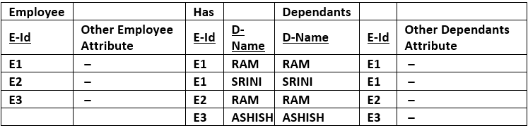
As we can see from Table 10, E-Id, D-Name is key for Has as well as Dependants Table. So we can merge these two into 1. So the resultant tables are shown in Tables 11 and 12. Primary Keys of all tables have been underlined.
| E-Id | Other Employee Attribute |
Table 11
| D-Name | E-Id | Other DependantsAttribute |
Table 12
FAQs on ER‐Model
| 1. What exactly is an entity in the ER model and how is it different from an attribute? |  |
| 2. Why do we need to use relationships in ER models instead of just storing all data in one table? | |
| 3. How do cardinality and participation constraints affect database design in the ER model? | |
| 4. Can an attribute in an ER diagram be something other than a simple single value? | |
| 5. What's the practical difference between a weak entity and a strong entity when designing databases? | |


 | Explore Courses for Computer Science Engineering (CSE) exam |
 | Get EduRev Notes directly in your Google search |