Variable Stresses in Machine Parts

VARIABLE STRESSES IN MACHINE PARTS
- The stresses which vary from a minimum value to a maximum value of the same nature (i.e. tensile or compressive) are called fluctuating stresses.
- The stresses which vary from one value of compressive to the same value of tensile or vice versa, are known as completely reversed or cyclic stresses.
- The stresses which vary from a minimum value to a maximum value of the opposite nature (i.e. from a certain minimum compressive to a certain maximum tensile or from a minimum tensile to a maximum compressive) are called alternative stresses.
- When a material is subjected to repeated stresses, it fails at stresses below the yield point stresses. Such type of failure of a material is known as fatigue. The failure may occur even without any prior indications. The fatigue of material is effected by the size of the component, relative magnitude of static and fluctuating loads and the number of load reversals.
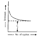
- If the stress is kept below a certain value as shown by dotted line, the material will not fail whatever may be the number of cycles. This stress, as represented by dotted line, is known as endurance or fatigue limit (fe). It is defined as maximum value of the completely reversed bending stress which a polished standard specimen can withstand without failure, for infinite number of cycles (usually 106 cycles).
- The term endurance limit is used for reversed bending only while for other types of loading, the term endurance strength may be used when referring the fatigue strength of the material.
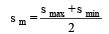
- Mean or average stress :
- Reversed stress component or variable stress :

- For repeated loading (smin = 0),

- Effect of loading on Endurance Limit
- The endurance limit will be different for different types of loading.
Kb = Loads correction factor for reversed bending load. Its value is usually taken as unity.
Ka = Load correction factor for the reversed axial load. Its value may be taken as 0.8.
Ks = Load correction factor for the reversed torsional or shear load. Its value may be taken as 0.55.
Ksur = surface finish factor.
Ksz = Size factor, this is due to the fact that a longer specimen will have more defects than a smaller one.
Kr = reliability factor.
Kt = temperature factor.
Ki = Impact factor.
- For reversed bending load, endurance limit :
f1e = feb .Ksur .K sz .K r .K t .K i
- For the reversed axial load, endurance limit : 1
f1e = f ea .K sur .Ksz .Kr .K t .Ki
- For the reversed torsional or shear load, endurance limit :
f1e = f es .Ksur .Ksz .K r .K t .K i
- In solving problems, if the value of any of the above factors is not known; it may be taken as unity.
- The factor of safety for fatigue loading should be based on endurance limit.
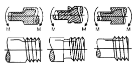
Stress Concentration
- When a machine component changes the shape of its cross-section, the simple stress distribution no longer holds good and neighborhood of the discontinuity is different. This irregularity in the stress distribution caused by abrupt changes in the shape is called stress concentration.
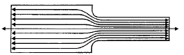
The material near the edges is stressed considerably higher than the average value. The maximum stress occurs at some point on the fillet and is directed parallel to the boundary at that point.
- Theoretical or form stress concentration factor is defined as the ratio of the maximum stress in a member (at a notch or a fillet) to the nominal stress at the same section. It is denoted by Kt.
- In static loading, stress concentration in ductile material is not so serious as in brittle materials, because in ductile materials local deformation or yielding takes place which reduces the concentration. In brittle materials, cracks may appear at these local concentration of stress which will increases the stress over the rest of the section. In order to avoid failure due to stress concentration, fillets at the changes of section must be provided.
- In cyclic loading, stress concentration is always serious because the ductility of the material is not effective in relieving the concentration of stress caused by cracks, flaws or any sharp discontinuity in the geometrical form of the member.
If the stress at any point in a member is above the endurance limit of the material, a crack may develop under the section of repeated load and the crack will lead to failure of the member.
Stress concentration due to holes
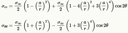
σrr is the radial stress
σθθ is the tangential stress
- The maximum stress occurs at the edge of the hole.
- The stress at the joints away from the hole is practically uniform and the maximum stress will be induced at the edge of the hole.
- The presence of stress concentration can not be totally eliminated but it may be reduced to some extent.
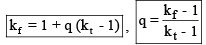
Notch Sensitivity
- It may be defined as the degree to which theoretical effect of stress concentration is actually reached. The stress gradient depends mainly on the radius of notch, hole or fillet and on the grain size of material. When notch sensitivity factor q is used in cyclic loading, then fatigue stress concentration factor may be obtained by the relations :
- There are several ways in which problems involving combination of stresses may be solved.
Gerber Method
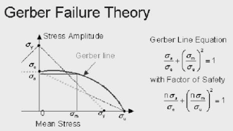
- The Gerber Failure Theory differs from the Soderberg and the Goodman theories in that it represents the failure line as a quadratic curve that passes through the endurance limit and the tensile stress. Of the three theories it is the least conservative and is considered by many to be the more accurate of the true behavior and impact of fluctuating loads on fatigue strength. Analytically it is represented by the equation the ratio of the alternate stress, sigma a, to the endurance limit, sigma e, plus the square of the ratio of the mean stress, sigma m, to the tensile strength, sigma u, is equal to one. To introduce a factor of safety into this express n is added to the numerator of the two stress ratios on the left side of the equation. Of the three theories presented preference for design applications and analysis is generally accorded to the Goodman theory.
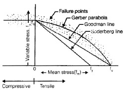
Goodman Method for Combination of Stresses
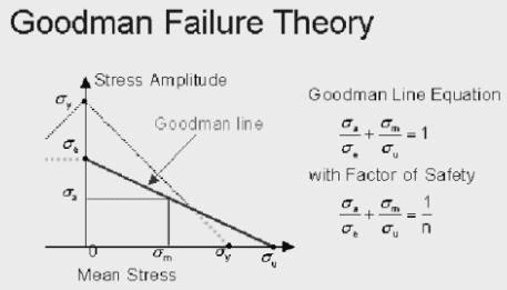
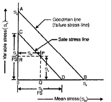
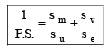
- The second proposed failure theory for fatigue design application under a general fluctuating normal stress loading is the Goodman Theory. It proposes a failure line that extends from the endurance limit on the vertical axis to the tensile strength on the horizontal axis. In effect it discounts yielding as a failure condition and is less conservative than the Soderberg theory particularly for mean stress values in excess of the yield strength. Analytically it is defined by the equation that the ratio of the alternating stress, sigma a, to the endurance limit, sigma e, plus the ratio of the mean stress, sigma m, to the tensile stress, sigma u, is equal to one. Again a factor of safety, n, can be introduced by dividing the right side of the equation by n.
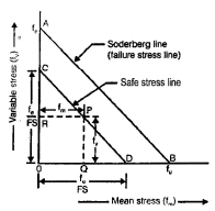
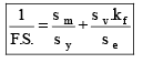
Soderberg Method
- A straight line connecting the endurance limit (fe) and the yield strength (fy) is a Soderberg line. This line is used when the design is based on yield strength.
If a suitable factor of safety (F.S.) is applied to the endurance limit and yield strength, a safe stress line CD may be drawn parallel to the line AB.
FAQs on Variable Stresses in Machine Parts
| 1. What are variable stresses in machine parts? |  |
| 2. How do variable stresses affect the performance and lifespan of machine parts? | |
| 3. What are some common methods used to analyze variable stresses in machine parts? | |
| 4. How can variable stresses be reduced or mitigated in machine parts? | |
| 5. What are some practical examples where variable stresses are encountered in mechanical engineering? | |


