Welded Joints | Mechanical Engineering SSC JE (Technical) PDF Download
WELDED JOINTS
- A welded joint is a permanent joint which is obtained by the fusion of the edges of the two parts to be joined together, with or without the application of pressure and a filler material.
Advantages of welding Joints
- The welded structure are usually lighter than riveted structures.
- The welded joints provide maximum efficiency (may be 100%) which is not possible in case of riveted joints.
- Alterations and addition can be easily made in existing structure.
- In welding connections, the tension members are not weakened as in case of riveted joints.
- A welded joint has a great strength. Often a welded joint has the strength of the parent metal itself.
- The welding provides very rigid joints.
- The process of welding takes less time than the riveting.
Disadvantages
- Since there is an uneven heating and cooling during fabrication, therefore the members may get distorted or additional stresses may develop.
- It requires a highly skilled labour and supervision.
- Since no provision is kept for expansion and contraction in the frame, therefore there is a possibility of cracks developing in it.
- The inspection of welding work is more difficult than riveting work.
What is welding, and why is it done?
- Welding is a time-tested fabrication process or sculpting process of materials, usually metal, using high temperatures to melt and fuse parts together. It should be noted that, however, pressure can also be used to aid the process or be used exclusively to produce a weld.
- "The process of welding doesn't merely bond the two pieces together as in brazing and soldering, but, through the use of extreme heat and sometimes the addition of other metals or gases, causes the metallic structures of the two pieces to join together and become one." - brighthubengineering.com.
- It is usually distinguished from lower temperature metal fusing techniques like brazing, or soldering, which do not usually melt the base metal.
- Welding usually also involves the use of something called a filler material. This, as the name suggests, is used to provide a "filler" or pool of molten material that helps facilitate the formation of a strong link between the base metal parts.
Types of Welding
- MIG - Gas Metal Arc Welding (GMAW)
- This welding process uses a continuously fed electrode through a welding gun and the operator needs to pull a trigger in order to feed the consumable electrode through. Between the base material and the electrode an electric arc forms, which heats the material until it reaches the melting point that makes it possible to get it joined with another.
- TIG - Gas Tungsten Arc Welding (GTAW)
- Also known as Heliarc welding, TIG is a welding process that uses a tungsten electrode that is not consumable to heed the base metal and create a molten puddle for the by using this method, you can create are no filler metal or autogenous weld in order to melt two pieces of metal together. You can also add an external filler rod into the molten puddle in order to be able to create a weld bead and increase the mechanical properties of the metal.
- Stick - Shielded Metal Arc Welding (SMAW)
- Commonly referred to as Stick, the shielded metal arc welding is a process that uses an electrode to carry electric current in order to be able to provide most of the weld metal. The electrode used for this method consists of a core wire that is coded influx and the electric arc is created when the tip of the electrode that is the work piece and is withdrawn while still remaining in close contact in order to generate temperatures of about 6500°F.
- Flux-Cored Arc Welding (FCAW)
- This technique is rather similar to the MIG welding method, as it also requires an uninterruptedly fed electrode, but instead of a solid wire, it needs a tube-shaped wire full with flux. You can choose from two types of flux core wire, which are socially and will shield wires. social good wires are a good solution for outdoor use, as they work even in windy situations. n the other hand, double shield uses an external shielding gas and the flux in order to guard the modern weld puddle.
- Electron Beam Welding (EBW)
- This type of welding involves firing a ray of high velocity electrons at the materials that require welding. This technique transforms energy from the electrons into sheets in order to melt the welding materials, which can then merge and fuse together. This type of welding is used in multiple industries, with applications ranging from fully automated automotive inline part production to high-cost aircraft engine industry. Some examples of products that are created with electron beam welding include aerospace components, transmission assemblies, and bimetal saw blades.
- Atomic Hydrogen Welding (AHW)
- This welding technique has been largely replaced by the gas metal arc welding methods, but it is still in use for specific purposes such as welding tungsten. This material is highly resistant to heat and by using this technique, you can weld it in a way that does not damage the metal while still creating cohesive, strong weld. As in all welding jobs it is extremely important to wear welder gloves for protection and safety.
- Gas Tungsten-Arc Welding
- This is one of the most difficult types of welding, and also the most time-consuming, because it requires a lot of focus and skill mostly because of the small area between the art of the flame in the material you intend to weld. For this method small strips of metal are welded with this process in order to obtain an extremely strong weld that is bound to last for years. This welding method has been released in 1941 and it has changed very little since. It is still used by manufacturers of bicycles and aircraft, both military and commercial.
- Plasma Arc Welding
- A process that is similar to that of the gas tungsten arc welding, the plasma arc welding was initially developed in 1954 and it uses electrical current that is passed through a very small nozzle that goes through the protective gases in order to enable extreme accuracy when it comes to welding small areas. This method is a suitable one to use when it comes to heating metal very extreme temperatures which results in deeper and stronger welds. This welding method is often used in the aircraft manufacturing industry, and it is very rare for it to be useful for DIY and enthusiast welders.
The 6 Different Types Of Welding Joints:
Different jobs need different types of welds. Different types of welding joints are made to stand up to the needs and forces of each individual application. The experts at Cliff’s Welding have been mastering the art of these welds for over 50 years. With professionals that have a wide variety of experience there really is not job too big or too small. Let’s go over the 6 types of weld joints that we use to get the job done right.
- Tee Welding Joint

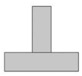
- Tee Joint
Tee welding joints are formed when two members intersect at a 90° angle which makes the edges come together in the center of a plate or component. Tee Joints are considered a type of fillet weld, and can also be made when a pipe or tube is welded onto a base plate. Extra care is required to ensure effective penetration into the roof of the weld. - Lap Welding Joint

- Lap Joint
Lap welding joints are used most often to joint two pieces with differing thicknesses together. Also considered a fillet type, the weld can be made on one or both sides. A Lap Joint is formed when 2 pieces are placed in an over lapping pattern on top of each other. - Edge Welding Joint

- Edge Joint
Edge welding Joints are often applied to sheet metal parts that have flanging edges or are placed at a location where a weld must be made to attach to adjacent pieces. Being a groove type weld, Edge Joints, the pieces are set side by side and welded on the same edge. For heavier applications filler metal is added to melt or fuse the edge completely and to reinforce the plate. - Corner Welding Joint

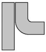
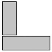
- Corner Joint
Being one of the most popular welds in the sheet metal industry the Corner welding joint is used on the outer edge of the piece. This weld is a type of joint that comes together at right angles between two metal parts to form an L. These are common in the construction of boxes, box frames and similar fabrications. - Butt Welding Joint

- Butt Joint
Being the universally accepted method for attaching a pipe to itself it’s also used for valves, flanges, fittings, and other equipment. A butt welding joint is also known as a square grove weld. It’s the easiest and probably the most common weld there is. It consists of two flat pieces that are side by side parallel. It’s a very affordable option. - Fillet Welding Joint
- Fillet Welded Joints
Fillet Welded Joints are just another terminology for corner, lap, and tee joints. Fillet Welded Joints are the most common type of welding joint and accounts for nearly 75% of joints made with arc welding. You do not need to prepare the edge and this type of joint make it easy to weld piping systems. Butt welds are more expensive than fillet welds. Fillet welds are mostly used in piping systems to join pipe to socket joints.
Elements of a Welding Symbol
- Reference line
- Arrow
- Basic weld symbols
- Dimensions and other data
- Supplementary symbols
- Finish symbols
- Tail
- Specification,
- Process or other references
Strength of Transverse Fillet Welded Joints
- The transverse fillet welds are designed for tensile strength. The length of each side is known as leg or size of the weld and the perpendicular distance of the hypotenuse from the intersection of legs is known as throat thickness. The minimum area of the weld is obtained at the throat , which is given by the product of throat thickness and length of weld.

Let, t = Throat thickness
s = Leg or size of weld = thickness of plate
l = length of weld t = s × sin 45 = 0.707 s.
If st is the allowable tensile stress, then the tensile strength of the joint
- For single fillet weld, P = 0.707 s.l.st
- For double fillet weld, P = 2 × 0.707 s.l.st
- Since the weld is weaker than the plate due to slag and blow holes, therefore the weld is given as reinforcement which may be taken as 10% of the plate thickness.
Strength of Parallel Fillet Welded Joints
- The parallel fillet welded joints are designed for the shear strength.

Minimum area of weld or the throat area
A = 0.707 s.l.
If ts is the allowable stress for the weld meal, then the shear strength of the joint for single parallel fillet weld, P = 0.707 s.l.ts
P = 2 × 0.707 s.l.ts
= 1.414 s.l.ts
- If there is a combination of single transverse and double parallel fillet welds, then the strength of the joint is given by the sum of strengths of single transverse and double parallel fillet welds is P = 0.707 s.l1. st + 1.414. s.l2.ts

- In order to allow for starting and stopping of the bead 12.5 mm should be added to the length of each weld obtained by the above expression.
- For reinforced fillet welds, the throat dimension may be taken s 0.85t.
- The minimum area of the weld is taken because the stress is maximum at minimum area.
Special cases of fillet welded joints
- Circular fillet weld subjected to torsion

Let, d = diameter of rod
r = Radius of rod
T = Torque acting on the rod
S = size of weld
t = throat thickness
J = Polar moment of inertia of the weld section.
Shear stress for the material

- The maximum shear stress occurs on the throat of weld which is inclined at 45° to the horizontal plane.

Strength of Butt Joints
- The butt joints are designed for tension or compression. In case of butt joint, the length of leg or size of weld is equal to the throat thickness which is equal to thickness of plates.

Tensile strength of the butt joint P = t.l.st (for single butt joint) where, l = length of weld, It is generally equal to the width of plate. - For static loading and any type of joint, stress concentration factor is 1.0.
|
5 videos|103 docs|59 tests
|
FAQs on Welded Joints - Mechanical Engineering SSC JE (Technical)
| 1. What is a welded joint in mechanical engineering? |  |
| 2. What are the advantages of using welded joints in mechanical engineering? |  |
| 3. What are the different types of welded joints commonly used in mechanical engineering? |  |
| 4. What factors should be considered when designing a welded joint in mechanical engineering? |  |
| 5. What are some common defects that can occur in welded joints in mechanical engineering? |  |
|
5 videos|103 docs|59 tests
|

|
Explore Courses for Mechanical Engineering exam
|

|


