Mechanical Engineering Exam > Mechanical Engineering Notes > SSC JE (Technical) > Supercharging, Engine Testing & Emissions
Supercharging, Engine Testing & Emissions


Supercharging: purpose and basic idea
- To increase the power output of an internal combustion engine one or more of the following may be done:
- Increase the mass of air inducted per unit time so that more fuel can be burned.
- Improve the degree of utilisation of the inducted air.
- Improve the thermal efficiency of the cycle.
- To increase the air inducted per unit time, either the engine speed or the intake air density must be raised.
- Supercharging is the increase of intake air density above atmospheric value so that a larger mass of air is inducted in a given swept volume.
- Supercharging also compensates for reduced air density at high altitude and so is important for aircraft engines.
- Supercharging increases the tendency for detonation (knock) in spark-ignition (SI) engines; therefore the practical limit of supercharging for SI engines is set by detonation and available cooling. SI supercharging is most often used in aircraft and racing applications where higher power per unit mass is required.
- For compression-ignition (CI) engines supercharging generally lowers the tendency to detonation and is therefore widely used; benefits include higher power, better economy and lower smoke if properly tuned. The limit for supercharging of CI engines is usually governed by thermal loading and peak temperatures.
Effect of supercharging on engine performance
- Increased power output from the same engine displacement.
- Small improvement in mechanical efficiency due to higher torque at the same friction losses.
- Improved scavenging in two-stroke or poorly scavenged four-stroke engines and reduced exhaust gas temperatures in some cases.
- Lower specific fuel consumption (better brake specific fuel consumption) when the engine is optimally tuned.
- At part loads, fuel consumption after supercharging can be higher than natural-aspirated engines because of throttling losses, pumping losses and higher heat rejection unless variable or bypass arrangements are used.
Types of compressors used for supercharging
- Mechanically driven superchargers - These are positive-displacement or dynamic compressors driven from the engine crankshaft via belts or gears; examples include Roots, twin-screw and some centrifugal superchargers.
- Turbochargers - The compressor is driven by a turbine powered by exhaust gases. Because the energy comes from exhaust, turbochargers recover waste energy and do not directly take power from the crankshaft (though they impose back-pressure and pumping losses).
- Special forms - Examples include free-piston compressor arrangements or systems where the engine drives the compressor and exhaust gases drive a turbine to obtain shaft power; these configurations are less common but used in some research or specialised engines.
Common supercharger types (brief)
- Roots-type - Positive displacement, gives good low-speed boost, simple and robust but less efficient than screw type.
- Twin-screw (Lysholm) - Positive displacement with higher efficiency and temperature control than Roots for the same boost.
- Centrifugal - Dynamic compressor; efficient at high speeds and often used with turbochargers or belt-driven superchargers in automotive applications.
Turbochargers - additional notes
- Turbochargers combine a turbine (driven by exhaust) and a centrifugal compressor (for the intake air) on a common shaft.
- They are extensively used for CI engines, especially in commercial and heavy-duty engines, because they recover part of the exhaust energy and increase the engine's effective air charge.
- Common practical features: wastegate to limit maximum boost, intercooler to reduce compressed-air temperature, and consideration of turbo lag (delay in boost build-up at low engine speeds).
Basic Performance Parameters of an IC Engine
- Power output - Indicated and brake power; brake power is the useful output available at the crank or output shaft.
- Mechanical efficiency - Ratio of brake power to indicated power; indicates mechanical losses.
- Brake mean effective pressure (BMEP) - Mean pressure that, if acted on the piston crown during the power stroke, would produce the brake torque; useful for comparing engines of different sizes.
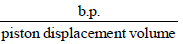
- Specific power output - Power per unit swept volume or per unit mass; useful to compare engines of different displacements.
- Volumetric efficiency - A measure of how fully the engine fills its swept volume with fresh charge relative to the theoretical swept volume.
- Fuel-air ratio - Mass of fuel to mass of air; important for performance, economy and emissions.
- Specific fuel consumption - Fuel consumed per unit power and per unit time (e.g. brake specific fuel consumption, bsfc).
- Thermal efficiency - Ratio of useful work (indicated or brake) to the heat energy available in the fuel.
- Heat balance - Breakdown of input energy into work and various losses (cooling, exhaust, unaccounted).
- Exhaust emissions - Quantities and types of pollutants emitted by the engine.
- Higher mean effective pressure for a given displacement indicates higher power potential; hence mean effective pressure is a true indicator of relative engine performance.
Specific power output =
- Volumetric efficiency indicates the degree of utilisation of the swept volume of the engine.
- For a supercharged engine volumetric efficiency may exceed unity (greater than 100%), so the plain volumetric efficiency concept must be adjusted when forced induction is present.
Alternative form of specific power output =
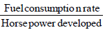
Brake specific fuel consumption (bsfc) =

Indicated specific fuel consumption (isfc) =

- Brake thermal efficiency expresses how effectively the fuel energy is converted to brake power.

Measurement of engine parameters (common methods)
| Parameter | Method of measurement |
|---|---|
| Speed | Tachometer (optical or electronic) |
| Air consumption | Air-box method (measuring mass flow through the intake), or mass-flow sensors |
| Exhaust emission | Flame ionisation detector (FID) for hydrocarbons, infrared or nondispersive infrared analysers for CO/CO₂, chemiluminescence for NOx, spectroscopic analysis where applicable |
| Brake power | Dynamometer (electrical, hydraulic, eddy-current or water-brake) |
| Friction power | Morse test, motoring test, Willan's line method |
Heat balance
- The heat balance is the breakup of total energy input from fuel into various useful and loss heads. Typical heads included are:
- Heat equivalent to the effective work of the engine (useful work).
- Heat rejected to the cooling medium (cooling system losses).
- Heat carried away by exhaust gases.
- Unaccounted heat (radiation, incomplete combustion, measurement errors).
- Frictional losses are usually accounted for separately and are commonly included in mechanical losses or treated as heat rejected via cooling.
Emissions from IC engines
- Air pollution is the addition to the atmosphere of substances harmful to life, health, materials or the environment.
- Main pollutants from road vehicles are:
- Carbon monoxide (CO)
- Unburned hydrocarbons (UBHC or HC)
- Oxides of nitrogen (NOx)
- Particulate matter (soot) especially from diesel engines
- Perfect combustion produces mainly carbon dioxide (CO₂) and water vapour; pollutants arise from incomplete combustion, high peak temperatures, or fuel/air mixture imbalances.
Pollutants from petrol (SI) engines - sources and quantities
| Source | Approximate contribution to HC |
|---|---|
| Evaporative losses from fuel tank and carburettor (vapour) | 15%-25% of total HC |
| Crankcase blow-by fumes | 20%-35% of total HC |
| Exhaust emissions | 50%-60% of HC (plus CO and NOx from combustion) |
- Ketones and aldehydes in exhaust participate in photochemical reactions that form smog in the presence of sunlight.
Carbon monoxide (CO)
- CO emissions generally decrease with increasing vehicle speed.
- CO emissions are high during idling and are maximum during deceleration phases where the mixture is rich and combustion incomplete.
- CO is lowest during steady, well-controlled acceleration with near-stoichiometric mixtures and proper combustion.
Unburned hydrocarbons (HC)
- HC emissions are higher during deceleration, idling and low-speed operation due to incomplete combustion and crevice/quench-area losses.
- Lower surface-to-volume ratio in the combustion chamber reduces HC emission from quench areas. Surface-to-volume can be influenced by compression ratio, stroke-to-bore ratio and combustion-chamber shape.
Oxides of nitrogen (NOx)
- High temperature and availability of oxygen are the main reasons for NOx formation in engines.
- Both very lean and very rich mixtures produce lower NOx; near-stoichiometric mixtures with high peak temperatures tend to produce the most NOx.
- Advancing spark timing increases peak temperatures and hence increases NOx concentration in the exhaust.
- The combination of HC and NOx in sunlight contributes to photochemical smog.
Control of air pollution from petrol engines
- Use a leaner air-fuel ratio where feasible to reduce CO and HC (note trade-offs with NOx).
- Retard ignition timing to reduce peak temperatures and NOx (but this may increase HC and fuel consumption).
- Reduce quench areas in the combustion chamber to lower UBHC emissions (combustion-chamber design changes).
- Lower the compression ratio where required to reduce peak temperatures and NOx.
- Reduce valve overlap to limit escape of UBHC into exhaust during valve events.
- Afterburning of exhaust gases by supplying oxygen (secondary air injection) and/or by using thermal reactors.
- Recirculate crankcase blow-by gases back to the intake (via air cleaner) to prevent evaporative HC losses to atmosphere.
Total emission control package (thermal reactor)
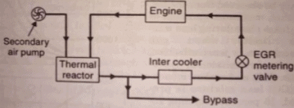
- A thermal reactor is an enlarged manifold or chamber in the exhaust stream that increases residence time and temperature so that HC and CO remaining in exhaust can oxidise to CO₂ and H₂O in the presence of pumped-in air. Some systems recirculate a portion (typically about 10%-15%) of exhaust gas back to the intake via an intercooler or cooler to reduce combustion temperature and control NOx.
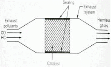
Catalytic converter package
- Catalytic converters are arranged so that a NOx catalyst is first in the exhaust path (to reduce NOx), followed by an oxidation catalyst for HC and CO. The catalysts facilitate chemical reactions without themselves being consumed. Converter systems can cause heat release where oxidation takes place.
- Catalytic converters require unleaded petrol because leaded fuel poisons the catalyst surface and degrades performance.
- Use of catalytic converters may alter engine tuning; historically, early converter systems were associated with some loss of power (reported as up to ~30% in some early heavy systems) and modest increases in fuel consumption (figures vary by system and vehicle design). Modern systems are far more efficient with minimal power or fuel penalties.
Diesel (CI) engine emissions
- Turbocharged diesel engines normally show low HC but can have higher NOx, depending on load and injection timing.
- At idle, HC and NOx concentrations are generally low but soot/particulate can still be present if combustion is incomplete.
- Acceleration and high-load operation increase smoke (particulate) levels because of temporary rich local mixtures and incomplete mixing/combustion.
- Maximum emission of particulates and NOx tends to occur near full load or during aggressive acceleration.
- Precombustion chamber designs or indirect injection designs can reduce NOx but often trade off with slightly higher particulates or fuel consumption.
Causes of smoke (diesel)
- Incomplete combustion.
- Incorrect air-fuel ratio (rich local mixtures).
- Poor mixing of fuel and air.
- Poor atomisation of fuel or excessive injection duration.
Emission control - summary of measures
- For SI engines: mixture control (lean burn where possible), improved combustion-chamber design to reduce quench areas, optimised ignition timing, evaporative control (charcoal canisters), secondary air injection, catalytic converters and thermal reactors.
- For CI engines: optimisation of injection timing and spray, turbocharging with intercooling, exhaust gas recirculation (EGR) where appropriate to reduce NOx, diesel particulate filters (DPF) to trap soot, oxidation catalysts for HC/CO and careful control of injection quantity and timing to reduce smoke.
- Engine design modifications that reduce emissions include improved combustion chamber shape, reduced valve overlap, optimised compression ratio and improved air-fuel mixing.
Engine design modification (detailed points)
- Lean air-fuel ratio: Reduces CO and HC emissions though care is needed with NOx and drivability.
- Reducing the compression ratio: Lowers peak temperatures and reduces NOx formation.
- Reducing valve overlap: Limits escape of unburnt mixture into the exhaust and reduces UBHC emissions.
- Combustion chamber modification: Designing to minimise quench areas and crevices results in more complete combustion and lower CO/HC.
- Retarding the spark: Reduces peak temperature and NOx but may increase HC and fuel consumption; it is a tuning compromise.
The document Supercharging, Engine Testing & Emissions is a part of the Mechanical Engineering Course Mechanical Engineering SSC JE (Technical).
All you need of Mechanical Engineering at this link: Mechanical Engineering
FAQs on Supercharging, Engine Testing & Emissions
| 1. What is supercharging and how does it work? |  |
Ans. Supercharging is a technique used in internal combustion engines to increase their power output by forcing more air into the combustion chamber. It works by using a compressor or a blower to pressurize the incoming air, which leads to a higher oxygen content and allows for more fuel to be burned. This results in increased engine efficiency and power.
| 2. What are the benefits of supercharging an engine? | |
Ans. Supercharging an engine offers several benefits. Firstly, it significantly increases the engine's power output, allowing for faster acceleration and higher top speeds. Additionally, a supercharged engine provides better performance at high altitudes or in situations where the air density is low. It also improves engine responsiveness and torque, making it suitable for towing or hauling heavy loads.
| 3. How are engines tested for performance and efficiency? | |
Ans. Engine testing is conducted to evaluate an engine's performance and efficiency. Various parameters such as power output, torque, fuel consumption, and emissions are measured and analyzed. This is typically done on an engine dynamometer, where the engine is connected to a load and subjected to different operating conditions. The data collected during testing helps engineers optimize engine design and performance.
| 4. What are emissions in the context of engine testing? | |
Ans. Emissions in engine testing refer to the pollutants released by the engine during operation. These pollutants include carbon monoxide (CO), nitrogen oxides (NOx), particulate matter (PM), and hydrocarbons (HC). Engine testing aims to measure and reduce these emissions to comply with environmental regulations and improve air quality. This is achieved through the use of emission control systems and optimizing combustion processes.
| 5. How do mechanical engineers contribute to supercharging and engine testing? | |
Ans. Mechanical engineers play a crucial role in the development and optimization of supercharging systems and engine testing procedures. They design and analyze various components of superchargers, such as compressors, intercoolers, and drive systems, to ensure optimal performance and reliability. Mechanical engineers also develop testing protocols, design engine dynamometers, and analyze test data to improve engine efficiency, reduce emissions, and enhance overall engine performance.
About this Document

4.92/5 Rating

Apr 21, 2026 Last updated
Related Exams
Document Description: Supercharging, Engine Testing & Emissions for Mechanical Engineering 2026 is part of Mechanical Engineering SSC JE (Technical) preparation. The notes and questions for Supercharging, Engine Testing & Emissions have been prepared according to the Mechanical Engineering exam syllabus. Information about Supercharging, Engine Testing & Emissions covers topics like and Supercharging, Engine Testing & Emissions Example, for Mechanical Engineering 2026 Exam. Find important definitions, questions, notes, meanings, examples, exercises and tests below for Supercharging, Engine Testing & Emissions.
Introduction of Supercharging, Engine Testing & Emissions in English is available as part of our Mechanical Engineering SSC JE (Technical) for Mechanical Engineering & Supercharging, Engine Testing & Emissions in Hindi for Mechanical Engineering SSC JE (Technical) course. Download more important topics related with notes, lectures and mock test series for Mechanical Engineering Exam by signing up for free. Mechanical Engineering: Supercharging, Engine Testing & Emissions
Description
Supercharging, Engine Testing & Emissions of Mechanical Engineering SSC JE covers all the important topics, helping you prepare for the Mechanical Engineering exam on EduRev.
Information about Supercharging, Engine Testing & Emissions
In this doc you can find the meaning of Supercharging, Engine Testing & Emissions defined & explained in the simplest way possible. Besides explaining types of Supercharging, Engine Testing & Emissions theory, EduRev gives you an ample number of questions to practice Supercharging, Engine Testing & Emissions tests, examples and also practice Mechanical Engineering tests


Related Searches
Free, Engine Testing & Emissions, past year papers, ppt, Previous Year Questions with Solutions, Extra Questions, Objective type Questions, Summary, shortcuts and tricks, Exam, Supercharging, video lectures, Semester Notes, Supercharging, MCQs, Engine Testing & Emissions, study material, Engine Testing & Emissions, pdf , Viva Questions, mock tests for examination, Sample Paper, practice quizzes, Important questions, Supercharging;