Steam Turbines


STEAM
A steam turbine is a prime mover which continuously converts the energy of high-pressure, high-temperature steam supplied by a steam generator into shaft work, with the low-temperature steam exhausted to a condenser. The conversion of energy in a steam turbine essentially occurs in two steps: the steam first expands in the nozzles and is converted largely into kinetic energy (high velocity), and the high-velocity steam jet then transfers momentum to the rotor blades, producing torque and shaft work.
- Steam turbines are assemblies of nozzles (or fixed blades) and moving blades (rotor). The nozzle produces high-velocity jets; the rotor absorbs momentum from the jets.
- Typical applications:
- Driving electrical generators in thermal and nuclear power plants
- Propulsion of large ships and some submarines
- Driving large power-absorbing machines such as compressors and blowers
Impulse Turbines
In an impulse turbine the entire pressure (enthalpy) drop of the steam occurs in the fixed nozzles. Steam flowing through the moving blades undergoes essentially no pressure drop; it only changes direction and velocity in the blade passages. The wheel (rotor) thereby receives impulse from the steam jets.
Steam enters a nozzle at pressure P0 and velocity V0, expands in the nozzle to pressure P1 and a much increased velocity V1. The steam jet leaving the nozzle then strikes the moving blades and is deflected; change in momentum of the steam appears as tangential (useful) thrust on the blades.

Principle and basic relations
The tangential force (or tangential thrust) on the blades is obtained from conservation of linear momentum:
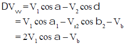
The useful tangential force = (mass flow × tangential component of inlet jet velocity) - (mass flow × tangential component of exit jet velocity).
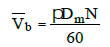
The mean peripheral (blade) speed of the rotor is related to the mean diameter and speed of rotation by the standard relation:
Vb = π Dm N / 60 where Dm is mean wheel diameter and N the rotational speed in rpm.
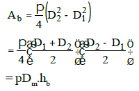
Flow area and blade annulus
The steam flow through the rotor forms an annular passage. For practical design the annular flow area may be approximated using the mean diameter and blade height:
A ≈ π Dm hb where hb is the blade (or annulus) height.
Velocity triangles and diagram work
Velocity triangles at the blade inlet and exit are essential for analysing impulse turbines. The standard notation used in velocity diagrams is:
- V1 - absolute velocity of steam at blade inlet
- V2 - absolute velocity of steam at blade exit
- Vr1, Vr2 - relative velocities at inlet and exit
- Vb - blade peripheral (tangential) velocity
- α - nozzle angle (jet direction)
- β1, β2 - blade inlet and outlet angles (measured relative to blade motion)
The diagram (or blading) work per unit mass of steam is the tangential thrust times blade speed; it is commonly derived from the velocity triangles and the momentum equation.
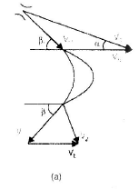
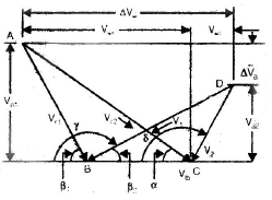
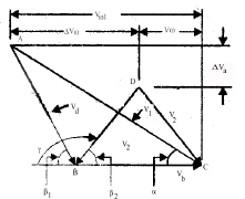
Diagram (blading) work and axial thrust
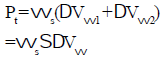
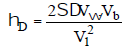
From the velocity triangles the tangential thrust Pt and therefore the diagram work WD can be obtained. If ws is mass flow rate of steam then:
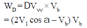
- Diagram work WD = Pt × Vb
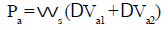
- Axial thrust arises from axial components of jet velocities and equals Pa = D Va × ws (D denotes appropriate dimension in the expression as per momentum components).
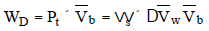
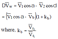
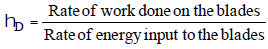
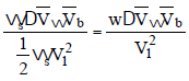
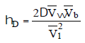
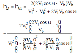
Diagram efficiency (blading efficiency)
Diagram efficiency (also called blading efficiency) is the ratio of energy converted by the blades to the kinetic energy available in the jet issuing from the nozzle.
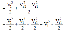
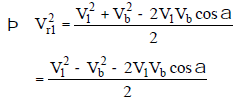
Energy input to the blade per unit mass equals the kinetic energy associated with the jet at nozzle exit minus kinetic energy of steam leaving the blade.

Therefore the diagram efficiency is defined as the useful work obtained from the blades divided by the kinetic energy supplied by the nozzle.
Optimum velocity ratio for simple impulse stage
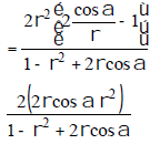
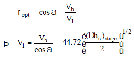
The velocity ratio r is defined as the ratio of blade peripheral speed to nozzle jet speed:
r = Vb / V1
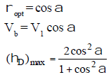
Using velocity triangle relations and maximising diagram efficiency with respect to r yields the optimum relation (for symmetrical, frictionless blading):
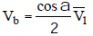
Vb,opt = (V1 cos α) / 2 so ropt = 0.5 cos α.
At this velocity ratio the blading extracts the maximum possible work from the nozzle jet, neglecting blade friction and incidence losses.


Note: A lower nozzle angle α (i.e. a jet more aligned with the tangential direction) tends to increase blading efficiency, but too small an angle may cause incidence losses at blade inlet.

Compounding of Steam Turbines
When steam expands from boiler to condenser in a single stage, nozzle jet velocities become very large, producing extremely high rotor speeds (as in the single-stage de Laval turbine). High speeds cause large centrifugal stresses, excessive frictional losses and impractical rotor designs. To reduce peripheral speeds and make the turbine practical, the total expansion is divided into a number of stages - this process is called compounding or staging.
- One nozzle row followed by one moving blade row is called a stage.
- Two principal methods of compounding:
- Pressure compounding (Rateau staging)
- Velocity compounding (Curtis staging)
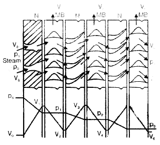
Pressure compounding (Rateau staging)
In pressure compounding the total enthalpy (and pressure) drop is divided across several stages by using multiple sets of nozzles. Each stage has its own nozzle which produces a jet; each jet is matched to a corresponding moving blade row. The pressure and enthalpy drop occur only in the fixed nozzles, not in the moving blades.
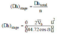
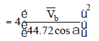
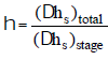
For example, in a 4-stage Rateau turbine the total enthalpy drop between boiler and condenser is split equally among four nozzle rows; consequently the jet velocity from each stage is smaller than the single-stage jet. If h0 - h4 is total isentropic enthalpy drop, the jet velocity for a single stage is proportional to √(h0 - h4), while for an n-stage turbine the per-stage velocity is reduced roughly by √n factor if enthalpy is equally divided.
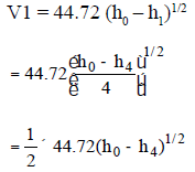
In general, splitting an enthalpy drop across n stages reduces the jet velocity per stage and therefore allows practical rotor speeds.
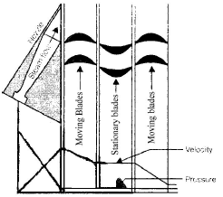
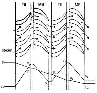
Velocity compounding (Curtis staging)
Velocity compounding (or Curtis staging) concentrates the pressure/enthalpy drop in a single set of nozzles, producing a high-velocity jet. The large kinetic energy of this jet is then absorbed in several successive moving blade rows separated by stationary guide blades. Each moving row reduces the absolute velocity and extracts part of the kinetic energy; guide blades redirect the flow to the next moving row.
This arrangement allows a large enthalpy drop to be handled without single-stage high peripheral speed, by partitioning the kinetic energy absorption across several rotor rows.
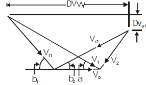
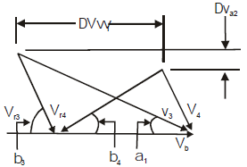
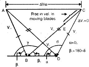
Notation commonly used in two-row Curtis stage:
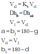
- Kb - blade friction factor
- a1 - exit angle of guide blades
- b1, b2 ... - inlet and exit angles of successive moving blade rows
- ΔVa1, ΔVa2 - change in axial components for successive rows
- ΔVw1, ΔVw2 - change in whirl (tangential) components for successive rows
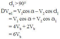
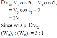
The diagram work, axial and tangential thrusts and the diagram efficiency are obtained by applying momentum to each moving row and summing contributions across the rows.
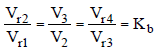
Effectiveness and blade friction
The distribution of work between successive moving rows depends on blade friction factor Kb and blade geometry. If Kb = 1 (an idealised assumption), an example result for a two-row stage is that about three-quarters of total work is obtained from the first moving row and one-quarter from the second. For a 3-row Curtis stage the relative contributions approximate 5 : 3 : 1 for rows 1, 2 and 3 respectively (idealised case).
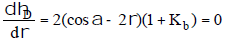
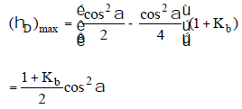
Optimum velocity ratio for Curtis stage
For a symmetrical two-row Curtis stage with discharge not axial, the expression for available diagram enthalpy and hence the optimum velocity ratio can be derived from the combined velocity triangles of the rows. In the frictionless, symmetrical case closed-form expressions give the maximum diagram efficiency; with friction included the optimum shifts and efficiencies are reduced.

Reaction Turbines
In a reaction turbine the pressure drop (and associated enthalpy drop) occurs partly in the fixed blades (stator) and partly in the moving blades (rotor), because the moving blade passages are themselves of convergent/divergent nozzle shape. The flow expands within the rotor passages and this produces reaction forces which contribute to rotor torque. Thus reaction turbines derive motive force from both impulse and reaction effects; they are often described as impulse-reaction turbines.
Degree of reaction
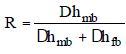
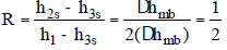
The degree of reaction R measures the fraction of the stage enthalpy drop that occurs in the rotor (moving blades):
R = (enthalpy drop in moving blade) / (total stage enthalpy drop)
Special cases:
- R = 1 - pure reaction (historically Hero's turbine is cited as an example)
- R = 1/2 - 50% reaction (common practical design; Parsons turbine is a well-known 50% reaction design)
Velocity diagrams and blading
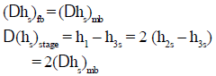
For a 50% reaction stage (R = 0.5) the fixed and moving blades are typically similar in shape; the isentropic enthalpy drop of the stage is equally split between the fixed and moving blades. The velocity diagram for a 50% reaction stage shows symmetry between stator and rotor velocity triangles, and the diagram work is obtained from the change in whirl component across the rotor.
Energy input and diagram efficiency
The energy input to the blade per kg of steam, diagram work and diagram efficiency for reaction stages are obtained from the velocity diagrams taking account of enthalpy changes in both stator and rotor.
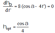
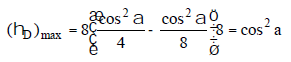
Maximising blading work: differentiating the expression for diagram work with respect to r and setting to zero gives the optimum r for maximum blading work and hence maximum diagram efficiency in the idealised case.
For a simple ideal reaction stage the specific blading work at maximum blading efficiency simplifies to WD = Vb2 under the usual symmetrical assumptions.
Because both fixed and moving blades act as nozzles in reaction stages, careful aerodynamic design of blade profiles and passages is necessary to reduce losses.
Carry-over Efficiency and Combined Efficiencies
Carry-over efficiency hco accounts for the fact that kinetic energy associated with steam leaving one stage is not completely available to the next stage; some loss occurs in the interstage passages. The kinetic energy leaving one stage available to the next may be written as hco × (V2/2).
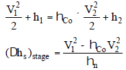
When both nozzle losses and carry-over losses are considered, a combined efficiency term (combined nozzle and carry-over efficiency) is used in stage calculations.
Note: In the ideal frictionless case optimum efficiencies for simple impulse, Curtis and reaction blading may be comparable. When realistic friction and incidence losses are included, reaction blading often shows higher overall efficiency because of lower nozzle exit velocities and reduced profile losses per stage.
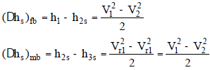
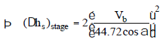
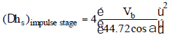
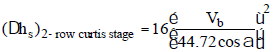
Comparison of Stage Types and Enthalpy Drops
For equal mean blade speed Vb, the enthalpy drops and equivalent number of stages differ among stage types:
- Simple impulse stage
- 2-row Curtis (velocity) stage
- 50% reaction stage
For example, a 2-row Curtis stage may be equivalent to several simple impulse stages in terms of enthalpy absorption. Specific relations for enthalpy drops per stage for each type follow from the stage velocity and geometry and are illustrated in standard turbine design texts.


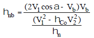
Nozzle and Blade Heights
Nozzle and blade heights are determined from the required mass flow rate and the annular area available for flow at the nozzle exit and blade entrance.
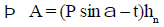
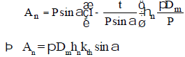
If O is the circumferential width of the flow passage at exit and hn is nozzle height, the exit area for one nozzle is approximated as O × hn. The pitch P, wall thickness t and admission arrangement determine O (P sin α = O + t as an approximate geometric relation for full peripheral admission).
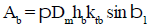
Assuming full peripheral admission and an appropriate thickness factor kth for nozzle walls, the total nozzle area is obtained by summing over all nozzles. Similarly an edge thickness factor ktb is used for blade entrance area. For practical machines kth ≈ ktb. Design practice usually makes blade entrance height slightly greater than nozzle exit height (an allowance called overlap) to avoid spilling of the jet from the nozzle into the rotor passages.


Blade and nozzle heights must satisfy aerodynamic, mechanical and manufacturing constraints while giving the required flow area for the design steam mass flow.
Turbine Governing and Control
Governing of a steam turbine means regulation of the steam supply so as to maintain constant rotor speed under varying load conditions. Common methods of turbine governing include:
- Throttle governing - regulating the steam pressure/flow by throttling upstream of the turbine
- Nozzle governing - controlling the number of nozzles or the effective nozzle area admitted to steam (partial admission or on/off nozzle groups)
- By-pass governing - diverting steam around parts of the turbine (used in some control arrangements)
Reheat Factor and Condition Line
Because real expansion through stages is irreversible and there are interstage mixing and frictional effects the actual energy available stage-by-stage differs from the ideal isentropic division. The portion of available energy not converted to work in a stage and remaining in the fluid is referred to as reheat. Key points:
- Reheat increases entropy; it represents available energy not used in the stage.
- Reheat produced in a stage (except the last) may partly be available to the following stages; the last stage's reheat is a loss.
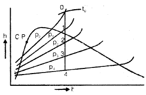
- Constant pressure lines diverge on the T-s or h-s diagram with increasing entropy; as a consequence the sum of per-stage isentropic enthalpy drops may exceed the single-step isentropic enthalpy drop for the whole turbine.
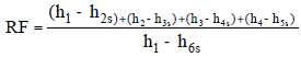
- The locus of actual states of steam at exit of each stage is called the condition line. The ratio expressing the effect of stagewise reheat relative to equal ideal enthalpy division is called the reheat factor (RF).
Losses in Steam Turbines
Real turbines suffer a number of losses. Major loss categories are:
- Regulating valve losses - throttling and local irreversible pressure losses in main and regulating valves; typically a few percent of inlet pressure may be lost.
- Nozzle friction losses - boundary-layer growth, eddies and wall friction in nozzle passages. These depend on passage length, height and flow regime; turbulent boundary layers give higher losses than laminar ones.
- Blade (profile) losses - losses in moving blades due to impingement, skin friction, turning (incidence and deviation), and wake formation behind blade surfaces.
- Disc friction losses - viscous friction between rotating discs and surrounding steam (momentum exchange produces a drag that consumes part of the power).
- Partial admission and scavenging (windage) losses - when nozzles admit steam only over part of the circumference, blades must clear the steam in the passages causing scavenging losses; combined with disc friction these are often called windage losses.
- Gland and leakage losses - steam leakage through diaphragms and shaft glands between stages and at the shaft ends; diaphragm leaks and shaft seals reduce the useful mass flow or transfer energy to unwanted paths.
- Residual (exhaust) velocity loss - kinetic energy of steam leaving the last stage that cannot be converted to shaft work and is lost in the exhaust.
- Carry-over losses - losses in interstage passages reducing the kinetic energy transferred from one stage to the next (represented by carry-over efficiency hco).
- Wetness and erosion - if steam quality is low (say < 0.88="" water="" fraction="" appreciable)="" droplet="" erosion="" and="" corrosion="" of="" blades="" occur="" and="" reduce="" performance="" and="">
- External mechanical losses - friction in bearings, power consumed by oil pumps, governors and other auxiliaries; surface heat losses are small when insulation is adequate.
Designers aim to reduce these losses by optimising nozzle and blade profiles, improving surface finishes, minimising clearance leaks, providing adequate sealing and stage matching, and choosing an appropriate number and type of stages for the required total enthalpy drop.
Summary
This chapter has described the fundamental principles of steam turbines: impulse and reaction working, velocity triangles, blading (diagram) work and efficiency, compounding (pressure and velocity), degree of reaction, nozzle and blade geometry, governing methods, reheat and condition line concepts, and the principal losses that determine real turbine performance. Familiarity with velocity triangles and momentum analysis is essential for analysing and designing turbine stages and for understanding stage matching in multi-stage machines.
FAQs on Steam Turbines
| 1. How does a steam turbine work? |  |
| 2. What are the different types of steam turbines? | |
| 3. What are the main components of a steam turbine? | |
| 4. What factors affect the performance of a steam turbine? | |
| 5. How is the efficiency of a steam turbine measured? | |


