Mechanical Engineering Exam > Mechanical Engineering Notes > SSC JE (Technical) > Vapour Compression Cycle
Vapour Compression Cycle


If in a Reversed Carnot Cycle
Refrigerant is compressed from dry saturated condition. The expander of the reversed Carnot cycle is replaced by a throttling device. The modified cycle obtained is the vapour compression cycle, which retains the advantages of the reversed Carnot cycle while being practical for engineering use when a vapour refrigerant is employed.
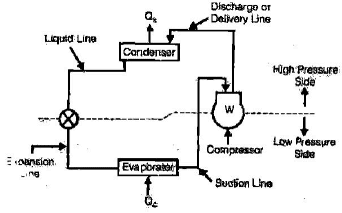
Basic components and processes of the Vapour Compression Cycle
- Compressor - Raises the pressure and temperature of the refrigerant vapour from evaporator pressure to condenser pressure. Compression may be idealised as isentropic in simple analyses but in practice is polytropic due to friction and heat transfer.
- Condenser - Rejects heat from the high-pressure vapour to the surroundings, condensing the refrigerant to a liquid (often with some subcooling).
- Expansion device (throttling valve) - Reduces the pressure of the liquid refrigerant abruptly; the process is approximately isenthalpic (constant enthalpy), producing a two-phase mixture at evaporator pressure.
- Evaporator - Absorbs heat from the space or process to be refrigerated, causing the refrigerant to evaporate at low pressure and low temperature, producing the suction vapour that enters the compressor.
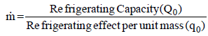
Refrigerant circulation rate
The mass circulation rate of refrigerant required depends on the refrigerating effect per unit mass and the cooling load. Key parameters used in calculations are the specific enthalpies at states of the cycle and the specific volume of suction vapour.
Suction vapour and compressor displacement
- Volume of suction vapour = m × V1, where m is mass flow rate and V1 is the specific volume of vapour at suction conditions.
- Specific volume V1 - specific volume of the vapour at suction (evaporator) pressure and temperature.
- Actual piston displacement volume of compressor - determined from the required suction volume and the volumetric efficiency (hv) of the compressor.
- Volumetric efficiency (hv) - accounts for leakage, re-expansion of clearance gas and other effects that reduce the effective intake volume of a positive displacement compressor.
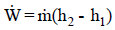
- Power consumption of compressor - equals mass flow × (h2 - h1) for an idealised cycle, where h1 and h2 are inlet and discharge specific enthalpies respectively; real compressors include mechanical losses and non-ideal compression.
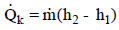
- Heat rejected in the condenser - equals mass flow × (h2 - h3) where h3 is the enthalpy after condensation (liquid state).
- Superheat discharge temperature - discharge vapour may be superheated; the superheat temperature and enthalpy determine the actual compressor discharge conditions.
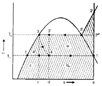
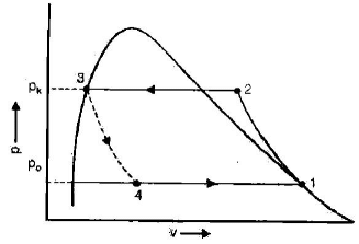
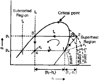
- Refrigerating effect = (h1 - h4) = Q0, where h4 is the enthalpy after the throttling (at evaporator inlet) and h1 the enthalpy of suction vapour. The refrigerating effect per unit mass is the useful cooling produced in the evaporator.
- Effect of suction condition on COP - For some refrigerants (for example R-11, R-22 and ammonia) a wet suction state may give maximum COP; for many other refrigerants, suction from a superheated state gives maximum COP.


Deviations of a practical vapour compression system from the idealised vapour compression cycle
- Superheating of vapour in the evaporator beyond the saturated vapour line.
- Heat gain and additional superheating of vapour in the suction line (between evaporator and compressor).
- Pressure drop in the suction line.
- Polytropic (non-isentropic) compression in the compressor due to friction, heat transfer and mechanical inefficiencies.
- Pressure drop across discharge valves and piping.
- Pressure drop in the condenser and evaporator flow paths.
- Subcooling of liquid in the condenser and heat gain in the liquid line to the expansion device.
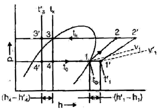
Effect of operating conditions on COP of the vapour compression cycle
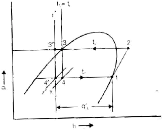
Effect of decrease in evaporator pressure
- Decrease in refrigerating effect (smaller enthalpy change across the evaporator for given mass flow).
- Increase in specific volume of suction vapour (V1 increases), which increases compressor displacement for the same mass flow.
- Decrease in volumetric efficiency of compressor due to increased clearance losses and larger pressure ratio.
- Increase in compressor work because of higher compression ratio to reach the same condenser pressure.
Effect of increase in condenser pressure
- Decrease in refrigerating effect because the condenser pressure rise increases the enthalpy at compressor discharge and hence reduces the net enthalpy drop across the evaporator for a fixed evaporator pressure.
- Increase in compressor work because compression must be to a higher discharge pressure.
- Decrease in volumetric efficiency of compressor due to increased final compression pressure and higher operating temperatures.
- Increase in mass flow of refrigerant can occur to meet the same cooling load if refrigerating effect per unit mass falls.
- Net effect on COP: COP decreases with both decreasing evaporator pressure and increasing condenser pressure. The effect of decreasing evaporator pressure is generally more detrimental to COP than an equal change in condenser pressure.
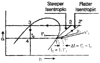
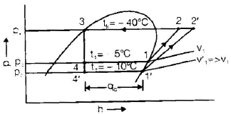
Effect of suction vapour superheat
- Increase in refrigerating effect when superheat raises the enthalpy at suction, if the liquid enthalpy at evaporator inlet remains same.
- Increase in specific volume of suction vapour, increasing compressor displacement and reducing volumetric efficiency.
- Increase in compressor work because compressor must compress a higher enthalpy vapour from a higher suction temperature.
- Superheating ensures complete vapourisation of any residual liquid before entering the compressor, protecting the compressor from liquid slugging.
- For R-12, suction vapour superheat generally increases COP because the relative gain in refrigerating effect outweighs the extra compressor work.
- For R-22 and ammonia systems, suction vapour superheat typically decreases COP because the increase in compressor work is larger than the gain in refrigerating effect.
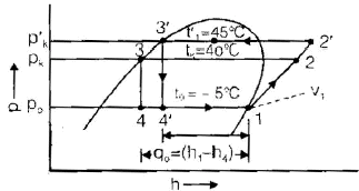
Effect of liquid subcooling
- Subcooling the liquid refrigerant at condenser outlet reduces the vapour fraction after throttling and increases the enthalpy difference (h1 - h4) across the evaporator for the same mass flow, thereby increasing refrigerating effect.
- Compressor work is approximately the same for the same pressures and suction conditions, therefore COP increases with liquid subcooling.
If energy gained by subcooling is utilised in superheating the suction vapour
- For R-12, using the subcooling energy to superheat suction vapour leads to decreased work per TR (ton of refrigeration) and an increase in COP.
- For R-22 and ammonia, this reallocation often increases work per TR and decreases COP.
- In practical design there is usually a larger pressure drop in the evaporator than in the condenser; therefore, pressure drop in the evaporator is particularly critical and must be minimised where possible.
Key formulae and design relations (summary)
- Refrigerating effect per unit mass = h1 - h4 = Q0.
- Compressor work per unit mass (idealised) = h2 - h1.
- Heat rejected in condenser per unit mass = h2 - h3.
- COP (Coefficient of Performance) = Refrigerating effect per unit mass / Compressor work per unit mass = (h1 - h4)/(h2 - h1).
- Mass circulation rate = Cooling load / (h1 - h4).
- Piston displacement required = m × V1 / (hv × ρ) - computed using specific volume at suction and compressor volumetric efficiency; exact forms depend on compressor geometry and units used. (Refer to the specific displacement relation shown in the system design images.)
Practical considerations and design notes
- Maintain sufficient suction superheat only to avoid liquid carry-over; excessive superheat reduces COP for some refrigerants.
- Provide controlled subcooling in the condenser to improve refrigerating effect and COP.
- Minimise pressure drops in evaporator and suction lines to preserve evaporator pressure and volumetric efficiency.
- Account for non-ideal compression, mechanical losses, and heat gains/losses in piping when estimating actual COP and power consumption.
- Select refrigerant and heat-exchanger designs considering safety, capacity, thermodynamic properties and system COP under expected operating conditions.
The document Vapour Compression Cycle is a part of the Mechanical Engineering Course Mechanical Engineering SSC JE (Technical).
All you need of Mechanical Engineering at this link: Mechanical Engineering
FAQs on Vapour Compression Cycle
| 1. What is a vapour compression cycle in mechanical engineering? |  |
Ans. A vapour compression cycle is a thermodynamic process used in mechanical engineering to transfer heat from a lower temperature source to a higher temperature sink by using a refrigerant. It is commonly used in refrigeration and air conditioning systems to cool or heat spaces or substances.
| 2. How does a vapour compression cycle work? | |
Ans. In a vapour compression cycle, the refrigerant undergoes a series of processes. First, it is compressed in a compressor, increasing its pressure and temperature. Then, it passes through a condenser where it releases heat to the surroundings and changes from a gas to a liquid. The liquid refrigerant then flows through an expansion valve, reducing its pressure and temperature. Finally, it enters the evaporator where it absorbs heat from the surroundings and evaporates back into a gas. This cycle repeats to maintain the desired cooling or heating effect.
| 3. What are the components of a vapour compression cycle? | |
Ans. A vapour compression cycle consists of several key components. These include a compressor, condenser, expansion valve, and evaporator. The compressor is responsible for raising the pressure and temperature of the refrigerant. The condenser allows the refrigerant to release heat and condense into a liquid. The expansion valve lowers the pressure and temperature of the liquid refrigerant before it enters the evaporator. The evaporator absorbs heat from the surroundings, causing the refrigerant to evaporate and complete the cycle.
| 4. What are the advantages of a vapour compression cycle? | |
Ans. The vapour compression cycle offers several advantages in mechanical engineering applications. Firstly, it provides efficient heat transfer, allowing for effective cooling or heating. It also allows for precise temperature control and can be easily adjusted to meet varying demands. Additionally, the cycle is reliable and widely used, with established design guidelines and readily available components. Finally, the use of refrigerants in the cycle makes it environmentally friendly compared to other cooling or heating methods.
| 5. What are the limitations of a vapour compression cycle? | |
Ans. While the vapour compression cycle is widely used, it does have some limitations. One limitation is the need for a constant power supply to operate the compressor. This can be a drawback in remote or off-grid locations. Another limitation is the potential for refrigerant leakage, which can contribute to environmental concerns. Additionally, the cycle may not be suitable for certain extreme temperature conditions or for applications requiring very low temperatures. Proper maintenance and design considerations are necessary to mitigate these limitations.
About this Document

2.5K Views

4.76/5 Rating

Apr 21, 2026 Last updated
Related Exams
Document Description: Vapour Compression Cycle for Mechanical Engineering 2026 is part of Mechanical Engineering SSC JE (Technical) preparation. The notes and questions for Vapour Compression Cycle have been prepared according to the Mechanical Engineering exam syllabus. Information about Vapour Compression Cycle covers topics like and Vapour Compression Cycle Example, for Mechanical Engineering 2026 Exam. Find important definitions, questions, notes, meanings, examples, exercises and tests below for Vapour Compression Cycle.
Introduction of Vapour Compression Cycle in English is available as part of our Mechanical Engineering SSC JE (Technical) for Mechanical Engineering & Vapour Compression Cycle in Hindi for Mechanical Engineering SSC JE (Technical) course. Download more important topics related with notes, lectures and mock test series for Mechanical Engineering Exam by signing up for free. Mechanical Engineering: Vapour Compression Cycle
Description
Vapour Compression Cycle of Mechanical Engineering SSC JE covers all the important topics, helping you prepare for the Mechanical Engineering exam on EduRev.
Information about Vapour Compression Cycle
In this doc you can find the meaning of Vapour Compression Cycle defined & explained in the simplest way possible. Besides explaining types of Vapour Compression Cycle theory, EduRev gives you an ample number of questions to practice Vapour Compression Cycle tests, examples and also practice Mechanical Engineering tests


Related Searches
Previous Year Questions with Solutions, ppt, Vapour Compression Cycle, past year papers, Exam, pdf , Objective type Questions, study material, Free, Vapour Compression Cycle, Important questions, Sample Paper, practice quizzes, shortcuts and tricks, Viva Questions, Summary, MCQs, Vapour Compression Cycle, Extra Questions, video lectures, mock tests for examination, Semester Notes;